

Jeremy Harris
-
Posts
26430 -
Joined
-
Last visited
-
Days Won
360
Everything posted by Jeremy Harris
-

Gap between insulation, DPM querys
Jeremy Harris replied to ninja432's topic in General Self Build & DIY Discussion
The cavity only needs to be enough for ventilation, could be as little as 50mm I think. The joists you're proposing are way too small, I'm afraid. For a 4.2m span with joists at 400mm centres they would need to be at least 220 x 38 (that's very slightly undersize) and should ideally be either 220 x 47 or 235 x 38. Joists that were just 95 x 45 spaced on 600mm centres would only span a maximum of about 1.4m. I suspect that laying insulation directly on the existing slab and then laying a membrane and screed would give you the lowest floor build up thickness. -
As a tip, we had blinds made to fit our front gable glazing. Be prepared for a hefty bill, as there are only a few companies who are able to make blinds to fit a gable and they are far from being cheap (think thousands, not hundreds). The blinds do nothing to keep the solar gain down, unfortunately, we needed to fit external infrared reflecting film to the windows to help reduce that, but the blinds do add privacy. With hindsight, we could have saved money by opting to fit smart glass to this elevation, as even though it would have cost perhaps £1000/m² for the glass, it would have been worth it overall.
-
Extractor not staying on (on lighting circuit)
Jeremy Harris replied to gravelld's topic in Electrics - Kitchen & Bathroom
Well done! The test results do indeed seem to confirm that the top terminal is the switched line (L1) and the bottom terminal is the permanently on line (L), with the right hand terminal being the neutral. If you connect a 3 core + E cable as suggested earlier then the fan should work as intended. The 15V you measured when the switch was off will just be induction, and is normal. These induced voltages in cables are one reason that the volt pen type detectors are pretty useless, as they will often light up from an induced voltage. A meter discriminates between a low induced voltage and the supply voltage, so is usually more reliable. -
Extractor not staying on (on lighting circuit)
Jeremy Harris replied to gravelld's topic in Electrics - Kitchen & Bathroom
CPC = Circuit Protective Conductor, the physical wire that is connected to PE, the Protective Earth (commonly just called earth) EICR = Electrical Installation Condition Report, the report produced following the inspection and test of an electrical installation. -
You'll still find that the MVHR won't work at all well when the stove's running, as it will be massively imbalanced, with most of the extract air going through the stove, and bypassing the heat exchanger. No amount of playing with fan setting can fix that, it's an inherent consequence of drawing loads of room air out through the flue. Have you considered a local external air feed for the stove? That would make a significant difference.
-
Extractor not staying on (on lighting circuit)
Jeremy Harris replied to gravelld's topic in Electrics - Kitchen & Bathroom
First off, I'd not be that confident about trusting the results from a voltage detector pen/screwdriver thing, as they are notoriously unreliable. Perhaps gain some confidence from trying out the test meter on an easy to access circuit, making sure that the meter is set to measure AC voltage and the test leads are plugged into the voltage sockets on the meter (if there is a choice). If you keep your hands clear of any live terminals the worst that can happen is that you will blow a fuse in the meter if you get something wrong. With luck you should gain a bit of confidence and feel OK with carefully testing the terminals in the junction box. I've been trying to label the various cables into that junction box with where I think they go/come from: Some connections are certain. The earth on the left, the neutral on the right and the switched line at the top (this has to be right as it goes to a light drop). The area of uncertainty is the lower terminal, as it's not clear that the switch cable has a line (red) connection to it, as it's hidden under what I think is the incoming power cable. If you don't want to use the test meter, then I would suggest that you remove the cable running to the fan, with its dodgy earth conductor being used as a switched line, and run a length of 3 core + E so that the earth connects to the earth terminal (with green/yellow sleeving), the brown wire goes to the line terminal at the bottom, the black wire (sleeved with brown) goes to the switched line terminal at the top and the grey wire (with a blue sleeve) goes to the neutral terminal at the right. I know this colour coding seems at odds with what you've got, but under the harmonised rules black can be a phase colour like brown, so shouldn't be used for neutral.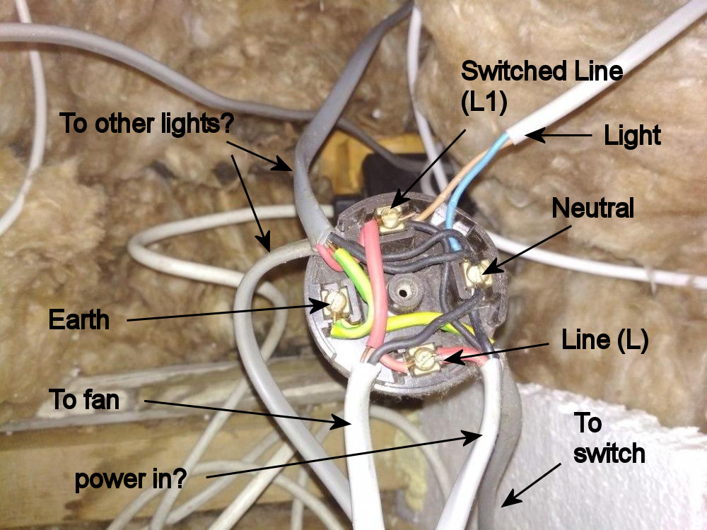
-
Is the multifuel stove room-sealed? i.e. does it have a sealed external air supply duct coming in from outside? If not, then I'd forget about MVHR, as the imbalance created when the stove is running will massively overwhelm the fans in the MVHR, almost certainly leading to no useful benefit. In effect, the combustion air being drawn into the stove will bypass the MVHR heat exchanger and reduce the pressure in the house, leading to poor heat recovery, as most of the extract air will probably be flowing through the stove, rather than the MVHR heat exchanger. Might help with decision making, knowing this up-front, perhaps!
-
Extractor not staying on (on lighting circuit)
Jeremy Harris replied to gravelld's topic in Electrics - Kitchen & Bathroom
Going from the bottom photo up, the light switch shows clearly that the lighting is wired as loop in fitting ( https://www.practicaldiy.com/electrics/lighting-wiring/light-wiring-loop.php ). The two conductors in the switch cable are the line (red) and switched line (black with red sleeve). This means decoding the cables going into the junction boxes, which gets a bit less certain to work out by remote control. Dealing with the top photo, with the cable to the fan. First a few observations and questions. Is the flex with the new harmonised colours the drop down to a light fitting? It really needs tidying up so that there are no single insulated conductors exposed, with the outer sheath inside the junction box (or better still made off to a separate junction that includes a cable clamp). I'm guessing here, as it looks like the switched live red sleeve has been left off from the switch cable, and I'm assuming that the switch cable is the one that is coming in at the lower right, with the black conductor (which should be red sleeved) being the switched line, leading to the terminal at the top. Referring just to the top photo, I think that the terminals in that junction box are: Top - Switched line to light (and should go to the fan L1 terminal) Left - Earth Right - Neutral to light (and should go to the fan N terminal) Bottom - Permanently on line to switch (and should go to the fan L terminal) It's good practice to run the feed to the fan (the L, L1 and N) through a 3 pole isolator switch, so the fan can be isolated without needing to isolate the lighting circuit. If you have a meter, then it would be a good idea to test the terminals in the junction box in the top photo to be sure that the connections are as I think they may be. Testing between the bottom terminal and the right hand terminal should show as being live when the power is on. Testing between the right hand terminal and the top terminal should only be live when the light switch is on (with the power on). -
Gap between insulation, DPM querys
Jeremy Harris replied to ninja432's topic in General Self Build & DIY Discussion
No, that's breather membrane, and is vapour permeable. It's intended to go on the outside, in order to allow water vapour to escape through it. It's not a matter of opinion, it's a fact that a vapour tight membrane goes on the inside and a vapour permeable breather membrane goes on the outside. -
Gap between insulation, DPM querys
Jeremy Harris replied to ninja432's topic in General Self Build & DIY Discussion
I'm sure that planning permission isn't required, as the floor area is under the limit I suspect, but Building Regulations approval will be required, as a studio will be classified as a habitable room, I'm reasonably sure. In all probability it won't be too much hassle to gain Building Regs approval, but you will need to make an application and either go for full plans approval before you start work, or opt to do the work via a building notice. The latter would be probably the best route for a modest conversion project like this. There are details of what's needed here: https://www.gov.uk/building-regulations-approval -
Gap between insulation, DPM querys
Jeremy Harris replied to ninja432's topic in General Self Build & DIY Discussion
Conversion of a garage to a habitable room definitely needs Building Regs approval. -
Gap between insulation, DPM querys
Jeremy Harris replied to ninja432's topic in General Self Build & DIY Discussion
The vapour membrane is the vapour tight layer on the inside face of the insulation, that's there to prevent moisture in the warm air inside the house from moving out through the structure and condensing in the colder outer layers. It's really just a plastic sheet that's fixed and taped to the inside surface, or maybe a vapour tight board, or even foil-faced insulation with the joints taped up. The floor joists could be supported on blocks, or on hangars from the walls. Alternately you could just lay insulation down directly on the existing concrete floor, add a membrane over it then use a screed for the new floor. A screed is just a layer of concrete or other material that can be poured, levelled and then hardens to form a flat floor. It can be reinforced to allow a thinner layer to be used if need be. Insulation can be supported in several different ways when fitted between joists. A permeable membrane or netting can be stretched underneath, or slim battens can be fastened as supports. -
Gap between insulation, DPM querys
Jeremy Harris replied to ninja432's topic in General Self Build & DIY Discussion
Is the block wall single skin or a cavity wall? If it's single skin, then it might be a good idea to include a cavity between the timber inner frame and the outer wall. If it's a cavity wall then there's no need for an additional ventilated cavity. With the floor, then I'd be inclined to support the joists above the floor, with a ventilated cavity beneath. No need for a DPM on the concrete side, just a vapour membrane on the warm side. Alternatively, you could opt to lay insulation and a membrane on to the concrete floor, then screed over the top for the finished floor. -
Gap between insulation, DPM querys
Jeremy Harris replied to ninja432's topic in General Self Build & DIY Discussion
So, if I've understood correctly, you're trying to use DPM as a vapour barrier, but want to put it the wrong side of the insulation layer, is that right? Doesn't sound sensible to me, TBH, as it's critical that any vapour tight layer be on the warm side of the insulation layer. Failure to do this may result in interstitial condensation on the outer face of the timbers, where they are fixed to the cold wall, which will cause them to rot. The normal build up for something like this would be to fix the battens to the wall, fit the insulation, then fit a vapour tight layer inside that, and behind the final wall finish on the inside. -
Hi - anyone know about planning regs re gardens and parking?
Jeremy Harris replied to Bev Bruce's topic in Introduce Yourself
Welcome. There will usually be a planning policy that stipulates the parking arrangements that are required. In our case it stipulated that we needed two off-road parking spaces (of set dimensions) with both designed such that cars could always enter and leave through the entrance in forward gear. This meant including a hammerhead turning space in the drive, so cars could always turn around. One of the parking spaces was in the garage (officially) which made things easier, but it was still tricky to get enough space to meet all the requirements (although we also had the added problem of a gradient that exceeded the maximum allowable for a drive). Worth having a look at your local authority planning policies, which should be online somewhere, and seeing what they say. I found that the easiest way to find the relevant policy was to look at recent planning applications for our area and see what had been written in to the decision notices. Trying to find the specific policy that applied without doing this was like looking for a needle in a haystack. -
Gap between insulation, DPM querys
Jeremy Harris replied to ninja432's topic in General Self Build & DIY Discussion
The normal overlap for a DPM joint is at least 150mm, with DPM sealing tape used at the joint. Bolting down through the membrane is fine, all timber frames end up being bolted down through the DPM. -
That's my thoughts. too. Not sure how planning conditions can be discharged individually for each plot, as I'd have thought that the planners would only want to discharge conditions as applied to the whole development.
-
Planning consent conditions can always be challenged, though, especially if they are not supported by any written planning policy. Planners are only allowed to apply conditions that are supported by a written policy, and are required to state the policy that they've applied. Often it seems that they try it on and impose conditions that aren't actually written into any policy at all. It would seem very improbable that there would be any planning policy that stipulated the number and type of external finishes.
-
Which ASHP are set up to cool
Jeremy Harris replied to Triassic's topic in Air Source Heat Pumps (ASHP)
In practice, I've found that there's no problem with running a flow temperature of around 10° to 12°C directly into the UFH for cooling. The floor surface temperature is the critical thing, and this never seems to get below 17° to 18°C, and so never attracts condensation. With an air temperature of 22°C and a floor temperature of 17°C the humidity would need to be about 73% to start to cause condensation on the floor, and we never see more than about 55% inside the house, and then only in cool, damp, weather. With a room temperature of 22° the floor surface could be safely cooled to about 14°C, as that would need an RH of about 61% in order to create condensation. If the room was warmer, say 24°C, then for a maximum RH of 60% the floor surface could be cooled to about 16°C, more than enough to provide very effective cooling in most cases. For a belt and braces approach, it might be an idea to measure the RH and use that to set the minimum flow temperature. This would allow the floor surface to be cooled to, say, 13°C for a room temperature of 24°C and RH of 50%. -
As a Parish Councillor I've dug into this a bit. Our village has had 16 new builds that have attracted CIL, at an average rate of around £20k per house. The Parish has been given £3.5k from CIL. Says it all, really.
-
Heating the house scenario.
Jeremy Harris replied to Russell griffiths's topic in General Self Build & DIY Discussion
The floor won't have cooled, though. That's the big advantage of having a well-insulated slab, it will sit at close to the room temperature and take ages to cool down, and then will only cool down when the house is colder then the slab for a long period of time. @Ed Davies's description above is exactly what happens, and in our case this contrasts sharply with our old house, where the slab was only slightly above ground temperature all year around, as it had no insulation underneath it. At the old house, during the evening after a warm day, the slab wouldn't heat the house, as it was too cold to do so (might be at around 10°C or so). In the new house the slab will be around the same temperature as the rooms during the day, so when you need a bit of heat in the evening the slab provides it, without needing to be topped up by the UFH. In practice the slab sits at around the mean house temperature, so will warm up a bit during hot days, then give back heat to the house and cool down very slightly on cooler days. -
TBH, the solar thermal would have been a very expensive way to heat water, far, far better to go for PV, as at least you can use all the energy generated even when your hot water has been heated up. PV is far better value than solar thermal, in terms of the amount of usable energy you get for your investment, and it's easy enough to add PV later.
-
Our deliveries almost always involved the trucks backing in to the site and then driving out forwards.
-
Heating the house scenario.
Jeremy Harris replied to Russell griffiths's topic in General Self Build & DIY Discussion
You'll find that the new house, with much better insulation and airtightness, just won't lose heat. Take ours as an example. Yesterday it reached about 23°C outside, and the house sat at about 22°C. We had the French doors open to the garden for half the day. Come the evening it cooled down outside, but we just shut the doors and the house was still at about 22°C. We had no heating or cooling on last night, and this morning I came down and the house was at 21.9°C and outside it was 12°C. -
Extractor not staying on (on lighting circuit)
Jeremy Harris replied to gravelld's topic in Electrics - Kitchen & Bathroom
There's no requirement in the regs to fit 3 pole isolators to bathroom fans for TN-C-S or TN-S installations, it's only a requirement for TT installations, and even then it's questionable, IMHO. There is a requirement (462.2 and 464) to fit isolating switches, and there seems to be an assumption that the fuse or MCB in the board is not OK as the only means of isolation for a bathroom/WC fan. As some 3 pole fan isolators are designed to be able to be locked off, I suspect that the requirement in 464 may be driving the apparent need for these things. All the marked fan isolator switches available seem to be 3 pole, presumably to deal with TT installations where this is a requirement, but a 2 pole switch (switching the L and L1 conductors) would technically be OK in any installation that's either TN-C-S or TN-S.

