Jump to content
  • entries
    28
  • comments
    170
  • views
    9849

Pull Test - Ground Screws


mike2016

2011 views

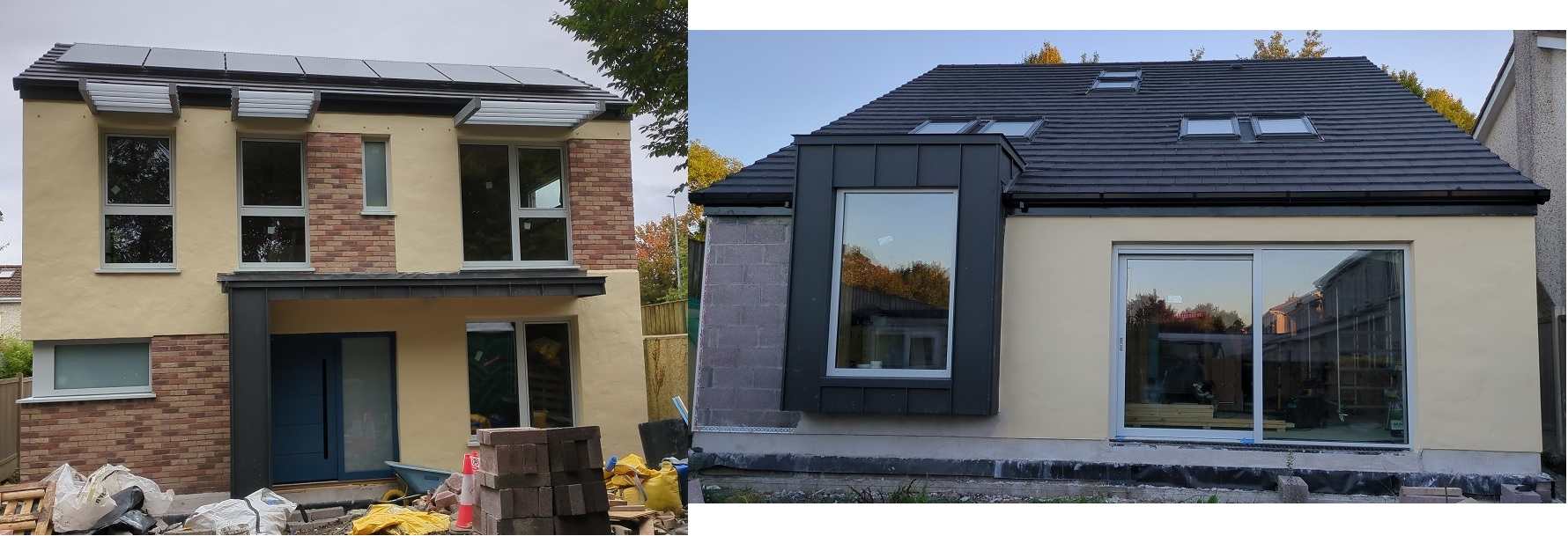
So - Attempt #1 of trying to build my house failed - Made Ground (Poor soil bearing), a buyer who wouldn't grant me legal permission to access the mains water after I sold and changed their mind after I'd let go all the builders, and my planning permission extension was refused. 


Attempt #2:

  • Re-Applied for Planning permission from scratch - preliminary decision due July, final decision August 2023.
  • Place my house back on the market in the meantime somewhere between those two dates. 
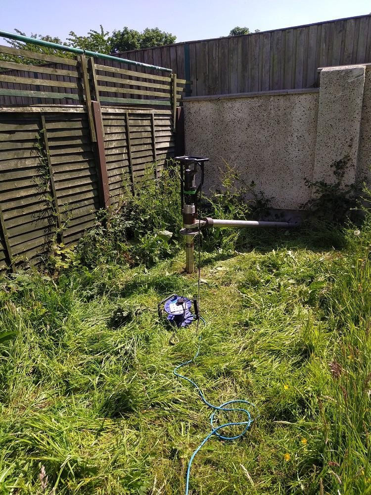
  • Finally I need to find a solution for the poor soil / made ground. Today was that day!


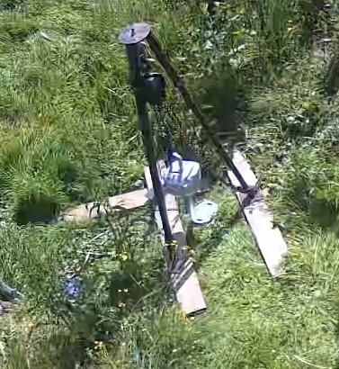
The Structural Engineer got the Ground Screw company to come onsite and put a 1.5 meter screw into the ground in 5 different places and do a pull test against each one. They each held over 4 tonnes of pull pressure which is good and the results will inform the Raft Design so I can get it priced. It was all done with hand tools with a motor assisting the Screw insertion / extraction running on 240v via an Extension lead. Then they put a tripod above the screw and a measurement device to determine the force trying to pull it out. 


Probably looking at 30 or so Ground Screws and a number of Screw Piles for point loads & using a laser level. Had a good chat with the team and they have 5 years of experience and have been to Holland where they source their system from. Due to the coastal conditions there they typically use 6 meter screws! Some soil conditions eat away at screws over time 30-40 microns per year which gives you 50 years guarantee on a 3mm thick screw to allow up to 1500 microns to be eroded. They had heard about some cheaper Chinese screws that were pulled after 3-4 months for a different reason and they had started to rust as their galvanisation was not thick enough. Very bad if that happens! The team do a lot of extensions, shipping containers and garden rooms but houses too. If the screw is exposed more than 500mm you need bracing - this can happen if the ground is sloped. 


The system should save on soil muck away and concrete costs hopefully. Cost wise I'm looking at @ 5K for the ground screws vs digging 2.2 meter strip foundations and muck away costs / concrete as the alternative.


You can sit a foundation on top of the screws and this may mean you don't need a Radon barrier as there is airflow underneath? I'll go with whatever the Structural Engineer recommends though. 


Anyway, thought I'd have a big JCB onsite but this took about 4 hours with powered hand tools and gave me confidence in the system and the team behind it which helps. 


Educational Day all in all!! 

pull test.jpg

pull.jpg

  • Like 4

24 Comments


Recommended Comments

Hi Mike,


That was a very interesting post. Is their an intuitive way to think about how the pull force measurement relates to a downwards load requirement? Or am I missing something? 


Alan

Link to comment

That is a great result. Now you only have to imagine all that muck away, followed by tonnes of concrete. I bet that result made you smile.

  • Like 1
Link to comment
19 hours ago, Alan Ambrose said:

Hi Mike,


That was a very interesting post. Is their an intuitive way to think about how the pull force measurement relates to a downwards load requirement? Or am I missing something? 


Alan

They did try to explain the load factor to me but it didn't quite penetrate my cerebrum! I may still need screw piles for some point loads. There is a lot of contingency built into the calculations for worse soil conditions than mine, higher loadings etc. It's a whole new area to me!

Link to comment

That was a really interesting post thanks very much indeed for writing it.

My only wish is that you had made this post about eight years earlier than today full stop because I would have had another strategy for my 'made ground ' build

  • Like 1
Link to comment
On 06/06/2023 at 19:27, Alan Ambrose said:

post. Is their an intuitive way to think about how the pull force measurement relates to a downwards load

I feel there would have to be certainty that the ground was reasonably uniform. A screw could go through solid clay which would provide pullout resistance but be sitting on soft fill, or even rubbish.

I assume that large numbers of screws allow some contingency.

I've been interested but wary for decades. A Dutch system by experts provides considerable comfort.

Link to comment

sit a foundation on top of the screws and this may mean you don't need a Radon barrier as there is airflow underneath? 


My first thoughts are a perimeter trench including the piles, concreted as a ring beam. Then beam and block floor.

radon barrier isn't much more expensive than a good dpm so isn't the greatest concern. I did many methane barriers using the raised slab principle or gas vents, but always used a methane resistant membrane. It will help it sail through building regs.

Link to comment
On 06/06/2023 at 18:27, Alan Ambrose said:

Is their an intuitive way to think about how the pull force measurement relates to a downwards load requirement

Forces and Motion.

All things being equal, which they are not, the force to push something will be the same as to pull something.

Because of gravity, the force to pull a screw pile upward will be greater than the force to push it downwards.  This difference can be subtracted from the pushing load.

As @saveasteading said, there may be a situation where the end of the screw goes into a void or softer soil.  This would show up as a reduction in power to drive the screw into the ground, the reverse is that the screw hits rock/solid obstruction, the power goes up.

So if you know how much work (J) is done , in how much time (s), how far the screw as been driven (m) you can calculate the force (F) in a simple case. Power = Force x Distance.

I all boils down to the units of kg, m and s.


Wikipedia has this to say on it.


image.png.7164e80d64bd8a4bb910e01c453d3658.png


Link to comment

>>> the force to pull a screw pile upward will be greater than the force to push it downwards.


I appreciate your thinking - e.g. for say a steel bar the 'modulus of elasticity' means that's true over the initial linear region etc.


But ... the pile has unlimited ground underneath for the pressure to be spread over, but limited ground above. Sometimes you see a theoretical diagram of how the pressure is distributed underneath a pile. I can't imagine it's that similar to the pressure distribution above - unless the pile is very deep maybe?

Link to comment

The same applies with augers to remove earth before filling with concrete or gravel. The resistance is shown in the cab, telling the operator when to stop....all precalculated to suit the pile design and the ground.


Some augers are pulled out to leave a cylindrical hole, sending filth everywhere  including the lovely clean stone the pilers required.

Others cut a screw shape out of the ground  to be replaced by concrete. The fins provide additional resistance.When demolished  a concrete auger emerges.

Link to comment

Looking at 80-90 ground screws for my design, a few more than I expected! They need a minimum distance from each other or they don't work as well. The minimum spacing is 10 x the screw shaft diameter (76mm in my case) so min 760mm spacing. Expecting spacing to be 0.75m and 1.75m centers. Build up (top to bottom): 450mm Insulated Raft Foundation, 300mm type 2, groundscrews. Will be interesting to see the final Design. Estimating it might be up to 15K for the groundscrew element alone though! Still to get official pricing though. Hopefully it's affordable....!

Added: There will be 400mm x 400mm plates on the screw heads. I had thought the concrete raft would sit directly on these but there is 300mm type 2 between them. Maybe I'm reading things wrong - geogrid ground reinforcement was also mentioned in this layer. Lots to get my head around! 

Edited by mike2016
Link to comment

I first assumed that the pir and stone are penetrated by the piles so that the concrete loads them directly.

But then the stone does nothing.

Drawings should make this clear. It's good that they are not withholding this info  because the  operative cost must include all the effects on other materials.

For example if it needs a heavily reinforced raft.450mm is already massive, and £50/m2 for concrete purchase alone....that is bridge construction.

Edited by saveasteading
Link to comment

I've got ideas to half the cost that this is going to be. Don't commit. Interested to hear other comments first.


BTW do you have good access ?

  • Like 1
Link to comment

The site is 11m wide, narrow once the structure is built (9m wide) but 22m deep (10m deep house). The 450mm foundation will probably be 300mm EPS with 150 Concrete with rebar as I'm going after a Kore Raft Passive Foundation, ideally 400mm EPS but that's to be discussed as I'm chasing lower U values if possible/affordable. 

Link to comment
1 hour ago, mike2016 said:

300mm EPS with 150 Concrete with rebar

Sorry  , I had misunderstood that was all 450 concrete.


Link to comment

Hi Mike.


Thanks for posting this, very interesting. Also thanks to all the other folk chipping in, makes great informative reading.


I have loads of question and like @saveasteading am enthusiastic about the idea but also cautious.


A few of my thougths are:


The durability. Yes they have a guarentee but if they do have a 3.0mm thick wall then I assume they are galvanised, if so what kind of steel are they using? One weak spot for me seems to be how they connect the plates to the top of the piles, are they welded and if so how is the protective coating made good after? For me I want to design houses economically that are going to last a lot longer than 50 years for many reasons.


I think there may be a lot more lying behind this that you and your SE knows.. but we don't. Anyway for a bit of fun.. and hope this helps crystalise / inform your thoughts.


The muck away cost, depth of made ground and what is in the ground. If you have reasonable access for say a JCB with an extra dig arm and some space at the front of the site to stockpile for lifting with a lorry with a grab then that is a way you could get the muck off site. But what is in the muck? Have you had the ground tested and the soil classified. The easy way to go about this is to phone up local muck away folk that know the area and transport costs etc. Ask them what they need and go from there.


Sometimes you can have a bit of soil that is contaminated and the rest of the site is ok. If you can get a handle on this, say by testing at different depths and places you can work out how much soil is inert and how much falls into say the non hazardous category. The next stage up classification wise and the muck away cost increases a lot. What muckaway contractors can do if you only have some soil that is not inert is to mix it a bit with the inert stuff so that it can all be classified as inert.. and that brings down the cost... can be a lot... like lots!


Do you know why the test pile was only inerted to 1.5m ? Maybe your made ground is not that deep?


I'm curious how the design works holistically. You have neighbours next door? .. what if they build close to the boundary, plant trees or the boundary walls need repair. Will that cause you grief later on if they destabalise your piles.


I wonder if this is worth looking at? My gut feeling is to go for the simple stupid that local contractors can deal with and avoid big costly errors and all the stress that goes with that.


Around the perimeter dig hit and miss pits say 600 mm wide with a 900mm long base at the level of the good ground. These would be spaced at say 2 - 3.0m apart. Think of this a bit like partial underpinning a building. Doing it this way means you are less likely to cause problems with the boundary walls etc. This gives you a series of pits around the perimeter and the boundary walls etc remain stable. Now maybe dig two more lines of pits running front to rear parallel with the side walls of the site. That gives you a grid pattern of pits and splits your effective structural floor slab span into about 2.4 m.. the benefit of the grid is you can span in two directions which introduces economy. Think of it like a carpark floor slab with columns in both directions. You can finnesse this later to deal with point loads. Also the made ground may vary in thickness, A JCB with extra dig (3.5m) will get you down to 2.2 - 2.4m, the extra dig gives the reach to get into the corners of the site and allows the driver a bit more room to manoevre.


You fill the pits with concrete to create piers in the ground. They are just concrete piers and not reinforced with rebar. If the ground does not contain sulphates or has not been used as say a scrap yard where folk have been tipping out acid for years then the concrete will last...acid is not good for concrete as are suplhate rich soils, we need to classify the ground as non aggressive to concrete. If so then I would first look at using a GEN2 concrete. The GEN2 has a compressive strength of 15 N/mm^2 so a fairly week concrete and reasonably cheep. Get a price for that to gain early confidence. You can work out the volumes for muck away. @saveasteading gives the best advice here.


Ok.. when you look at this idea and the practical side.. how do you do that? Well it's all about sequencing of the works.. keep the machine working, the concrete arriving and the muck getting carted away. What you don't do is did all the pits, then try to get the muck away and the concrete later, by that time for example a lot of the pit sides may have collpased.. and then you site will look like it has been cluster bombed.


Start at the back, dig enough for say a 6 or 8 cube concrete waggon, fill the pits and carry on or have the weekend off.


Now you don't have to be that accurate! The site will get churned up a bit, levels will get lost, try and keep the alignment though. The secret is to leave the concrete in the pits high. The next morning the machine just scrapes off the green concrete.  As an aside the general rule for pile placement... we usually design for the pile being 75mm away from where it should be as shown on the drawing.. we are not talking precision here.. it's ground engineering.


Once you have completed the installation of the piers you are out the ground and on your way. Assuming you have a two storey house my starting point would be to aim for a 180 - 200 mm structural slab and then see if I can get that down to the 180mm thick side, if so is there any benefit. Maybe better to have a 200 thick slab on a self build and not have to thicken the slab edges.. much easier to do on site, less opportunity for construction errors.. can we do it flat all the way.


The made ground. Well assume we have scraped off the green concrete tops of the piers to say 0.0mm  / - 50mm. I would want to guard against the fill (made ground) swelling up and lifting the slab. Say there is a bit of swell potential. Lets put a bit of 50mm clayboard in, that once wet falls to bits and lets the ground swell. On a 9.0m span we need some watering holes to collapse the board later, easily dealt with. Main thing is not to leave the piers high as that cuase punching through the structural slab.


Next stage is to design the slab. Now we need to keep an eye on the rebar area vs the slab thickness as it is a structural slab.. story for another day. In essence a slab that is too thick can eat rebar.. so thickness is not always good.


Now we have a structural slab, reinforced locally to deal with point loads.. but really simple and easy to construct. You now have a simple platform to put the rest of the building on top. Simplicity  = Savings.


Put a structure on top with the perimeter built off the slab, use say marmox blocks to make the thermal breaks round the external walls and standard details. There are loads of folk on BH that know this approach like the back of their hand, have been there and worn the tea shirt.. and know it works, some can even prove it.


It may be worth revisiting your design concept, speak to your SE now you have got a bit of feedback from BH. Your SE should be fine with you and recognise that they have a Client that is going through a learning curve. They may ask for a bit more but as folk are hinting on BH there may be different ways of doing this that will easily offset any extra your SE may ask for.


Hope this helps and have fun with your project, it's something very few folk get to do.


Link to comment

It's been a few years since i was down at BRE in Watford. From memory, they have several houses that are built on screw piles. I think they have screw piles that are all linked together with a metal grid frame. I believe that on top of that they have some sort of Lewis deck. From there it is a straightforward timber framed building. I never got the calculations, but did go as far as talking to a screw pile company, and having a design and calculations for a 13 x 11m house. At the time my thoughts were to build with timber I-beams. The cost was very reasonable. The reason i was looking into the system, was because my ground was medium shrinkability, but i had large trees. Poplars, and Oaks.

I would have taken it further except that i had the concern of perhaps in the future having to sell, a bit of an out there, non standard construction house. The cost was slightly over a third of the cost of piling, and a ringbeam.

The other thing that i liked, was the idea, of no digging, no muck away, and no concrete. It has to be a better way, just not something that is standard, and therefore the lenders all crap themselves, or load repayments accordingly.

If i ever get the chance to build a smaller house to see out my days. I would try to do it that way.

My own opinion is that we should only be building houses with a designed lifespan of 60 to 80 years. By that time, any house is about at the end of it's useful life. If you think about most of our current housing stock, to bring them up to modern standards would require most of them to be ripped apart to the point where there is not much left of them.


Link to comment

I was wondering why you needed so many screws. It looks like you are planning on using the one's that actually look like a big screw. In my post above, i was refering to the helictical one's that look a lot more like a boat propeller. I would like to wish you the very best of luck with your project, which i will be following on here.

Link to comment

Thanks Folks,

Lots to think about. I had an extensive ground investigation report commissioned with window sampling and dynamic probing. That's when I realized it was made ground. From the report: 


The sequence of strata encountered were consistent across the site and generally comprised;
• Topsoil
• Made Ground
• Cohesive Deposits
• Granular Deposits
TOPSOIL: Topsoil was present to a maximum depth 0.20mBGL.
MADE GROUND: Made Ground deposits were encountered and were present to depths of between 0.20m
and 1.00mBGL. These deposits were described generally as brown slightly sandy slightly gravelly Clay and
contained occasional fragments of redbrick.
COHESIVE DEPOSITS: Cohesive deposits were encountered beneath the made ground and were
described typically as brown mottled grey slightly sandy slightly gravelly CLAY with occasional subangular
to subrounded cobbles. The strength of the cohesive deposits typically increased with depth and was firm
to stiff or stiff below 2.20mBGL in the majority of the exploratory holes.
GRANULAR DEPOSITS: Granular deposits were encountered below the cohesive deposits and were
typically described as brown/grey sandy clayey fine to coarse subangular GRAVEL with occasional cobbles.
Based on the SPT N values the deposits are typically medium dense and become dense with depth.


The pull test was using 1.5m groundscrews - yep, just like a big wood screw, stainless steel. My original SE was asking for 2.2m deep strip foundations before I sought alternatives, groundscrews / mini-piles being a potential solution. That felt like too much risk, too close to boundaries and would need perfect weather. The groundworker was sure a raft would be fine without any fuss but he can't sign it off, that has to be the SE. Good idea to tease out options and thanks for the extensive explanation above. I'd have to read it a few times to fully get the gist but worth looking into. 


The flange appears to just screw onto the top of the groundscrew and isn't further welded. 


Lifespan of a house, not something I had though about before this exploration! Expiry dates like cartons of milk - I can see insurance firms getting in on the action and charging more for older houses someday! But 50 years will see me out! 

Screenshot 2023-06-16 153434.jpg

  • Like 1
Link to comment

Good info.

To me this is better than the average site in the se  where we've been  building on tips for decades.


Founds to 2.2m seems conservative, with firm ground at 1m.


This has really got my interest xnd I keep thinking "what would I do". Much as I love innovation I think oois  would stick with traditional here.


The 50 years life often surprises people.

When deciding what load needs to apply, there is a conscious input to make on this  because of the increasing possibility of high wind and snow loads.


The Romans overdesigned.

  • Like 1
Link to comment

Fun stuff!


We are building a 6 x 12 m folly on screws overseas.


(because fun, because trying to avoid concrete, because concrete can't be done easily when below zero in winter, and because trucks couldn't get there when soggy in spring and autumn)


Timber framed and floored though. And unmortgegable.


If intending to have a concrete slab anyway I'd question the screws.


If the ground is really iffy they use concrete-on-foam-on-stone-on-whatever as foundations here. There's a even Swedish/Canadian model where they bury air tubes in the slab...initially so that they can pour it in the winter and use an air blower to keep it heated long enough to cure properly when it's minus many outside...later ti use for UFH.


http://www.legalett.ca/frost-protected-shallow-foundations-icf-floors-air-heated-radiant-systems-passive-house-passivhaus-net-zero-energy-buildings-leed-concrete-slab-on-grade-insulation-homes.html


Or if you're suitably bold and building a bungalow with internal load bearing walls perhaps you make the exterior walls only for keeping the rain out (i.e. non loadbearing) and sit the interior walls on wood on foam on gravel on mud...


Edited by markocosic
Link to comment

Yeah, I don't agree with the 50 year lifetime thing.


We need building methods which are not just 'build once' - that is houses should be designed to be taken apart and re-built. Our barn conversion was built several hundred years ago for agricultural use and therefore not expensively. But because it had an OK oak frame structure, it was a fairly easy job to strip off the boarding, roofing etc and re-clad it using some proper insulation etc.


So, build houses with good 'bones' that can be re-built on easily.

Link to comment
4 minutes ago, Alan Ambrose said:

don't agree with the 50 year lifetime thing.

If there wasn't this requirement  there would be nothing.


The building regulations are basically sound, and should ensure much longer than than 50 years if only they were always properly applied.

Link to comment

So the SE has got costs back for both Ground Screws & Piles - 18K vs 35K so we're going the ground screw route. The exact number TBC (currently estimated around 90). They had been looking at a type 2 compacted layer 300mm above the screws but are now looking at a 200mm structural raft foundation directly on top of the screws. Then the insulated foundation is placed on top of this. Bakck of packet costs now as follows:

  • 30K groundworks and install of Kore insulated foundation
  • 7K for Kore EPS
  • 20K groundscrews
  • circa 10k ? for 200mm raft 

So about 70K for the foundation. Against this the Irish Government has waived development contributions and water / sewerage connection charges until next April 2024 if you finish building before Dec 2025 which is 12k + 9K savings so the foundation should work out around 50-60K when all is repriced and if we start say in January 2024. 

With everyone on holidays it will be September before the SE gets back to me with a delivery date for the final design meaning selling my house will delay things into 2024 I'd say. Was holding off hols myself, so this may trigger a break for me before this all kicks off!! 

  • Like 1
Link to comment
On 20/06/2023 at 13:13, Alan Ambrose said:

don't agree with the 50 year lifetime thing.

When we design structures we base the loadings on a 50 year return of snow and wind.*

So how often will we get 1m of snow  or a hurricane? Will one of these occur within 50 years? What chance of them combining is already catered for in euro codes.

That is where 50 years comes from. 

When asked how long my building will last I answer, indefinitely , if you look after it and do proper maintenance.

Build it properly and look after it and don't worry about it failing in 50 years.

Mass housing? Due to quality issues perhaps 50 years has some substance.


* 50 years is the norm. It can be reduced for a temporary structure to save wasting material,  and increased for a good reason.

Link to comment

Create an account or sign in to comment

You need to be a member in order to leave a comment

Create an account

Sign up for a new account in our community. It's easy!

Register a new account

Sign in

Already have an account? Sign in here.

Sign In Now
×
×
  • Create New...