


Annker
-
Posts
231 -
Joined
-
Last visited
-
Days Won
1
Everything posted by Annker
-
Solid wall Internal Wall Insulation (Warm Batten) design
Annker replied to Annker's topic in Heat Insulation
One issue I dont have is moisture passing through the walls from outside. The brickwork is the house bone dry, you cannot imagine how dry. If I handle the bricks (I've knocked through many openings) for a day the skin on my hands opens up, the bricks literally pull the oil from them and we're not talking office boy hands here either 😂 -
Solid wall Internal Wall Insulation (Warm Batten) design
Annker replied to Annker's topic in Heat Insulation
Good job I mentioned the ventilation WRT TF and brick facade as that is the arrangement in my extension. Another topic I'll have to research! -
Solid wall Internal Wall Insulation (Warm Batten) design
Annker replied to Annker's topic in Heat Insulation
This is very similar to a TF with brick outer leaf, however their is no requirement to ventilate the cavity in that particular construction. Am I correct to assume the reason to ventilate in the retro-fit version is due to the difficulty in ensuring the continuity of the VCL? -
Solid wall Internal Wall Insulation (Warm Batten) design
Annker replied to Annker's topic in Heat Insulation
Hi John I wasn't getting notification to the thread or your response. Walls were lined with battens, lathe and plasters and the effectiveness of this arrangement is one I've given thought on. I've concluded that doesn't provide any ventilation as in all instances the bottom foot or so of the air gap is packed with plaster resulting in no air gap at all. Yes the plaster is lime based and breathable, but how breathable is a foot of it and it's certainly was not providing any ventilation route. Well that was the observation in my experience other houses may differ of course. -
I believe that some of the other Norxxx suppliers also manage their entire offering; verses Velfac's and Rational's distributor model. Quotations in this package seem to be generated by a Black box, and I can only speak of my returned quotes and that is Norrsken being almost 50% more expensive than the field.
-
I had a quote from Norrsken, expensive installation costs that were ~x2.5 verses all other suppliers, and that on top of more expensive supply costs, do seem like a good company to deal with though. Has anyone used/had dealings with Ideal Combi? Seem competitively priced.
-
Fine tuning my IWI Solid wall (Warm Batten) design
Annker replied to Annker's topic in Heat Insulation
Iceverge, thanks for the comprehensive explanation of the parge coat much appreciated. As you can imagine the external face of the brickwork being laid flat results in any discrepancies in brick dimension showing on the internal face. In my mind to ensure that the parge coat is a continuous layer it would therefore need to be laid on quite thickly, perhaps in practice this wouldn't be an issue maybe a wet slurry mix would be the better option in that situation. I'm aware that PIR has its risks and they (along with many other factors) have all fed into my decision to go with this method. Understand the low vapour permeability of the PIR but don't agree that in my situation any moisture would be trapped behind the PIR permanently. The brickwork is bone dry, lime mortar pointed and I cannot see how that will change as it hasn't in the 1.5 that the brickwork has been bare, house unoccupied, windows missing, guttering leaking etc. Therefore the brickwork will provide a drying face to wick away moisture should in develop behind the PIR. I have considered a variant of your suggested design, are you familiar with the SWIP IWI product/method? The issues I have with it is that the battens are cold side of the insulation layer and VCL; with the warm batten method I am using both those issue are removed. Settling on a IWI design for this solid walled house has been the most difficult design decision. I'll be steering well away from pretty victorians for my next project. 🙁 -
Fine tuning my IWI Solid wall (Warm Batten) design
Annker replied to Annker's topic in Heat Insulation
Thanks for commenting @Redbeard I've read your previous well thought out posts re IWI and can appreciate your preference for woodfibre however I have had to dismiss its use in this particular project. Can you explain what mix is a parge coat in this instance and how to apply it. I had previously thought of a parge coat to be similar to a sand and cement scratch coat (trowelled on to say a minimum 10mm thickness), however I believe I read somewhere that ia parge coat is a much wetter mix and is brushed on with perhaps a broom or bristled brush almost like a thick lime whitewash? In any event I'm certainly onboard for full perimeter bead/cross hatching of the PIR boards. -
Fine tuning my IWI Solid wall (Warm Batten) design
Annker replied to Annker's topic in Heat Insulation
I believe for MHRV to perform anywhere near its design it requires an air tight building envelope, I'm restoring my existing sash window incl draught proofing them however I don't expect they will be airtight and they would at least hinder the performance of a MHVR system I see targeted extraction working better in my house; good extractor hood over the hob, well thought out extraction in bathrooms and utility. -
Fine tuning my IWI Solid wall (Warm Batten) design
Annker replied to Annker's topic in Heat Insulation
Its a very difficult subject to find agreement on. I've gone back to brick and will not be applying a parge coat. A poster above suggested to omit PIR between the joists and apply hemp plaster, I'd like to know more on how that works but other than that I'm fixed in the spec. I am satisfied, as much as I can be, in this approach for the following reason specific to my situation: Property is a semi-d situated in a well sheltered location on a well drained site. Over the past year even with some very leaky guttering I have not seen any visable internal penetrative dampness on the bare brick walls Many houses have employed this method without issue and I imagine the majority of those without much consideration/research of the finer installation details. I plan to ensure kitchen and bathrooms have top performing mechanical ventilation to at least remove this source of moisture to outside the building. Also a main driver is I need to get this done now, I've spent too long mulling over the pros, cons and risks of IWI, etc I have a wife, child, mortgage and ongoing temporary accommodation/rent, need to get the job wrapped up. -
Fine tuning my IWI Solid wall (Warm Batten) design
Annker replied to Annker's topic in Heat Insulation
I'm yet to start this particular job. The plan in my mind at least, is that low expansion foam will momentarily hold the PIR in position, the installed battens then primarily securing the boards in position. The service cavity may as you describe solely accommodate cabling etc, although I believe it could packed with rockwall if targeted u-valves required. IMO the batten thickness needs to be minimum 35mm. Where the batten it is positioned in the build-up (warm side of VCL) I don't believe it needs to be tanalised, regardless I am using a tanalised batten. -
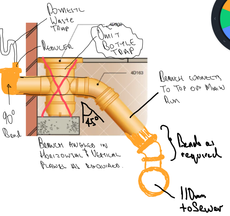
Thanks Dave That's very useful to know, helps my design along. So I imagine my other arrangement will remain for RWPs and the version below (if I have interpreted correctly) will works for domestics
-
Looking to do a sanity check on the drainage arrangement above as its one I'd like to use in my current project. Do I understand correctly that the domestic waste traps (kitchen sink, DW and washing machine) can be directly connected to a main sewer run via a suitable sized reducer on to a 110mm branch? I imagine that the reducer provides a sealed connection and the trap on the domestic waste prevents foul gases escaping?
-
I will have a browse through AD H, I'll be running my plans, once firmed up, pass my BCO as well. My reasoning for angled the branch in both planes was purely if needed to make the connection given the narrow spacing I have to work within but as you rightly point out it probably would be beneficial in terms of aiding flow regardless.
-
As part of my renovation work I am installing a new 110mm sewer run with various connections to an existing manhole. The most upstream connections (2x WCs) have been made and now the run routes down a side entrance to meet the existing manhole. Being a side entrance the width of ground I have to lay pipework in is limited to ~800mm, however along this section of the run I have to pick up a RWP and the usual domestic wastes (DW, washing machine and kitchen sink) The current plan is to use bottle traps to connect these various wastes onto the main sewer run. (Edit to add the current system is combined and BC have ok'ed combining all wastes) The narrow width combined with a relatively deep invert level (~700mm), means I think the bottle traps branches would have to be laid inclined at a 45 degree angle downwards (certainly in the vertical plane and possibly in the horizontal plane) so they can connect to the top of the main sewer run; as opposed to a side entry connection I'm unsure if that top entry connect is typically done or if it could be a problem, hence I'd appreciate any comments or advice on my plans. TIA Sketch below to help illustrate how the connection may be made:
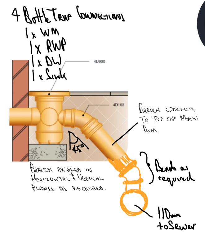
-
Fine tuning my IWI Solid wall (Warm Batten) design
Annker replied to Annker's topic in Heat Insulation
@jayc89 Thanks for your reply, your comment here and on previous threads have been very helpful I will be plasterboarding and beading the entire house myself (I'm a carpenter by trade). I'm doing this as I want the plasterer on the job to solely focus on skimming, which will hopefully result in a good finish. As such I will be dot and dabbing plasterboard to the internal walls, I suppose I can integrate the Contega PV behind that D&D boarding, sealing the tape to the wall by pasting board adhesive on and over it. With the hemp plastering, am I correct to picture that you ran the PIR down/up to the top/underside of the joisting and then applied the hemp plaster between the joists? That seems like a neat solution, my only question though is doesn't the hemp introduce a vapour open surface among a vapour closed solution? (I believe you had a similar query in your own thread) Also, you had considered applying boron to the pocketed joist ends, did you do so? I google finds this product which seems suitable however I'm unsure how effective application can be as the joists ends, which are most in need of protection are buried with the walls. Regardlesss perhaps just applying over the first couple of inches of the joist within the room will help. -
Following on from my previous thread I'm planning to start IWI installation on my victorian renovation in a couple of weeks time. My proposed buildup: Existing Solid 9" brick external wall 60mm foil backed PIR (Will serve as VCL) 35mm timber battens/service cavity. (Fixed to brickwork with concrete screws) 12.5mm plasterboard Gypsum skim coat I'm generally confident this arrangement will perform in my particular situation, however there are some junctions where ensuring vapour/air tightness is maintained at the VCL will be tricky. For example the VCL will be repeatedly penetrated by the batten fixings, furthermore the battens being fixed plumb may not be tight against the PIR along the entire length of the batten; my solution: Foil tape all batten edges to the PIR. However there are some interfaces jumping out as needing attention that I'm not certain how to best deal with: external wall to internal cross wall junctions: I imagine there is a tape by Siga or a similar manufacturer for such junctions, appreciate if anyone can recommend such a product? bottom of external wall this will be somewhere within the cellar (I will be running the PIR down below GF joist level), again probably will seal the PIR to the wall with a suitable tape top of external walls here I'm sure if I should just terminate the PIR/VCL at the roof wallplate, (perhaps taped to the wall plate) or should it be connected to a VCL installed to the bedroom ceiling joists external wall to intermediate 1st floor/ceiling. I don't believe any addition VCL is required here as I have re-joisted much of the house and stood the joists 70mm of the external walls where they run parallel to them, to allow the PIR run unbroken from cellar to roof. Any comments or critique greatly appreciated.
-
From reading here I know some people are fans of BIGT. Perhaps I don't fully understand their function but doesn't the BIGT still have to connect to the main drainage run via an Inspection chamber? I understand the BIGT provides a trap but is it not easier to provide the trap internal of the sink waste?
-
I suppose that helps that rodding and resulting wastes is outside the building.
-
Opinions please on this quote for substructure & drains.
Annker replied to Tony L's topic in Foundations
On the face of it I wouldn't think that price is hugely off the mark, there is a significant amount of work and materials. Have you other quotes to compare against? I'd also keep in mind that costs reliant on ground conditions should only be considered an estimate. Be prepared for the BCO, on inspection of the dug foundations, now requiring 1.5m foundations and 1m of concrete, or such & such. You need a contingency set aside for groundworks. -
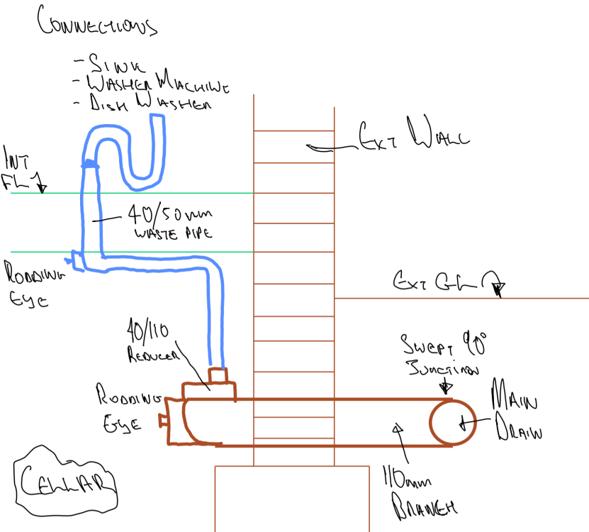
Looking for some design feedback. I have serval waste connections to make at ground floor level. Kitchen sink, disk washer and washer machine. Previously (many years ago) I would have just ran the 40mm waste through the external wall at high level (~1m) and then connected to the main 110mm drain run via a gully trap. I understand this arrangement is currently considered old school but regardless it is not suitable on this current job as I cannot have external surface fixed pipe work at this location. Reading previous topic I have came up with the design below. I'd appreciate if anyone can critique or suggest improvements. TIA.
-
Block and beam over ground beam
Annker replied to AdaminCymru's topic in General Construction Issues
Respectfully, I don't think that your builder or this forum are qualified/positioned to answer "is this ok", this should be raised with your SE and BCO. They will propose options which I'd then ask for the opinion of builder/forum. Nonetheless without knowing the specifics of the structural design I would doubt that the B&B floor has been designed to have the internal leaf blockwork (and its associated loads) built on it in that particular location; in practical terms it may be structurally sound however you may be committing the act of "not built to manufacturers specifications" so be aware of the risks that may bring. Was the builder responsible for forming the ground beam incorrectly, because that is a silly mistake, and not something I would consider fine. It is a big f up plain and simple. -
@Mr Punter and @Marvin, thanks for the comments. Yes I did have the thought that separating the shower wastes from the WC branches would be a better arrangement although I also thought that with them being at more or less the same level as the WC their respective junctions on the SVP would clash with one another. One way avoid that clash would be to put a 90 deg elbow on the shower wastes after they penetrate the wall and them return them into the SVP at a lower position. That would introduce another 90 deg bend in their route but perhaps it is still a preferable arrangement to having them T into the WC branch, which as pointed out may not be possible in any case.
-
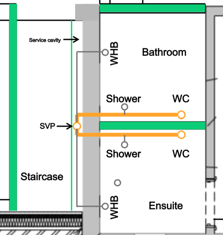
Spent the better part of the day researching many post here and I think I have figured out some more detail to the design. To try simplify the things I have separated the downstair WC and WHB from the upstairs sanitary waste; both will join into the inspection chamber through individual inlets. This also build in some redundances into the house, should blockages occur The upstairs draining is the more complex and I would appreciate any feedback offered to my sketch below. The WC's will be "back to wall" with a "P" type trap. A 90 deg rigid pan connector will join the pan to the 110mm branch pipe which will pop up through the floor. I also have the shower waste connected into this branch pipe, unsure if that is ok, in theory any whether it is possible in practical installation terms either? The 110mm branch pipes will penetrate through a brick wall into a created service cavity. Both branch pipes will then both connect to a single SVP via a double branch. I then have the WHB's exiting their respective bathroom in 50mm waste pipe and connecting to the SVP via a double boss branch above the WC double branch, my understanding is this is a preferred arrangement. Any feedback greatly appreciated!
-
Dear all, I would appreciate some help with designing a bathroom, ensuite and WC waste drainage layout in my renovation/extension project. As illustrated in my markup I will have a downstairs bathroom (WC & WHB), bathroom (WC,WHB & shower) and ensuite bathroom (WC,WHB & shower) all located on the other side of the existing wall. The plan is that all waste drainage will penetrate this wall and go to GL within a created service cavity, within the (yet to be built) extension block. At GL the drainage will be ran underneath the extension suspended timber floor, and exit to a new chamber. My question is can these various wastes all join into a single main drainage stack (which will be vented through roof level) and a single drain run to the chamber, or should each bathroom have its own stack and multiple drainage runs into a distribution? chamber. For simplicity have not included ~2 RW downpipes which were originally combined into the sewer drainage. I'm unsure if BC/Bregs allow combination of RW and sewer in renovation work but I will confirm with my BCO. Extension drainage schematic.pdf



