MortarThePoint
-
Posts
2198 -
Joined
-
Last visited
Everything posted by MortarThePoint
-
Sink, bath and shower wastes in concrete floor
MortarThePoint replied to Triassic's topic in Waste & Sewerage
Yes, but was this because of using a concrete pour rather than a screed? -
Sink, bath and shower wastes in concrete floor
MortarThePoint replied to Triassic's topic in Waste & Sewerage
Cool shower waste. You did go for UFH under the shower. Was you floor concrete with rebar? -
Sink, bath and shower wastes in concrete floor
MortarThePoint replied to Triassic's topic in Waste & Sewerage
I don't know why but I had presumed the UFH would not extend under the shower. I'm not sure I'll do it. Other than your good point about the trap, I can't think of any pros or cons as the shower water will be hot. -
Sink, bath and shower wastes in concrete floor
MortarThePoint replied to Triassic's topic in Waste & Sewerage
Is it standard to have UFH under shower trays? -
Looks the part. At £5/m2+VAT I'd rather DITRA though even if it's a little more expensive.
-
Is anyone else buying their screed at the moment? I'm typically being quoted about £350/m3+VAT installed based on 11m3 for Annydrite liquid screed, does that sound market rate? Not normally part of my daily shop, so less confident than some of the other commodity items.
-
Some options here: https://www.protilertools.co.uk/categories/materials/tile-matting Durabase is thicker (4mm) than DITRA (3mm) and about 10% cheaper. There are a couple of uncoupling mats that are less than 1mm thick and quite cheap (<£5/m2), but that's not much room to do a good job of uncoupling. If @nod used DITRA on his own house I think that says a lot.
-
Just reinforcement I think: https://products.kerakoll.com/en-GB/p/biotex
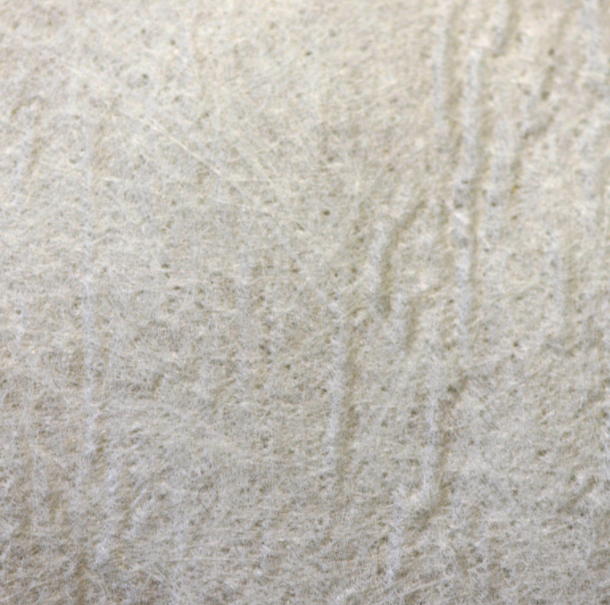
-
I don't know if the stuff below is any good, but I guess it doesn't decouple. Only £2.87/m2 though. "Kerakoll Biotex Anti Crack Matting is a reinforced anti-cracking sheet matting, for evening out tensile and sheer movements between the substrate and the surface finish. Also suitable for use as an anti-cracking product for tongue-and-groove hardwood floors on critical substrates. For internal floors. Previously known as Kerakoll Idrobuild Tex Matting" https://www.tilingsuppliesdirect.co.uk/product/kerakoll-biotex-anti-crack-matting#.YKO0bahKhaQ
-
I couldn't find it on the website either so called. DITRA 30m roll for £6.67+VAT / m2 as a starter. Thanks @nod.
-
This is one of those potentially overlooked costs. Can you get away without it, possibly. Would you kick yourself if you didn't use it and had an issue, definitely. As a self builder you have enough to worry about, so worth including. It does seem rather costly, but maybe I am looking in the wrong place. Looks to cost around £6/m2 or above. You have expensive tastes. Just joking, but it must be very good as I can't find it for less than £10/m2.
-
Your installers did better than mine then. Like I said, I chalked this up as a Covid consequence though as I'd have been all over it otherwise.
-
Yes that could work nicely. If I tucked the rebar into the core hole on the right hand side and onto the beam on the left hand side it would all hold well. Alternatively, I am thinking of leaving it to have OSB3 and SLC over the top and using the hole as a possible 'conduit' to route things along the landing as there is a smaller hole at the other end too. The SLC would be minimum 20mm thick which meets the requirements of most over timber (e.g. Weberfloor Flex or Weber 4310). Covered in carpet any small cracks at the SLC/screed interface wouldn't matter. Not so sure what I'd send along there though.
-
You also end up with some unintended openings. I have to work out how to close this one (200mm wide) within the 40mm of screed depth that is going over the top.
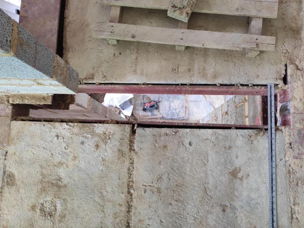
-
Interesting reading. My experience has taught me two things: 1. At spans under 5m you can have big holes knocking out two steels with no issue. 2. When they install them it is easy for the planks to drift out 50mm or so in the direction perpendicular to span, putting your opening in slightly the wrong place. OK for services a pain for something like a chimney (I had a 700mm chimney passing through the join in two planks and had to shrink the chimney to 650mm). Make a checklist of dimensions to be checked as they install. I'd have been all over them if it hadn't been for Covid. 3. You'll forget some holes. Haven't tried drilling anything larger than 25mm, but that was very easy.
-
Not ideal, but I would have to have a box channel to pass the pipe along the wall that would need to be internally 40mm above finished floor and externally around 50mm above finished floor depending on the finish on the box channel.
-
Hopefully a simple one that many have had to think through before, but what is the minimum distance between underside of waste pipe or trap (whichever is lower) and top of shower tray? We have concrete planks and in most places I have made allowance for a trap to sink into the the floor and pipe routing. However, we are changing the configuration of an ensuite that just didn't previously work. Consequently, the hole I have left in the concrete is no longer of use. The horizontal run is just less than 3m, so I think that means I can use 40mm pipe which would have to fall at minimum 18mm per metre and would make for (3*18mm) + 43mm = 97mm for just the pipe. Using a trap like the one below would make for a total height to underside of tray of 58mm + 54mm = 102mm. https://furniture123.co.uk/p/wirquin-90mm-slim-shower-waste-dome-waterseal-30120026 Does that all look correct? My screed height is 40-45mm and the tiles etc will raise the floor finish up to around 60mm. That means the underside of tray only needs to be another 42mm higher than that. Looking at a suitable shower tray The top of the kerb would then be 40 + 42 = 82mm above the top of tile. In reality this would be more like 90mm to allow some wiggle room. Does that sound typical / acceptable? This may sound strange, but I have never owned a walk in shower before, so have no idea on what feels right here. Always only had a bath with a shower over.
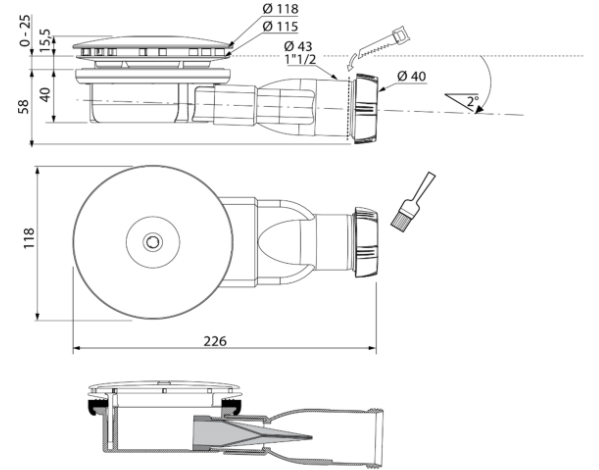
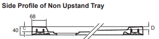
-
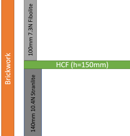
It's on the first floor but above concrete (HCF) floor planks that rest on the inner leaf.
-
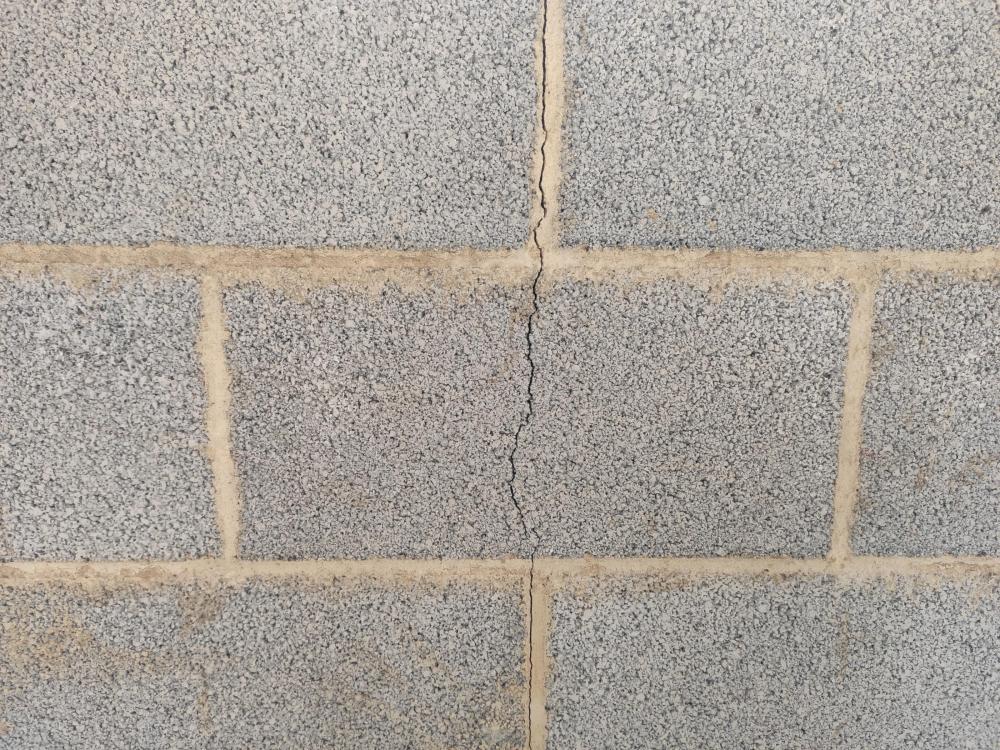
For reference, I have had some cracking of blocks under 1.8m wide windows (near middle of window). Hopefully this is just shrinkage, but I thought I would share it on this thread as it was one of the Fibolite considerations. I suspect if we had used a layer of bed joint reinforcement in the bed just under the window this wouldn't have happened, but ultimately the shrinkage has to be accommodated somewhere and arguably under a window is the best place (?). This photo shows the worst of it (so far, but 6 months after being laid).
-
Chimney DPCs and damp handling
MortarThePoint replied to MortarThePoint's topic in Stoves, Fires & Fireplaces
For mine, the flue liner just passed through the hole unabated (i.e. the lead all sits outside the liner). In severe weather areas it is supposed to come inside the liner though. -
Is UFH for bathrooms worth it?
MortarThePoint replied to MortarThePoint's topic in Underfloor Heating
@joe90 or @Bitpipe if you had to guess, how much height would you leave for the electric UFH and accompanying self levelling compound? For me this would be on top of a screed over concrete. I'm guessing I need to allow 6mm for the electric UFH and self levelling combined, but would value your experiences there. That would mean on top of the screed I'd have roughly: 6mm self levelling compound including electric UFH wires 3mm tile grout 6-12mm tiles So up to 21mm. -
Stiffening subfloor with floating noggins
MortarThePoint replied to MortarThePoint's topic in General Flooring
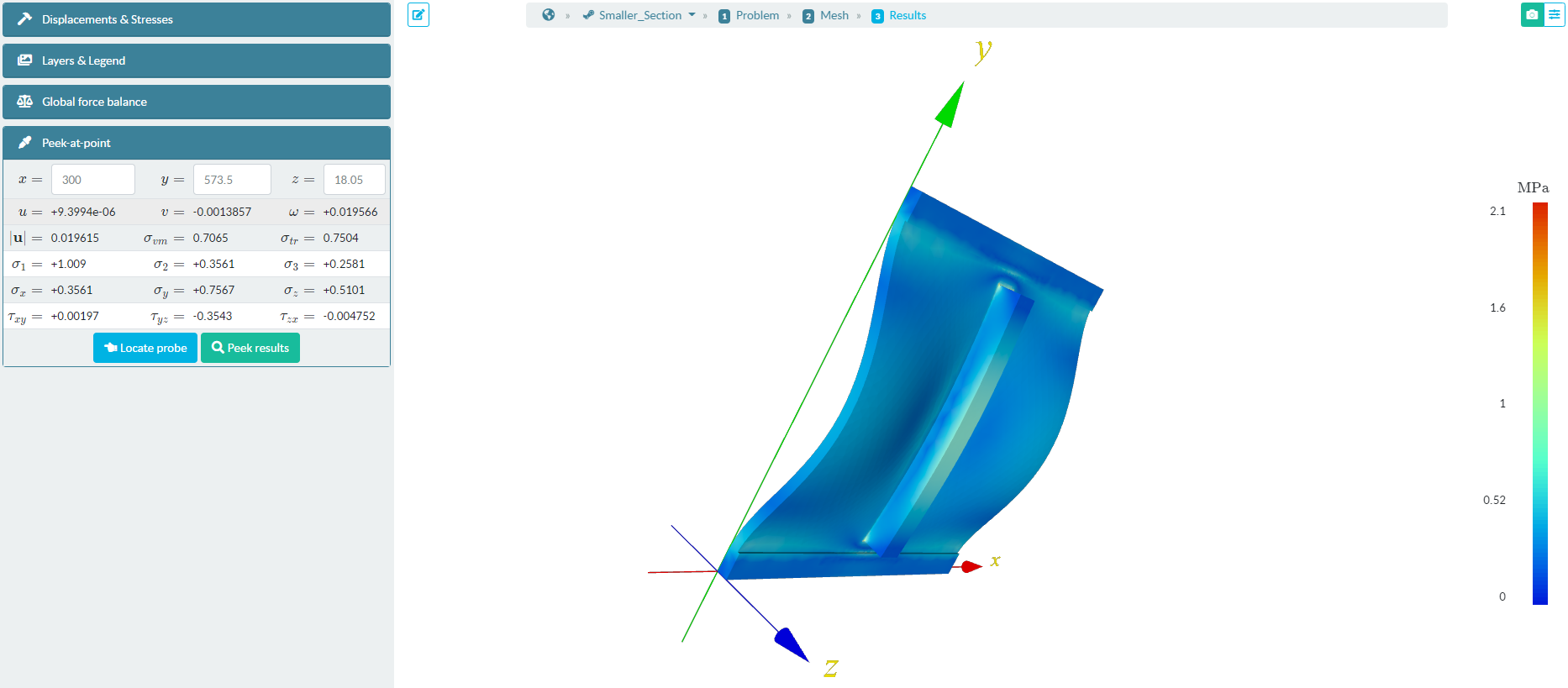
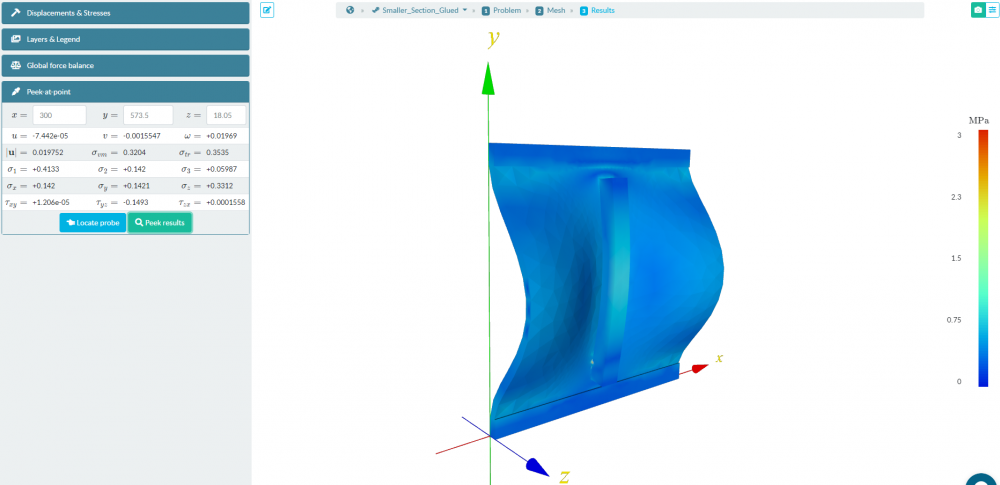
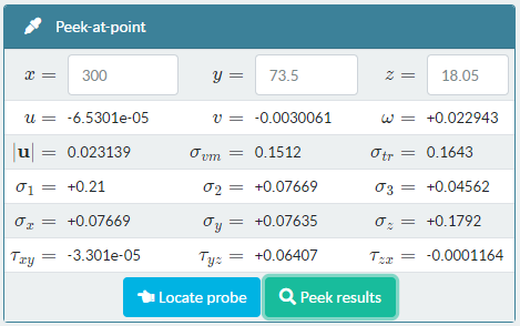
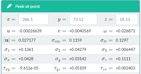
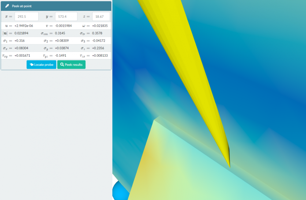
For reference, the glue tensile stresses in the non-45 degree cut 47 x 47 case at the end of the rib where I expect it to be highest are: Not modelling glue layer: 0.51MPa [global max stress was 2.1MPa, not sure where] Modelling the glue layer: 0.33MPa [global max stress was 3MPa, not sure where] Both of these are higher than the OSB3 out of plane tensile strength (0.3 MPa) so would be an issue. Modelling the glue layer and approximating the 22 x 100 gives a glue tensile stress of 0.18MPa. I'm not trusting that value as the solver is doing something weird and violating symmetry (circled). That needs to be halved though due to the way I am modelling the dimension change and so the value becomes 0.09MPa, well under the OSB3 out of plane tensile strength of 0.3MPa. Note, peak deflection in that model is 0.3mm. A hand waving argument would suggest the stiffness per unit width of the rib has gone down to (22/47)^3 = 10% and the glue stress should too for the same displacement. Displacement there will be higher by a factor of (47/22) ~ 2 higher and so the glue stress should be about 20% of the 47 x 47 case. That supports a figure of around 0.06 to 0.1 MPa, under the OSB3 out of plane tensile strength of 0.3 MPa. 22 x 100: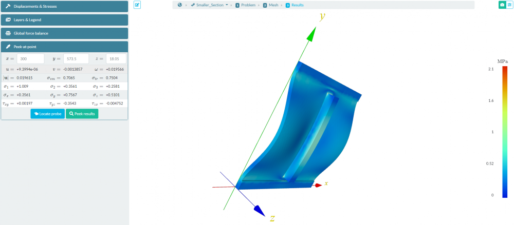

-
Stiffening subfloor with floating noggins
MortarThePoint replied to MortarThePoint's topic in General Flooring
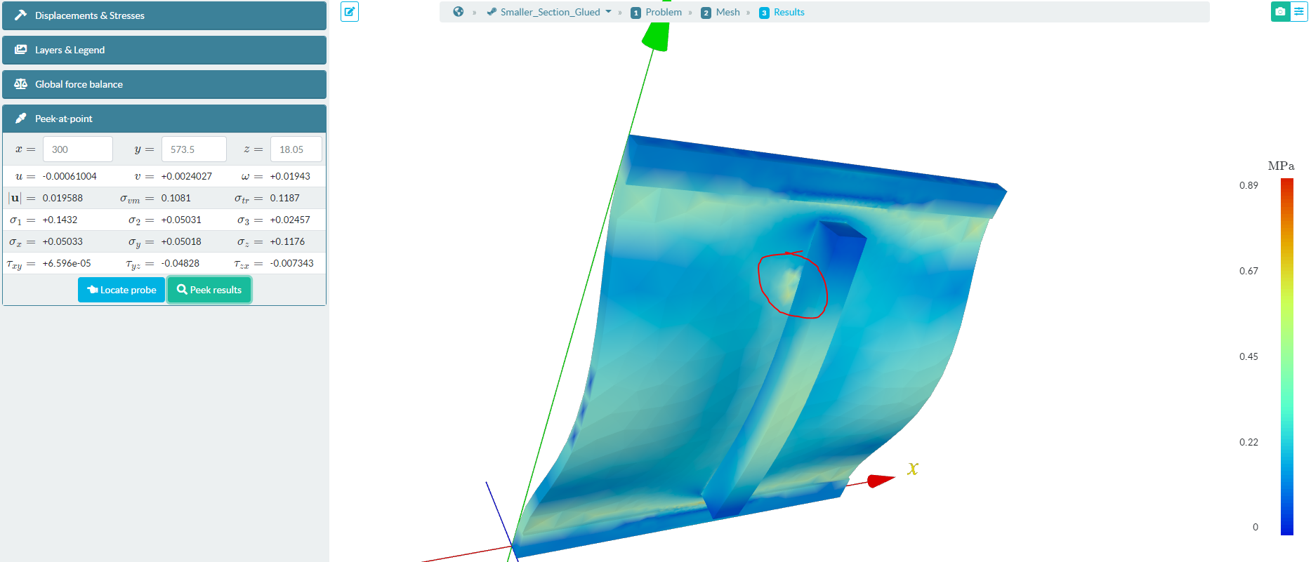
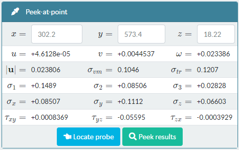
I thought I would investigate other timber sizes acting as ribs. I have a limited number of models I can simulate, so am doing this by modifying the Young's Modulus with the cube of thickness and linear with width: E' = E * (w/47) * (t/47)^3 This doesn't very well represent increases in width as the curve of the sheet deflection would be supported further out in the x-direction, so this would give an overestimate of deflection in that case. Using 22 x 100 timber (E' = 1.6GPa) still has a meaningful effect and reduces peak deflection to 0.35mm (0.25mm with a fixed noggin, 0.3mm with 47x47 and 0.52mm with nothing). Using 38 x 50 timber (E' = 4.5GPa) gives peak deflection of 0.31mm (0.25mm with a fixed noggin, 0.3mm with 47x47 and 0.52mm with nothing). Using a piece of 25 x 38 batten (E' = 0.97GPa) gives peak deflection of 0.37mm (0.25mm with a fixed noggin, 0.3mm with 47x47 and 0.52mm with nothing). So strengthening the long edge joints with even 22x100 timber sections looks to give a significant improvement in stiffness, reducing peak sheet based deflection by 33%. I expect adding another rib mid panel would reduce peak sheet based deflection much further too (below 0.2mm as even in the weakest case above, the deflection above of the 38x25 timber was only 0.2mm), probably reducing peak sheet based deflection by over 60%. If I can be bothered with any of this, I think I would go for 22 x 100 at the joints and perhaps 25 x 38 at the panel midline. I expect that would make the sheet immensely stiff, without putting undue out of plane stress on the OSB3 (No Guarantees though :-).
-
Stiffening subfloor with floating noggins
MortarThePoint replied to MortarThePoint's topic in General Flooring
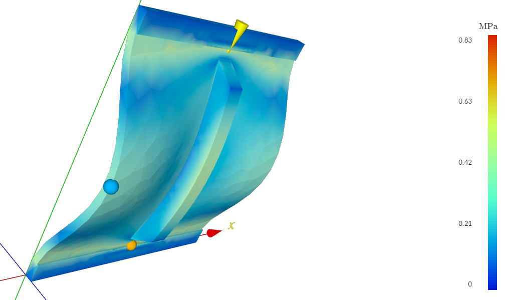
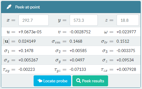
I've tried the 45degree cut. To aid visualisation, I increased the glue thickness to 1mm, but not changing its MOE. The maximum displacement is now 0.33mm, but the peak tensile stress is much reduced (if it is to be believed) to 10% of the OSB3's out of plane tensile strength. The maximum displacement is 0.33mm. Increasing the MOE of the glue by a factor of 10x to compensate for the increase in thickness (therefore giving the same deformation) puts the deflection back to 0.30mm, but the peak tensile stress to 0.24MPa which is 80% of the OSB3's out of plane tensile strength. The 45 degree cuts help and using a more flexible glue would definitely also help. Glue stiffened to counteract effect if increase thickness used for visualisation:

-
Stiffening subfloor with floating noggins
MortarThePoint replied to MortarThePoint's topic in General Flooring
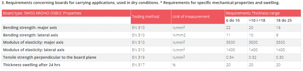
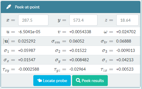
As feared, the tensile strength of OSB3 perpendicular to the board plane is poor. Below is example data for something I could find and it's only 0.3N/mm2 = 0.3MPa. I think the peak stress applied to the OSB3 in this fashion is around 4x that figure. The screw could help, but it would be better of the material properties were compatible with just the glue. It occurs to me that the stress could be reduced by having a 45degree cut at the end of the splint. I don't know if that would be enough though as that out of plane strength is very low.