MortarThePoint
-
Posts
2168 -
Joined
-
Last visited
Everything posted by MortarThePoint
-
Cheap (and accurate) temperature data logging
MortarThePoint replied to dnb's topic in Boffin's Corner
Sounds interesting. Why do you want differential pressure? Is it to minimise air leakage? -
Cheap (and accurate) temperature data logging
MortarThePoint replied to dnb's topic in Boffin's Corner
Nice part. I have used some parts like BMP180 before and these pressure sensors are very precise. Have you found a use for the pressure measurements? -
Cheap (and accurate) temperature data logging
MortarThePoint replied to dnb's topic in Boffin's Corner
Thanks. I have ordered 5 to have a play. I am also considering MAX31820. Similar sort of deal, except on Farnell or RS (reliable) they are half the price of DS18B20 and the +/-0.5C accuracy range is limited to +10C to +45C. That should be fine for indoor applications. £1.68 at 10 off. May not work with standard libraries but should be easy to port. A bunch of these on telephone wire covered in rubbery potting compound or some flexible grab adhesive should work nicely. Please note: big difference is working voltage 3 to 3.7V so wouldn't work with 5V Arduino. Laid ready for screed to go over could be asking for the screeder to kick the wires though. https://uk.farnell.com/maxim-integrated-products/max31820mcr/temperature-sensor-2deg-c-to-92/dp/2515555?st=max31820 https://uk.rs-online.com/web/p/temperature-humidity-sensor-ics/1905324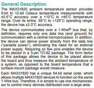
-
Cheap (and accurate) temperature data logging
MortarThePoint replied to dnb's topic in Boffin's Corner
I'm keen to get some of these probes. How do you know they were genuine? Did you read the serial numbers etc? -
I've been thinking about embedding some DS18B20 temperature sensors on a network. They're about £4 each. Fakes are much cheaper (~50p) but cause issues which is a shame as at 50p a pop I'd litter them everywhere. https://create.arduino.cc/projecthub/TheGadgetBoy/ds18b20-digital-temperature-sensor-and-arduino-9cc806
-
UFH manifold cabinet - any point?
MortarThePoint replied to MortarThePoint's topic in Underfloor Heating
They didn't question that. Where would the bypass go, across each manifold or in parallel with the three manifold circuits? -
UFH manifold cabinet - any point?
MortarThePoint replied to MortarThePoint's topic in Underfloor Heating
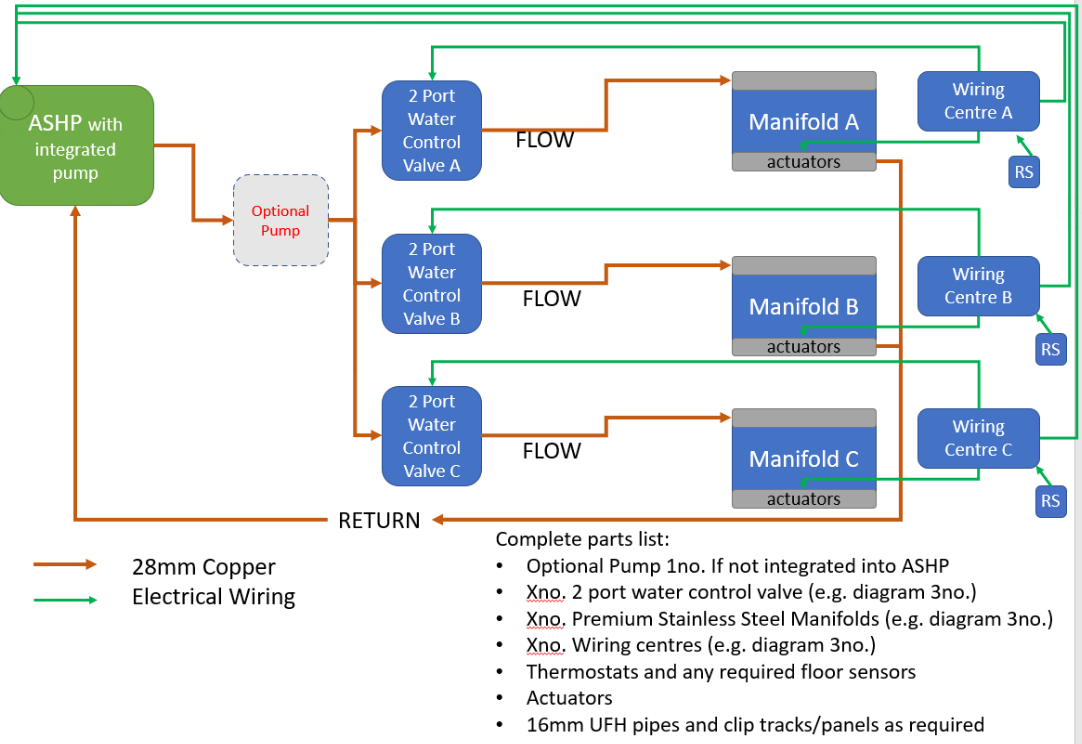
I'm going to leave enough space to fit a pump set on each manifold. The plan (which may be wrong) is set out in the diagram below which I shared with WUNDA. Three prallel circuits each with their own 2 port control valve but one or no additional pump. I have wondered how the flow is regulated into each parallel branch given two of the manifolds have 10 or 12 ports used and the third only 3 used. If it's all pressure driven, then the parallel configuration should be OK with one pump, perhaps integrated into the ASHP.
-
UFH manifold cabinet - any point?
MortarThePoint replied to MortarThePoint's topic in Underfloor Heating
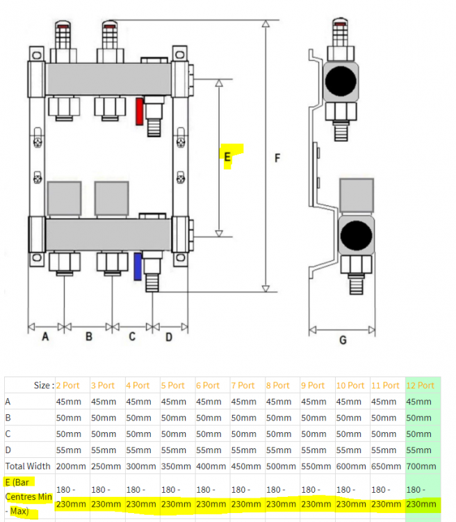
I shouldn't need any pumps at the actual manifolds (ASHP setup), but I would like to space my bars appropriately should I need to retrofit. Looks like that means I'll have the bars at their maximum spacing of 230mm.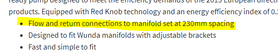
-
UFH manifold cabinet - any point?
MortarThePoint replied to MortarThePoint's topic in Underfloor Heating
Don't quite follow what this is saying. What does "Trimmer between walls mean"? https://stairs.bwf.org.uk/wp-content/uploads/2014/10/Toolbox-talks-SPLIT-5.pdf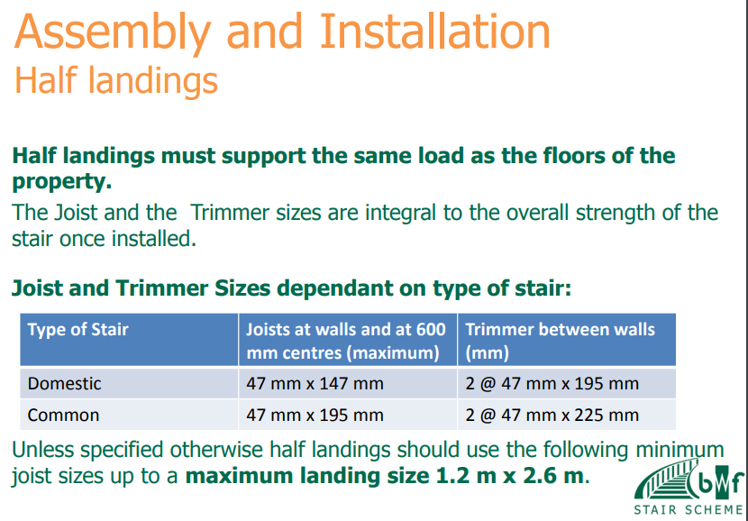
-
UFH manifold cabinet - any point?
MortarThePoint replied to MortarThePoint's topic in Underfloor Heating
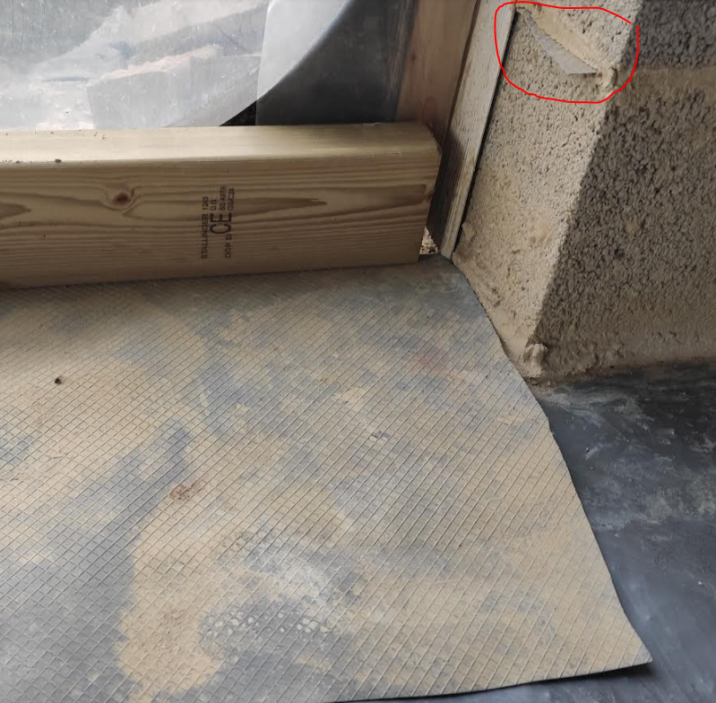
Thanks! Do you know what the section of the timber labelled with the red arrow below is? 4x2, 6x2 or 8x2? Have you mounted your manifold on a board (if so of what) or neatly not painted an area?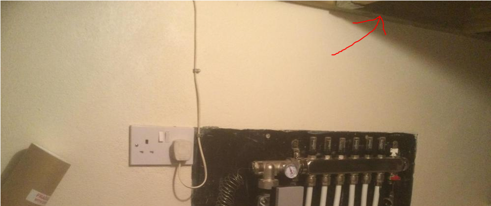
-
UFH manifold cabinet - any point?
MortarThePoint replied to MortarThePoint's topic in Underfloor Heating
Straight from the WUNDA installation blurb. To allow space for connecting and disconnecting all the pipes I guess.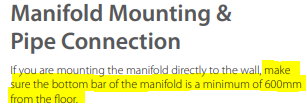
-
UFH manifold cabinet - any point?
MortarThePoint replied to MortarThePoint's topic in Underfloor Heating
Under the stairs I think I'll struggle a little for height as 6 steps to the half landing this will be under. That means only 1200mm of space and the bottom of the manifold needs to be 600mm above FFL. Here's hoping the stair timber will be 200mm or less. I could mount (hori or vert) a couple of pieces of 4x2 to the wall and then put the manifold on that. This could allow a tiny bit more height, or if needed remove the top bit of 4x2 when installing the stairs and then screw the manifold to the stair timber. -
UFH manifold cabinet - any point?
MortarThePoint replied to MortarThePoint's topic in Underfloor Heating
I'll just be screwing my manifolds to the walls. In two places this will be blockwork walls so I anticipate using masonry screws like the ones below with some appropriate steel washers. When mounting on a studwork wall, should I use some form of vibration isolation as I could imagine the plasterboard acting as a sounding board. Screwed to the studs, but still. https://www.screwfix.com/p/easydrive-pan-concrete-screws-6-x-60mm-100-pack/9665r https://www.toolstation.com/masonry-torx-frame-fixing-screw/p16209
-
What goes under the door sill?
MortarThePoint replied to MortarThePoint's topic in General Construction Issues
Purenit (link) looks like good stuff. It's a bit late for me as I'm not sure I'd have space for anything over about 10mm thick sat as a bridge over the cavity and then masticed under the sill. Mocked up below. The Purenit would probably need to be bedded on something which would add an additional ~5mm. I don't know whether 10mm of Purenit would be stiff enough. I think the back of my door sill will be approximately 30mm behind the cavity edge and so the sill would cantilever 30mm and so the screed cantilever 70mm (100mm cavity). I'm looking at having a 50mm screed now, so maybe adding a small strip of mesh would be good. If there is a product like bed joint reinforcement that adds strength in two dimensions, not just one, that would be good to embed in the top of the screed to help with tensile strength.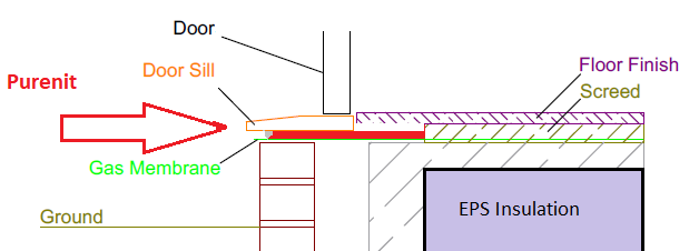
-
What goes under the door sill?
MortarThePoint replied to MortarThePoint's topic in General Construction Issues
Thanks, looks like a good arrangement. Is that a timber frame above ground level? Looks like very thick walls. -
What goes under the door sill?
MortarThePoint replied to MortarThePoint's topic in General Construction Issues
I asked and never got an answer about this from the Thermabeam guys Seems like everyone does some form of bodge where they rely on the screed to cantilever over the cavity a bit. LABC drawings call for a structural cavity closer or a reinforced cavity closer, but talking to cavity closer manufacturers there doesn't appear to be such a thing. This drawing shows a way of doing it, but still relies on the flexural strength of the screed as the cavity closer isn't structural: https://www.slideandfold.co.uk/alumina-low-threshold-with-cill.pdf Good luck drilling the 'External Brick Work' that close to its edge.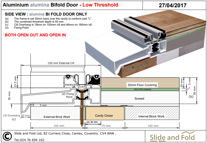
-
My Cavity closer should do that for me as the door frame won't extend further back than the cavity closer (will it)
-
Was that effectively covering the area I have shaded red there?
-
This doesn't make things much clearer, but I think it's saying there should be DPC under the door to stop rising damp https://www.labcwarranty.co.uk/blog/spot-the-defect-damp-proof-membrane/
-
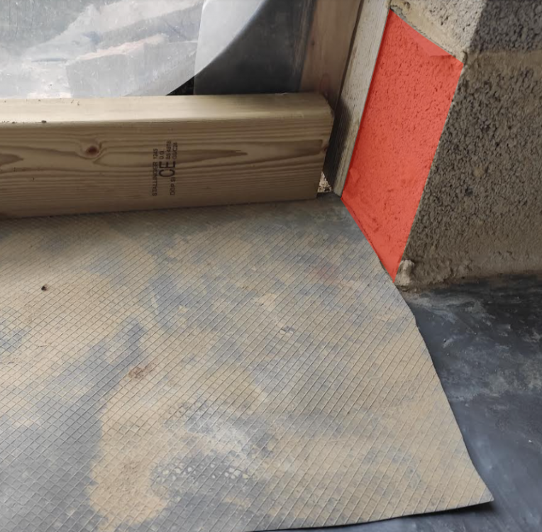
I'm not sure what I should be doing at the door thresholds in regards the Cavity Tray. Below is a photo. You can see the floor membrane which goes on to bridge the cavity and all the way to the outer face of brickwork. There is a cavity tray above the membrane and you can just see some of it jutting out of the blockwork (circled RED). The cavity tray has been cut to lie flat on the membrane in the door threshold. A 40-50mm thick screed is going on top of the membrane and the timber you can see is there as stuttering, with subsequent perimeter strip to be added. What should I do with the DPC? Should I tuck it out of the way so that I can then lay it onto the screed, or should I cast it under the screed? The plan will be to later use slate or something to cross the cavity under the door frame and then fill any gaps with Self Levelling Compound. Does this sound sensible, or is there a better option. The thresholds are not level, with a step up from the patio of around 125mm. That is except for the front door which is level, but under a porch so should be dry. As it's not a level threshold and will be under the sill I don't think this DPC really matters does it?

-
Looks good and very neat PIR insulation
-
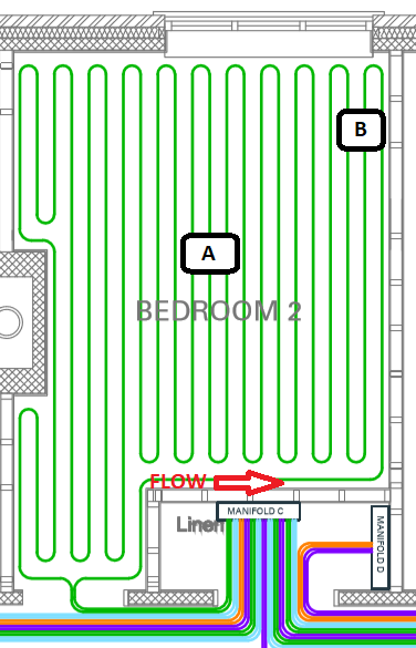
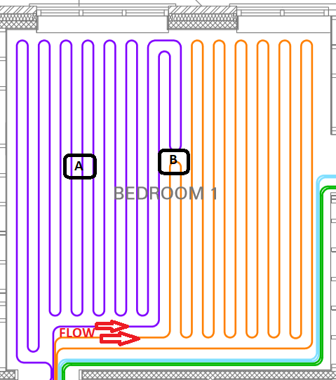
Easy when you know how! I'll have to avoid crossing over like you have as I don't have the mesh, but where I have serpentine pattern I can just go between two loops. I see you have put your sensor at the hottest point (B from my original post)
-
Cool, that allows fixing them if they break which is good. Can you recommend a type of pipe to use?
-
I've been getting my bits from WUNDA and wondered ( ? ) if their floor probes (aka Thermostat sensor) are any good? Being something that gets cast into the screed I can't change my mind later. Also, in terms of placement within the room. Should they be placed near the start of a floors circuit (B) or mid circuit (A)? Near the start makes sense to me as the purpose of the sensor is to protect floor finishes and so the hottest point needs to be detected, but I may be missing something. Finally, I also assume that the Thermostats can only take one temperature sensor input. @Nickfromwales Is the doctor in session?
-
Fan Coil Units for use with a (cooling) ASHP
MortarThePoint replied to ProDave's topic in Air Source Heat Pumps (ASHP)
This is cool, literally. If just looking to cool the floor, is it just a matter of having the right ASHP? Sending 15C water through the UFH pipes feels pretty low risk from a condensation perspective. If concerned by condensation on the manifold, one can always run a separate dehumidifier nearby or perhaps just a fan blowing over their surface.