MortarThePoint
-
Posts
2168 -
Joined
-
Last visited
Everything posted by MortarThePoint
-
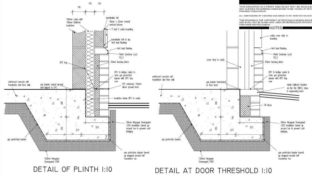
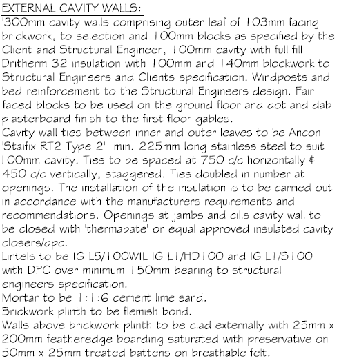
We're going with feather edge cladding (not the T&G shown below) above a brickwork plinth. The construction drawing detail calls for Code 4 lead, but the separate written specification document doesn't mention it. Is it needed? The Plinth stretcher bricks are actually headers but are Class A Engineering brick. The lead is a cost but also not a nice material if growing things near the garage. --------------------------------------------------------
-
I've heard some people say it's better to tile without the bath in place. What's the best approach here? The bath will sit in a timber frame so I could build that to provide an accurate reference for the tiler to hold the tiles back from.
-
The usual risks of Amazon apply, but here are some promising looking tapered options: 110/50 PP pushfit https://www.amazon.co.uk/Water-Reducer-Reducing-Sleeve-Übergangsrohr/dp/B01JH34JHA 110/50 PP pushfit https://www.amazon.co.uk/Ostendorf-175720-HTsafe-Reducer-Piece/dp/B075HXH9S5?th=1 also smaller pushfit 110/50 PVC solvent https://www.amazon.co.uk/sourcing-map-Reducing-Coupling-Connector/dp/B07KZDWMBQ For those wanting to adapt from 40 to 50 without losing too much height: Aquaflow offset https://www.toolstation.com/solvent-weld-reducer/p27594 (Polypipe make an equivalent too) Polypipe WS59 (best option) https://www.polypipe.com/housing/above-ground-drainage/waste/solvent-weld-waste-system-abs/reducer-40mm-50mm-ws59w Unknown ?double socket? https://www.victorianplumbing.co.uk/2-x-1-5-waste-pipe-reducer
-
I need to fit a shower tray with its underside about 50mm above the screed for most of its area. There is a hold back in the screed in the area of the waste so deeper in that area, but I can happily mortar in bits of paving slab onto the hollowcore concrete floor there. Most legs have a minimum height greater than this and require a sheet of plywood too. What would you recommend? Options that I am considering already: Mortar down 35mm thick paving slabs. With a 7.5mm bed of mortar below the slab and 7.5mm bed of mortar between the slab and the tray I'll hit the 50mm required. Will have to cut some curved slabs which could be tricky. Make a timber frame out our 50mmx25mm battens and put 18mm plywood over the top of that. Then a 7mm bed of mortar will hit the 50mm required. Not too keen on adding a load of wood underneath in an otherwise all concrete setup Find a 1100mm x 800mm left offset quadrant shower tray that has space underneath and can have a hole cut in its skirt. Not sure such a thing exists Any suggestions for what I should dress the raised edge with? i.e. between the tray and the floor tiles
-
Notch underside of joist?
MortarThePoint replied to Sparrowhawk's topic in General Construction Issues
Assuming there is no wall or unusual load above, a 6x2 would likely be sufficient for a 3m span anyway https://nhbc-standards.co.uk/6-superstructure-excluding-roofs/6-4-timber-and-concrete-upper-floors/6-4-8-timber-joist-spans/ It's all looking promising. Also, this joist is carrying (34cm/2)+2.5cm+6cm = 26cm of floor where all the others are carrying 40cm. -
Notch underside of joist?
MortarThePoint replied to Sparrowhawk's topic in General Construction Issues
How deep would you notch be at its deepest? Your image suggests about 25mm -
Notch underside of joist?
MortarThePoint replied to Sparrowhawk's topic in General Construction Issues
https://www.labc.co.uk/news/how-get-it-right-notches-holes-solid-timber-joists Lots of US guidance has notches in bottom as well and there the rule is maximum depth D/6 and maximum width D/3 and avoid square edges (where D is the depth of the joist). On that basis a 1" deep notch wouldn't be a problem. Not in the middle third of the joist span though. I know US code is irrelevant to the UK, but it sometime provides me with some comfort. Your image makes it look like you'd only be shaving a small amount off. Perhaps a triangle that is 1" x 1". That means that you are leaving 75% of the material that would be cut out by a full width 1" deep notch. Should be fine, especially given it is so close to the wall and therefore not supporting as much floor above as an ordinary joist. -
Notch underside of joist?
MortarThePoint replied to Sparrowhawk's topic in General Construction Issues
What is the distance between the joists? -
Do you think it would be an issue if the 50mm pipe entered the 110mm pipe at the bottom rather than at the top as you have it?
-
It looks like this joints at the top of the 110mm pipe rather than middle or bottom. Do you happen to remember who makes that adaptor?
-
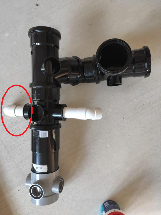
@Nickfromwales Jethro may have made a whoopsie on this one. I'm worrried that the 40mm pipe entering the stack circled in red is a problem for two reasons: It's 180mm rather than min. 200mm offset from the 110mm branch entry from the WCs. Does the Floplast SP190 Branch count as swept and mean I'm OK? It is directly opposite another 40mm pipe. I think I've seen a fair few other setups like this though or am I imagining it? Am I right to worry, or do you think it's all within the slack of interpretation?
-
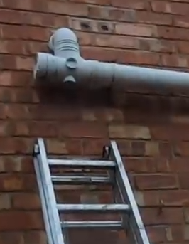
This is what I'd want to avoid. In this case the blockage is in the pipe that is going into the wall and down into the branch orientated on its back. Pretty impressive! Before removing the access cap:
-
Good thought. It's a pig to route the shower to the stack separately unfortunately hence the whole use of the branch. I think I can include an AAV (Class A1) on the shower's 40 or 50mm pipe to ensure the trap doesn't empty.
-
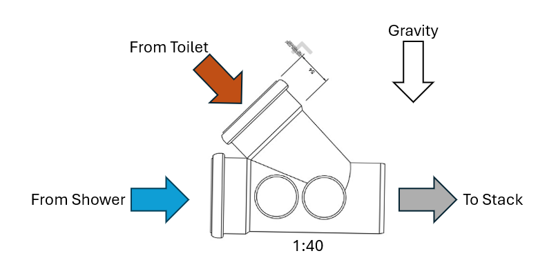
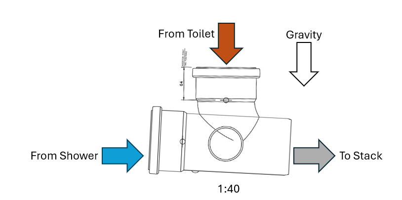
Is it OK to install a branch as shown below? I can see that there is probably a violent flow within the branch from the toilet direction and wonder if that could cause solids to get left behind or anything. In my specific instance: 'To Stack' end is probably straight into a 90 bend 'From Toilet' would be a 45 bend and some 110mm pipe with then a pan connector inserted like WC-CON8 'From Shower' would be a short length of 110mm pipe (~200mm) and then 40mm or 50mm pipe. I don't want the 'From Shower' side to get blocked by solids left from the 'From Toilet' bit. I assume the following configuration is less desirable than the first:
-
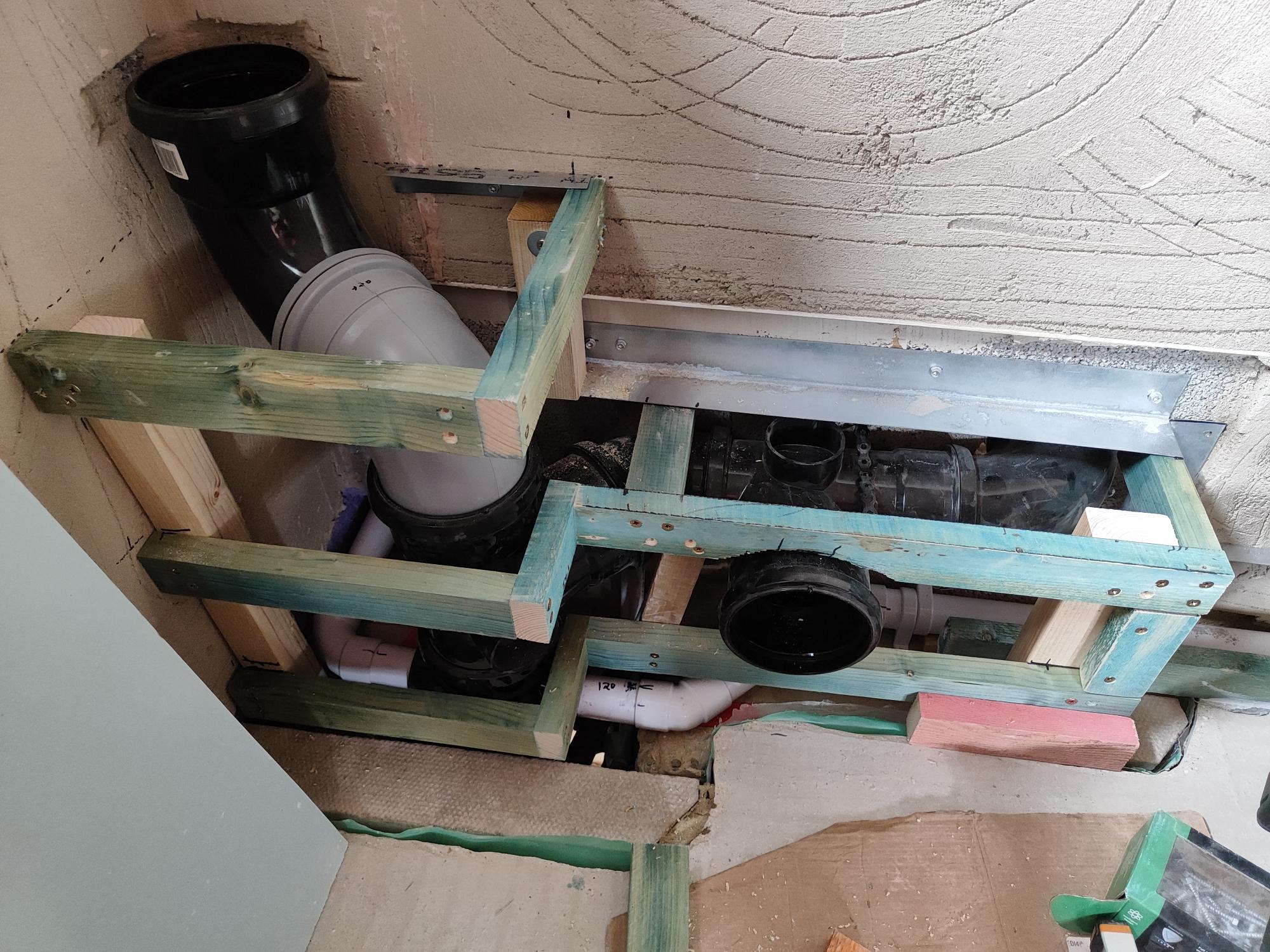
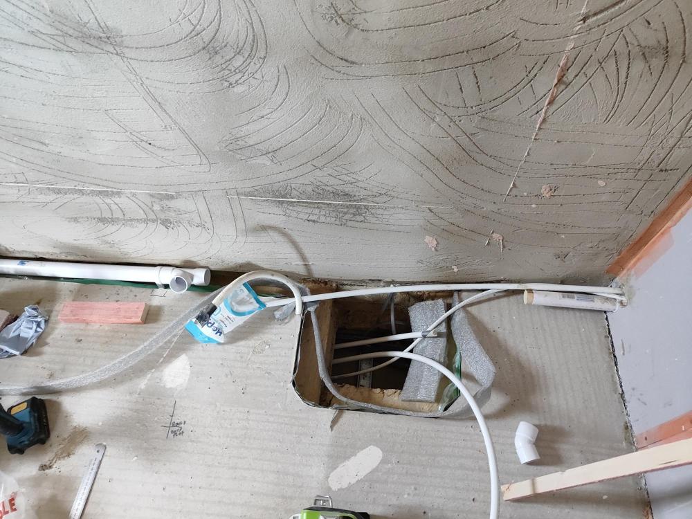
Below is a picture of how all of this as ended up. You can't see that below HCF there is the 50mm shower waste joining, but just above the HCF you can see the two 40mm waste pipes (bath&basin from this room and shower&basin from next room). Also out of view is a 32mm pipe that forms a possible future connection point for a loft toilet (via macerator). The grey and black 90 elbows bring the stack to the wall and an AAV goes into the top. On the right of the image, you can see the 90 bend going into the wall for connection to the toilet in the next room. Around the middle of the photo is the connection point for this room's toilet. Rodding access is perhaps not as good as I could have done (90 bend through wall could perhaps have been an access bend). Hopefully this can be rodded up to the stack through the toilet pans. Down the stack will hopefully be roddable through the two 90 bends (though the grey one is a tight bend) having removed the AAV and if not the by pulling out both bends as well as the AAV.

-
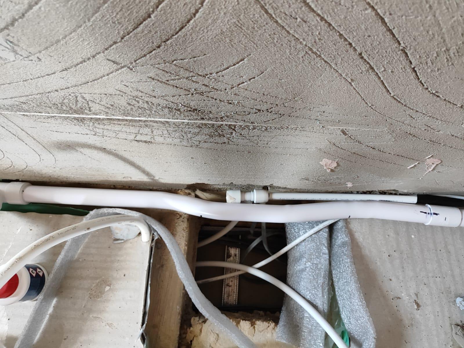
Here's how it ended up I snaked it round some Hep2O so four bends in the end. I heated the pipe more locally than I would have liked so I can see it's thinned a fair bit at a couple of the bends. To squeeze the pipe section in it's ended up leaving the pipe quite taut. Hopefully that won't cause one of the joints to fail.
-
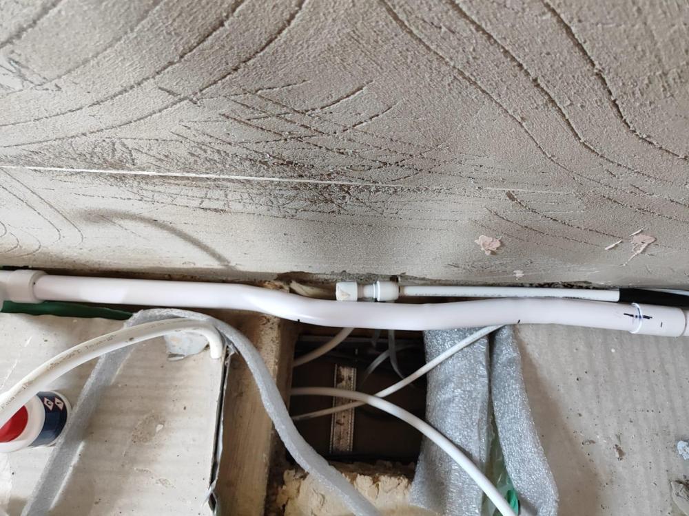
It's nothing special and had to get an angle that shows it clearer. The 32mm pipe on the right is above screed and the 40mm pipe on the left is below screed. To have a consistent drop (18mm / metre) that follows the left hand pipe requires a 24mm vertical offset. There are other places I am likely to need a small offset, so it's not just about this. I hoped someone might say Brand X sell a small S-bend offset part.
-
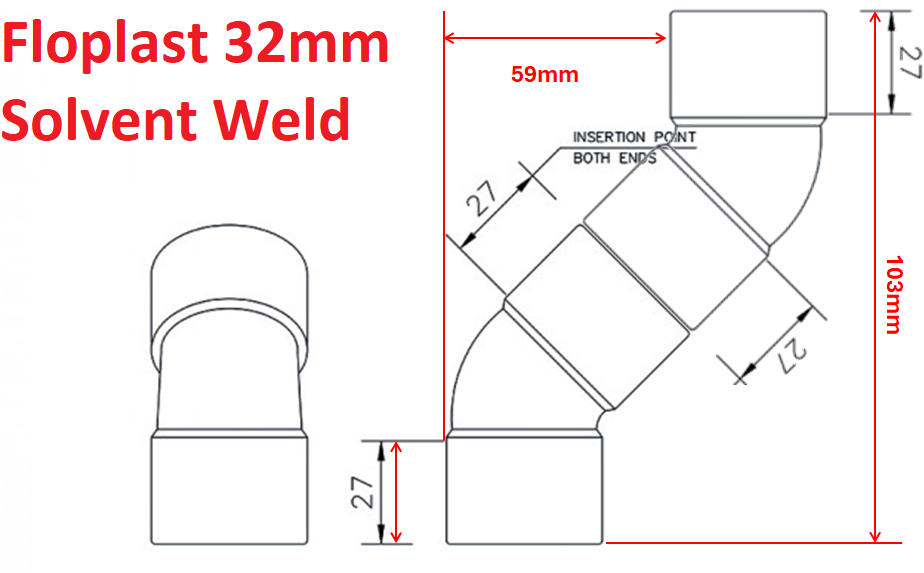
I know I can happily make any offsets I need above 60mm by using two 32mm solvent weld 135° (45°) Bends. But as you can see below, you can't go below 59mm. Are the only two ways to make a smaller offset that 60mm one of these two approaches: heat bend a straight length of abs pipe filled with sand using a heat gun use a length of flexible pipe
-
Sorry if it's a basic question, but I'm aware of two types of reducer and am unclear under which circumstances you use which. https://www.floplast.co.uk/product/level-invert-reducer https://www.floplast.co.uk/product/reducer-3
-
Comfort Height Toilets
MortarThePoint replied to MortarThePoint's topic in Bathrooms, Ensuites & Wetrooms
No basketball players here. I'm 6'2" and the boss is about 5'7". -
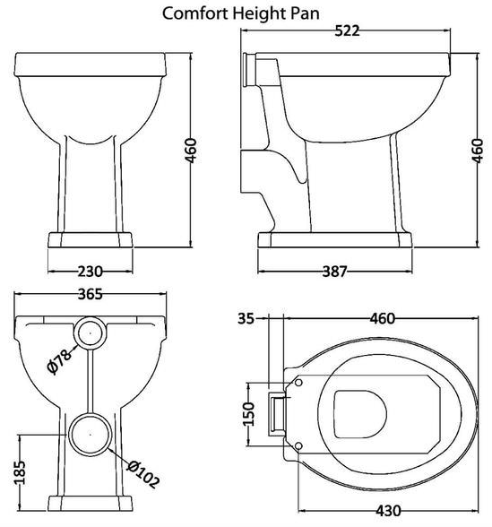
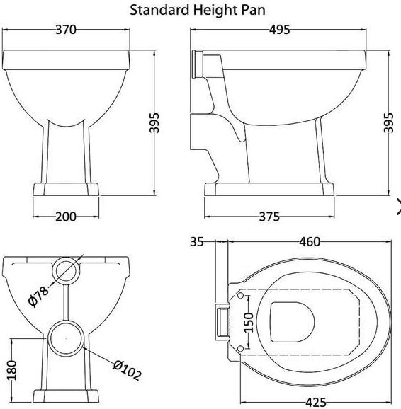
I'm not sure if I have ever used one of these, but I think they are designed for better accessibility. The rim height is higher (e.g. 395mm vs 465mm). That's not currently a requirement for us in our en-suite, but is it generally a good idea? They have another advantages vs box outs as the pan's inlet is higher. Below are the two options for the same model. I also notice the Comfort Height Pan is 522mm long vs 495mm standard.
-
AAV location (Durgo, Air Admittance Valve)
MortarThePoint replied to MortarThePoint's topic in Waste & Sewerage
Odds of both toilets being flushed at the same time should be reasonably low, even if I'm cooking Sending it up inside a stud wall is a nice approach, but this is near only blockwork walls. -
How to measure the angle of a patio?
MortarThePoint replied to puntloos's topic in Roofing, Tiling & Slating
I'm a fan of laser levels so you can do this with one too. The laser shines a level plain so, with the laser set up in single position, as you move away from the house you should measure and increasing height between patio and laser beam. -
Wow these sorts of thoughts can lead you to strange places. Looking at BS EN 12380 : 2002, the flow rate quoted by manufacturers is at a pressure drop of 250Pa. Also the valve must be open by 150Pa and have a measurable flow. 250Pa = 25mmH20 = 1inH20. Most 82mm AAVs have a flow rate of ~40L/s according to BS EN 12380 : 2002. Using this duct calculator, 40L/s creates a pressure drop of 137Pa/m of 50mm ID pipe (only 18Pa/m for 82mm OD = 75mm ID pipe). I hoped the pressure drop would be much much less than that across the AAV itself, but it isn't. Hmm. It is worth noting though that the resistance of two 50mm pipes across 2m is the same as one 50mm pipe across 1m. I have seen some say that running two 50mm pipes to AAV is OK. I could get away with a section of 50mm ID pipe only about 0.4m long before swapping to 82mm pipe.
-
@Nickfromwales and others have kindly pointed out on thread(s) the minimum size requirements for AAV on 110mm stacks, which to summarise I understand as 1no. 3" vent or 2no. 2" vents. However, what about the pipe size leading to the AAV? Can you have a 50mm pipe which steps up to 82mm where the AAV is? The area of a 50mm pipe is about 2,000mm2 and an 82mm valve would have to have a stroke of 7.6mm to open up an equal size area [1]. How big is the stroke on these AAVs? If less, should be OK to use 50mm pipe. In theory 😃. Am I on to something? [1] That area would in the form of a slot be more restrictive than a round opening by a good amount, but let's ignore that as the pipe has length.