
Great_scot_selfbuild
-
Posts
375 -
Joined
-
Last visited
Everything posted by Great_scot_selfbuild
-
Yes (mentioned in first post) - there's a drain, but it will be plugged to retain the airtightness. Valid point about any connection could spring a leak, but only one room has a tank ready-filled with 300L. Good to hear I'm over-thinking it, but a sodden ground floor with timber walls was my worry.
-
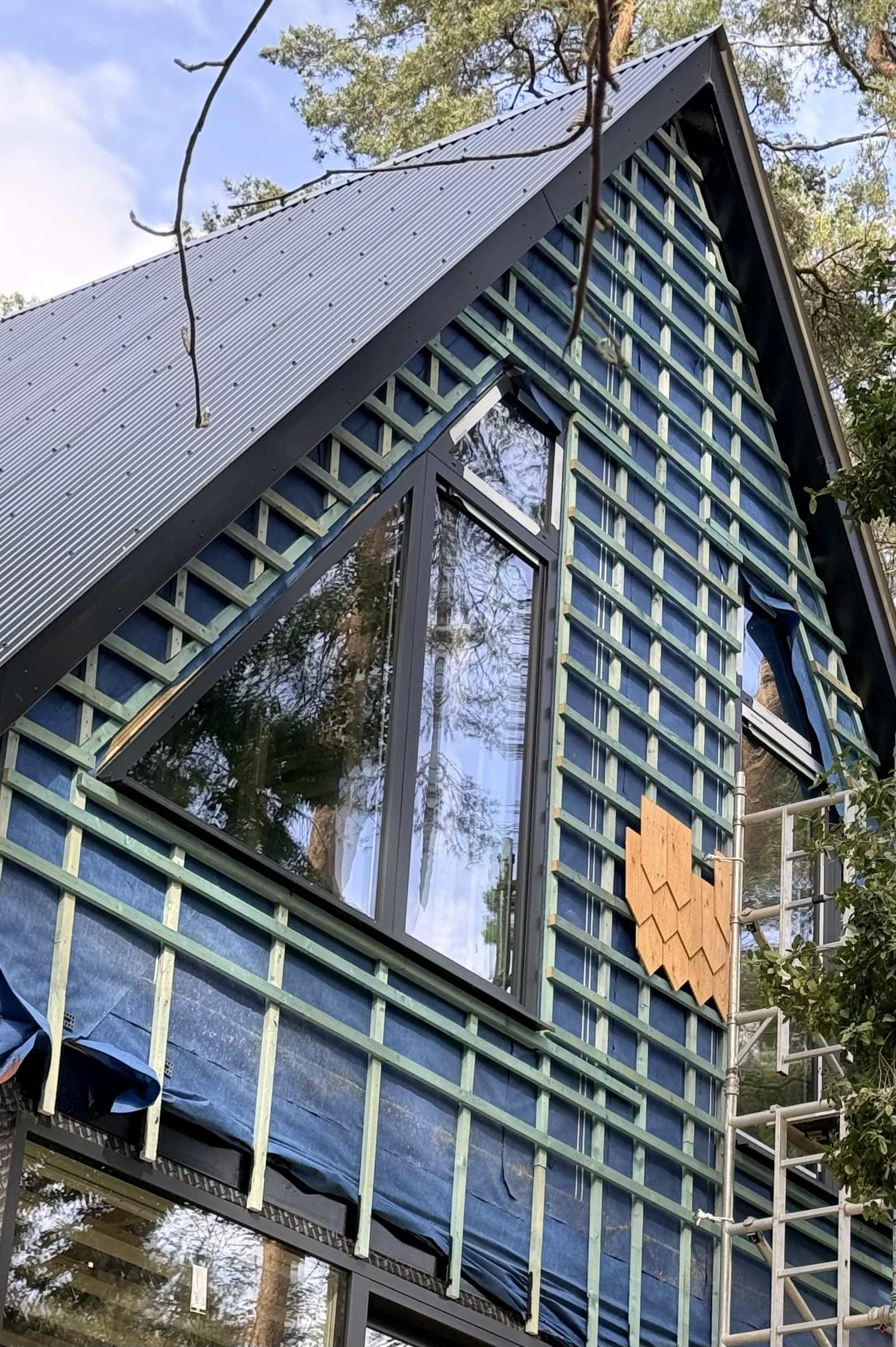
Question for those who have installed (or had installed) timber cladding… I know we need an airflow behind the cladding, and because we need to fit our shingles onto horizontal battens, we have vertical battens followed by counter-battens. I’ve 2 questions: How large does the gap at the bottom and top need to be? What have you used for the insect mesh at the bottom and top? Does it matter if the top and bottom of windows doesn’t have a gap? Around the windows, our builder has installed double-thickness battens, which is good for the fire stopping, but limits airflow - however, because we have counter-battens, there is still airflow laterally and the windows don’t cover the full wall, so does this still meet the requirement?

-
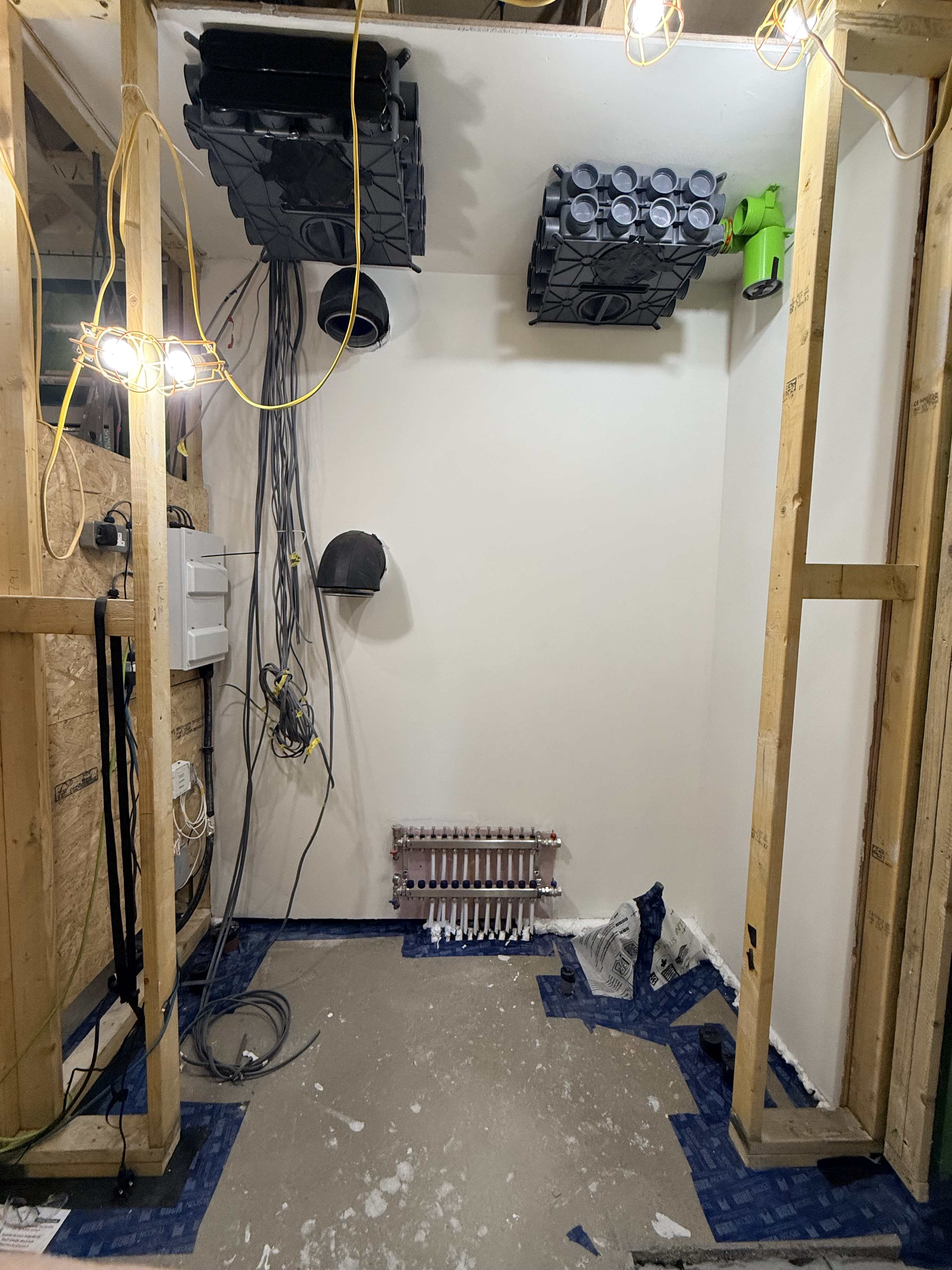
We've a very airtight build (timber frame) and the plant room has a dry screed floor. I want to tank the plant room so the if the DHW cylinder leaked / flooded, then the plant room could hold the 300 L long enough for me to pull the plug out of the drain (before laying the floor I installed a pipe that it could drain through); the floor of the house is suspended off the ground, so there's no issue with where the water then drains to btw. The photo shows the plant room floor with the various ducting and airtight tape. I need the tanking area to be 150mm deep to hold 300L, and was going to batten off the bottom of the door area to create a step-over into the plant room. What would you recommend for tanking the plant room floor and up the sides of the walls to the 150mm height? Any other comments / advice welcome (is this overkill? I'm perhaps being over-precautious about having a timber framed house and not wanting to risk anything significant). TIA

-
Outside tap fitting
Great_scot_selfbuild replied to Great_scot_selfbuild's topic in General Plumbing
Thanks all - really appreciate the advice. BH win again! -
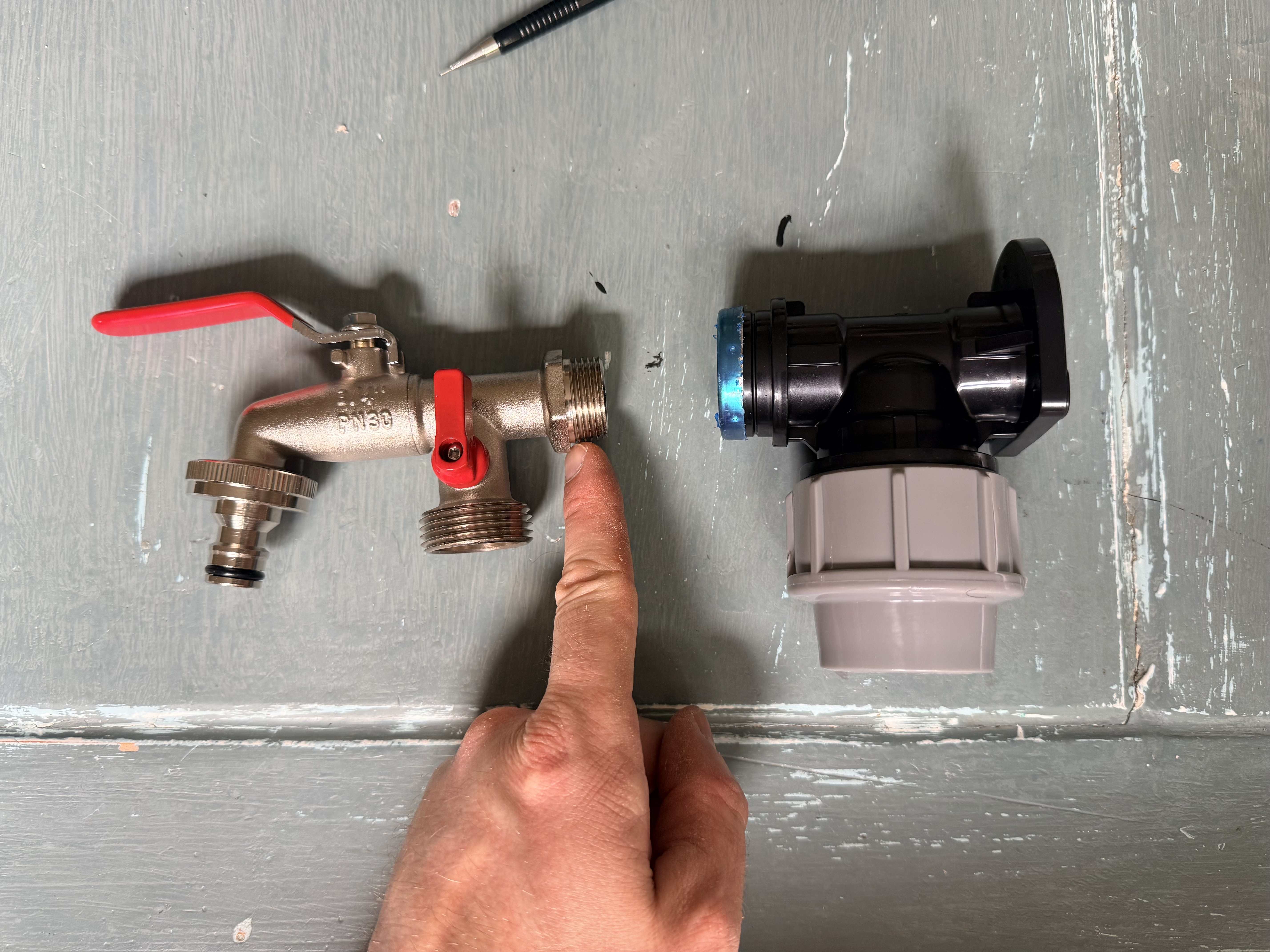
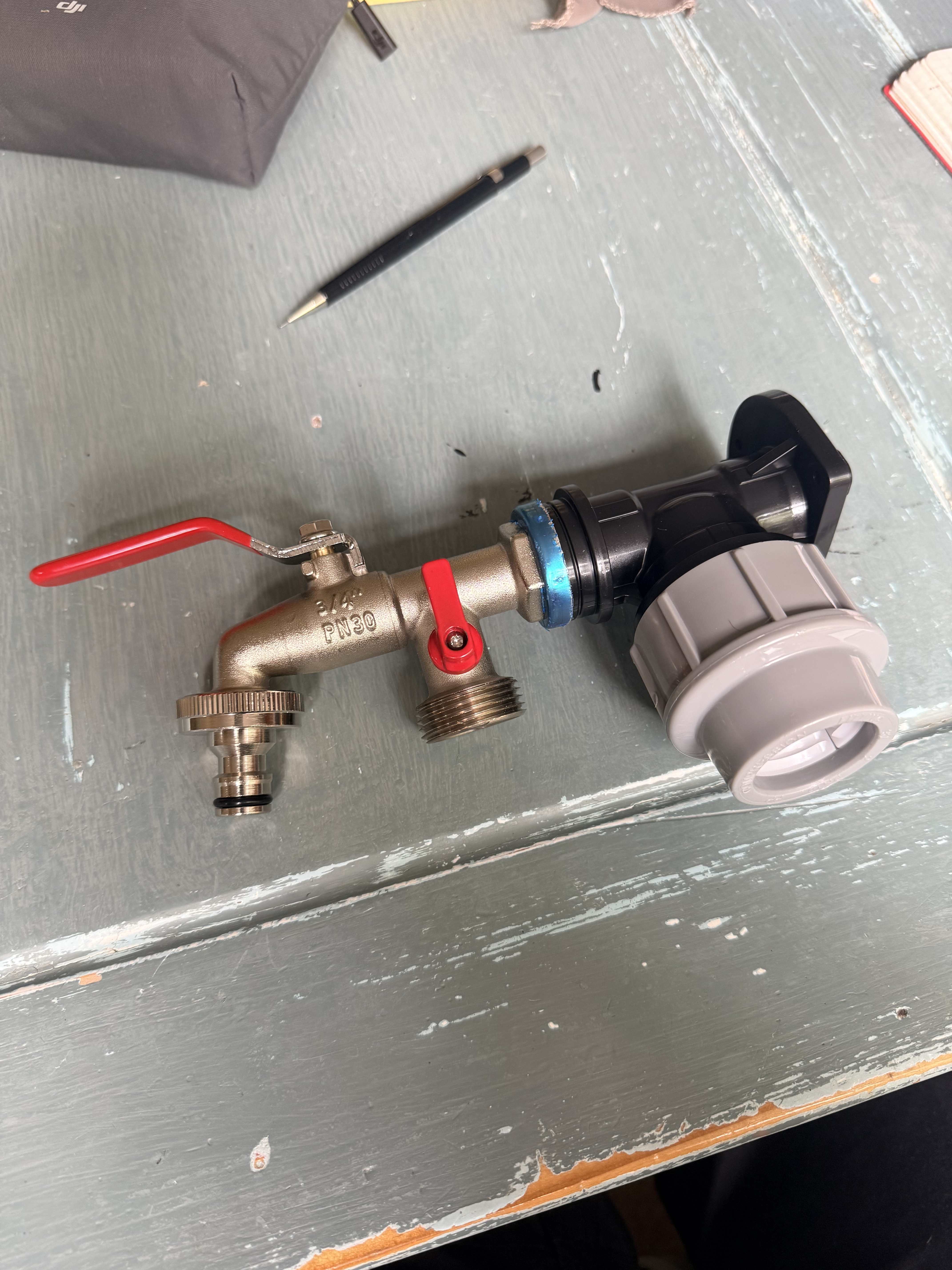
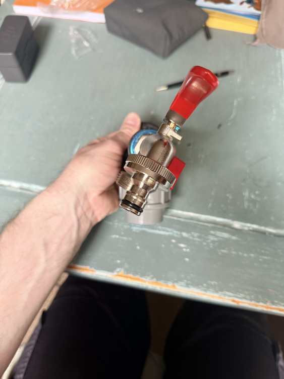
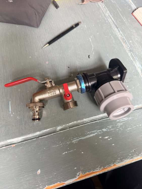
Basic question - should there be a rubber washer / seal on this connection on the tap to the HDPE connection (would have thought it would be supplied). Thread dia is 25mm and as the photo shows, even when just nipped up, it’s off centre.

-
No, but choosing which battles to fight is a skill. Everything about self-build is a marathon rather than a sprint I'm finding. In the scheme of things, this is a small issue tbh. There are plenty of other aspects that wind me up far more!
-
@Spinny good luck - you deserve some after dealing with all that 💪
-
Hmmm... I'm looking to re-use the wood rather than the nails though 🤣
-
Easy to say, less easy to implement, especially if I want to maintain a working relationship for the other bit that I can't do myself.
-
Have considered this, and even did the maths to work out the most efficient spacing, but it's all a compromise somewhere. That will incur cost as well as time (not just the install time, but it means the exact height of the shingle fixing will vary from row to row, so the measuring and checking each time has a greater likelihood of being messed up.
-
The horizontal battens have been installed for our shingle cladding at the wrong spacing. After much soul-searching, I am seriously looking at removing, de-nailing (if that’s a word), and then re-fitting at the correct spacing. Grateful for any tips.
-
By coincidence I came across this too, and then found this useful (clear) YouTube channel which explained how the 2.5mm ring came about from a post-war think tank assessment of how large scale housing could be done whilst limiting the amount of copper needed (well I found it interesting…). This video explained the ring vs radial importance:
-
1 or 2 mvhr units?
Great_scot_selfbuild replied to lizzieuk1's topic in Mechanical Ventilation with Heat Recovery (MVHR)
@lizzieuk1 I’ve had a great service from Pete at CVC systems with a big discount on my brink system (design & supply only). Huge price difference to the response I had from PaulHeatRecovery. https://cvcsystems.co.uk good luck! -
probably end up being about 30-40mm. Foundation is a suspended beam & block floor, DPM, 150mm PIR, Vapour membrane, UFH, slip membrane.
-
@torre The vapour membrane is below the pipes, the slip membrane on top.
-
We’re covering a small area of UFH (which was too shallow to lay the dry screed) with self levelling compound. In searching about SLC I’ve seen mention of a primer - is this always needed? The SLC will be onto a slip membrane which is over the pipes. This is the stuff I’ve been recommended to use.

-
Yes - this is what I’ve had proposed, but I’m taking it on myself now that I’ve accelerated up a steep learning curve!
-
@FarmerN sorry - what do you mean by ‘half run’?
-
@crispy_wafer thanks - we do like some of the more doable DIY and are in need of controlling the budget, so doing this is very much worth our time! I also think I am more focussed on tidy routing of services…
-
This feels a bit high - what’s the opinion here? Just before receiving this, I’ve been looking at running the pipework from plant room to the end points, then this came in (I’m now definitely considering running the pipework myself). Approximate scope: First fix plumbing pipework install. Only installing a mains connection point in the plant room (leaving the UFH / DHW / ASHP to others). 260sqm, 4 bed house with kitchen sink, dishwasher, freezer with water/ice dispenser, downstairs WC, washing machine, family bathroom & 2 en-suite. Doesn’t include bathroom installation (just pipes to the correct positions in the wall). Labour cost £2,750.00 for all pipe installation (not bathroom install) Materials cost £1,780.00 For all materials as above based on 28mm copper main to plank room plus fittings and stop cocks plus 22mm hep2o pipe and fittings for the hot and cold runs with 15mm hep 20 and 15mm copper spurs. Also, isolation valves to toilets, sinks, bath and showers. Thoughts? Experience elsewhere?
-
We’re approaching the point of having the plumbing first fix done and I’m not getting the confident feeling from our plumber - they’re asking for the design of the plant room and system configuration. It seems they are skilled as the practical work when told what to do, but now I’m looking into what a design should look like. I’m not expecting our principal designer to provide a design of the plumbing pipework, and although I’m looking at alternative plumbers, I now want to see some examples of what to expect as to a design / configuration of the plumbing pipework. If it’s not that complicated (which I don’t believe our system is) then in order to get a neat and tidy install that we’re after, I’m wanting to work out a design even if it’s just a means of me assessing whether the plumber we contract proposes something similar or miles off. Help me educate myself - TIA
-
@garrymartin Out of interest, how is this calculated? In terms of ‘enclosed in insulation’, I’ve just been thinking this over, how enclosed is enclosed (if this makes sense). Our situation: There will be 75mm batt insulation in the 89mm stud walls (3m high), then cables running above the insulation in the ceiling space (425mm deep posi joists, with 100mm acoustic insulation), and then out into the plant room.
-
Mandated in our planning conditions - seems to be a default on all planning approvals from our council (not sure if wider as they all seem to vary so much).
-
Couldn’t agree more. I’ve yet to find an element of this project where doing some due diligence and checking of my own hasn’t thrown up very valuable questions or even identified glaring errors. I equate it to doing a QA ‘dip check’ and then finding I quickly need to ramp up to a 100% check 😭
-
Part of the challenge - we haven't decided yet, but equally this could change in the future anyway, so I'm just looking to install the wiring to be the most robust / good design we can. If it future-proofed the design I'd even go for 10mm, but if this is HUGE overkill and only really needed for industrial systems, then I don't want to waste the money. Based on me searches, I'm inclined to run separate 6mm radials. I assume a double oven is one (not two) cable, and a warming drawer is another(?)