


TerryE
-
Posts
3822 -
Joined
-
Last visited
-
Days Won
30
Everything posted by TerryE
-
These are a feature not an issue. Sorry. Excess rain. typically in winter, has to go somewhere, and where it goes depends on your subsoil profile, e.g. a high chalk content will be free draining; a clay layer will tend to keep water near the surface. Without adequate drainage the upper lawn area could saturate and become fluid, leading to your retention walls collapsing. The water coming out of the drains simply means that they are doing their job. You need to get the water away before it floods the patio. Once on the patio where it gathers depends on the fall-away design. Having truly level patios is a mistake. They should really have a few % gradient to allow drainage We have a similar raised area with wall retention, but I put in a soak-away for the upper area linked to our main soak-away, so I didn't need extra in-wall drainage. Where our patio meets the house, I have a 75×75 drainage gutter filled with 5mm pea shingle and linked to the rainwater down-pipe traps. We have one small area where the gradients run counter leading to rainwater pooling, but because our patio was laid on 50mm MOT 1 over 300mm MOT3 drainage that is again linked to main soak-away, it was again simple to use a 110mm circular cutter to cut a hole in the patio at the low point, dig out the sand and MOT1, them insert a but of 110mm downpipe as a sub-layer retainer with a slot in cover to create an instant drain point. You and your builder need to discuss similar remediation if you find the pooling runoff unacceptable, but also realise that the builder won;t regard this as a free-remediation, so you will need to do this work yourself or pay to have it done.
-
+1. I have a 0.5 ACH airtight house, so I can't add through-wall plumbing willy-nilly. My outside tap is currently fed from a spur off the riser inside out house, and back into another duct under the slab's ring-beam, then under the patio to a wall-mounted riser. These flush mounts are really only suitable for new taps where you are plumbing from a utility out through an adjacent external wall. I also use the outside tap once every couple of days, so it needs to be readily accessible.
-
Even though my outside tap riser is pretty-well lagged, this thread has reminded me that I should a nice very lagged booty covering the tap itself. Thanks @Pocster
-
Just don't forget to check if you do have a long cold snap as letting this freeze and backup will be a total PITA.
-
This a good idea if you want to guarantee that it doesn't freeze. if you lag down to G/L and use a small soak-away as @Kelvin and I suggest then you probably would only need to turn it on for the few days over winter when there is a sustained hard frost. We don't have this prob since we vent ours internally into the foulwater stack system using a McAlpine In-Line Vertical NRV (these are designed to allow these and similar overflows to be fed back into the FW system). The nearest we have is that we feed all of our potable water through a Harvey water softener. This is great for cooking and brewed drinks, but we prefer taste of the unsoftened mains for drinking as plain or fizzed water. I have a garden tap by the back door that taps directly off the riser before the Harvey, so once every day or so I take a big jug outside to refill all of our glass water bottles that we keep in the fridge from the outside tap. This is a tiny hassle and far less than that of adding an extra unsoftened water tap inside. This outside tap is similarly lagged and does freeze up a few days a year on average. When this happens, I just take a kettle outside and defrost it if our need to refill is getting desperate. Not really workable option for an overflow.
-
These sorts of trickle overflow are often turned down into a small stone chip or fine gravel soak-away at ground level, maybe the size of a plant-pot or bucket. The pipe should be insulated to ground-level. I am not sure where you live in the UK, but the ground very rarely freeze much more than the top few cm where I live in Northants even in the worst cold snaps, so this approach takes the water away without leaving puddling with can freeze and cause a slip hazard.
-
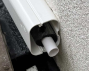
This outlet design will cause probs, IMO. The horizontal run will cause standing water which will start to freeze from the drip, building up and then block. Perhaps a case of aesthetics over fitness. 🫢
-
Janet simply hated them for their flaws, but I was torn: I really liked the concept but there are so many design issues left unaddressed or unoptimised that I am glad that we decided to replace ours. Take the issue of the strict cuboid form factor. Superficially this has lots of installation advantages because you can install the unit in a tight space without much space overhead -- except this is a dangerous assumption unless all of the risks are addressed. For this concept to work you would really need a unit designed for all maintenance access on one side, and this is not the case. All components that don't have a life that is significantly greater than that of the overall unit could fail in life and therefore need to be field-replaceable, e.g. heat sensors, heating elements, etc. The fluid design issues can't be ignored but IMO they largely are. The Sodium acetate trihydrate (SAT) PCM is heavy (S.G ~ 1.45) and cycles through a phase change roughly daily. The PC expansion coefficient is small but not zero, so the unit must be designed to facilitate this flex, and ditto all connectors and fitted components. A strict cube is a bad choice there. The cylinder is preferred for a reason. The fascinating Youtube History of the Jerrican discusses the evolution / design of a similar cuboid container that has been largely unchanged in 70 years. The SAs use plastic cells in a bolted steel box for support, but if you remove a side panel for maintenance access (except when the unit is completely cold) then game over. Ditto heat transfer. The unit needs to support ~30kW thermal transfer from the PCM to the potable water and this requires internal cell design especially as this has to happen throughout the phase change cycle. The SAs do better here, but IMO the UniQ implementation is still far from optimum. I could go on with more detail, but this post has already lost most readers so time to pause.
-
As you may have gathered from this thread, SunAmp units are far from maintenance free, and so IMO they need decent maintenance access all round, compression turn valves on all in/outs and the ability to slide the unit out in extremis. We made the mistake of not doing this. They are also extremely heavy. So my suggestion is that if you do want to "hide" the unit in a "wardrobe" then install it on a platform and make your "wardrobe" open backed and fixed to the wall with bolt fittings so you can unbolt and temporarily remove the wardrobe entirely for easy maintenance access when needed.
-
If you can't get a decent consistent finish then you might need to paper the ceiling with lining paper to get a decent uniform base for painting.
-
What happened to your idea of anti-PCM bund?
-
Chip off a bit and try to dissolve it. It hardly dissolves in cold water but you can get it to dissolve in boiling. TBH, I suspect that even with mechanical removal / steam cleaner, it'll be hard to get back to a decent decoration surface. From the OP, it looks like you've got the edges of 4 or 5 8×4 PB sheets compromised that wont take decoration, so there is quite a lot to take down / replace. One alternative to stripping out the entire ceiling might be to sand down then put up a second PB layer on top.. @Nickfromwales, if this is isn't giving recurring nightmares, you might have some remediation suggestions.
-
@MikeSharp01, this is an artefact of SAP rather than a real issue. Last night we used 2.3 kWh heating our after back to target. We've got a bit of a Dunkelflaute at the moment so the cheapest was 18.2p so or H/W cost about 42p. SAP needs fixed not the implementation.
-
I assumed that the PCM salt would be soluble in water. I found this not to be the case once the salt had changed into the solid crystal phase.
-
Glad to have been a help. As I mentioned out kitchen is essentially arranged in a U around a 2×2m walking area with a peninsula walnut work-surface acting as a divider between this and the dining table / area. We have full-length storage on one wall of the dining area for low-access items and storage. Hence 95% of our kitchen work is only a step or two away from the sink or induction hob. When I need to access the full-length storage, I do notice the extra 10+ paces that I have to take to get there and back. It's easy to make up a temporary table / island from a couple of cheap internal doors and DIY trestles made from 22×44 PSE timber, all for under £200 I made some up for Jan over 10 years ago. I used them for an ad-hoc working surface during our build and still get them out or our storage room, and put them up a few times a year to do jobs on. In terms of your pics, my Q to you is: do you see yourself spending your time? Cooking in important but I doubt that few spend more than 10 hours a week doing so. Also what you need to do here is to focus on how to make this time efficient and least tiring, so positioning and placement is a key design driver. If you are going to spend more quality time relaxing in the sitting area then surely you should constrain your options here and focus on the correct balance between relaxing and preparing food.
-
@Jeremy Harris, really nice to hear from you again. Please keep in contact. You've been missed. You seemed to pretty much to have removed your Internet footprint, especially with the lapsing of the mayfly domain. I once did have a search and I found an email contact some in some other context, but decided not use it in the end, since I figured that this would be intruding on your privacy. Anyway back to SunAmps. As Mike said, in the end I gave up on them, and have posted on this journey on several topics. In terms of replacement, I went for a decent OSO 250L UVC (immersion only). This has a cylindrical vacuum panel jacket similar to that used in the SumAmps. The daily parasitic heal loss is somewhere between 1-1½ kWh; this only about 30% more than my 2 SunAmp PVs. Not enough to cause overheating, and this does ultimately heat the house at a CoP of 1 anyway. I have top and bottom digital thermos and once a day my control system uses their readings to estimate the top-up heat required to bring the UVC back up to temperature. I then schedule heating for least-cost on my Octopus Agile tariff so most days the cost of H/W is around 20-50 p, and often less. This all works well, and we've never regretted the switch. Now lessons from the tear-down of the defunct SunAmps: 10/10 for the concept; 2/10 for controller board design and implementation; 5/10 for the mechanical implementation, but overall I don't think they were engineered for a 10 =-year life let alone something longer. The form factor also encourages supplier lock-in. They were still using the same controller board until recently for the UNIQ series. They were really terribly electrically, thermally, etc. Just nowhere near what I'd expect on a product at this price. I was replacing one every 2-3 years. I can go into more details if you want. I had one of the thermometers fail as well In terms of plumbing construction, the PVs were a nightmare, in that they were practically unmaintainable in-situ. When I did the tear-down, just too many joints were weeping and showing bad corrosion. Clearly there was steady dripping into the internals in one unit. This might have been addressed in the Uniq units. However note that @Nickfromwales and others that reported issues with the internal cell immersion heaters for the electrical boost option: these aren't a replaceable component. The only practical option is a complete cell swap and this isn't a field-repair option either. One of the 4 PC cells showed evidence of internal corrosion on the internal copper at a solder joint. If this went then this would have let the potable water bleed into the salt chamber and ultimately caused the sort of failure that you experienced. So IMO, if you do do a SunAmp swap then you should anticipate a similar life of under 10 years for the replacement unit.
-
TBH the internals should be dry and well drained, so personally I'd just do it in timber, e.g a length to wood decking or other preserved wood from Wickes or equiv. You cam pick up a length of 25×120 mm decking for about £8 and cut to form a U profile cover with a nice sloping lid. Easy to fix to the wall. Maybe not the most beautiful, but it will do the job and stop your drain blocking. And yes, in 10 years time you might need to replace it. 😅
-
Once insulation gets (even slightly) wet then the U-value collapses. I would route the pipe vertically, and box it in with a mineral packing in between the pipe and the boxing.
-
Good catch. If you have an imaging camera like yours, then you really should have a systematic explore around house, especially around all fenestration edges and corners, so you know where you bridges and air leaks are. Fixing them can often be simple and cheap -- just tedious; this can save a lot on your heating bills as well as addressing mould and damp issues. Don't forget to wrap up and do the same from the outside looking at the fabric. This will sometimes catch thermal leaks / bridges that aren't too visible from the interior check.
-
I'd have to dig through 10 year-old files for this sorry. Our plant area all fits in a 80 × 150 cm cupboard that is along one side of our downstairs loo. The UFH pipes and the two pipes come up into this. I use the 110 mm foul-water push fit OSMA pipe for these -- the same as my FW runs running under the slab in the crushed MOT 3 layers. (You need slow bends to turn up into the slab to make it easier to pull wiring and pipes through them.) As far as the MBC crew was concerned these were just prepped and laid the same as the two FW runs that lead to my 2 internal FW risers.
-
IMO Islands can be effective but they can also prove a disaster in practice and in living. The problem is that if you both decide after a few months living with that you've made a mistake then the remedial costs and disruption make it impractical to do anything to fix the issue. The advantage of something like a more traditional table is that you can move it and replaced it with a different one -- you can also start with a cheap IKEA or the like one and live with it a bit before making your final choice. Sure you might end up buying a £200 table and later chuck it out or repurpose it elsewhere, but that is going to prove a lot more cost- effective than £10+K remodelling work 2 years in. The kitchen area should be a focus for cooking and food preparation: the cookers, sink, fridge freezer, and main work surfaces should be 1 step (2 at most) from the work focus. Any more and you will spend your time walking around and not working. For example in your layouts, it's about 10-12 paces from the inside of the pantry to the microwave /cooker and 5 paces from the sink You comfort sitting area and positioning of the 2 two-seater is constrained by the fixed centre island. You mention children. What about grandparents and friend visiting? Where is everyone going to sit? What if you decide after living in this space that you'd rather have an extra 2-seater or be able to pull and extra chair or bean bags into the area for everyone to sit around together. You can't practically. The only option you have is for everyone to sit around the dining table. So in my view none of your options are that good. It seems that you've gone to a kitchen supplier and got one of their designers to lay out some design options. They make their money on selling units, not making a liveable and working kitchen. 90% of the time 1 person will be doing the prep and cooking, and most two. Start by deciding where the main user will want to stand most of their time, then the sink, cooker, fridge, main cupboards, main prep surface need to be at most one pace away with the least frequently accessed devices, units 2 paces away. Below surface storage can be a pain. We've our most commonly accessed stuff at waste level or eye level, and use swing out or pull our storage / trays for all our commonly accessed below-surface storage. You can guess that I am not a fan of islands. I wonder how many here love their islands and would never live without one. We do have peninsular walnut work surface acting as a divider between our main kitchen / prep area and our dining area complete with bar stool-type seats around it, but to be honest it doesn't get used that much -- in practice it's more of an over-spill surface and a zone divider.
-
WhiteWing 16 channel DMX relay
TerryE replied to Thorfun's topic in Networks, AV, Security & Automation
There are lots of ESP32 based relay boards available on AliExpress at all sorts of relay combos. The build quality and electrical design of the better named suppliers is excellent. The advantage of going the ESP route is that you can load these OTA with ESPHome or Tasmota firmware which makes them v, easy to integrate to Home Assistant, etc. You need to be very aware of the contact life, especially without snubber protection (or flyback diodes if switching DC). I chain mine to contactors if I am driving anything about 1A, but this definitely requires snubber/flyback protection for the control relays. -
Another happy MBC owner here. We put some extra 11 cm pipe runs down from the plant cupboard under the slab and out beyond the peripheral path . We ran various services through these using various flex sleeving covers. These proved great during initial build, but were flawed for future additions -- basically after 2 years of external ground-works and landscaping the external covered pipe end got lost / buried too deep / covered by paving etc. We had a rule that no trades were allowed to breach the twin-wall, so we did all the through ducts / conduits then once the sparky etc had done using them we foam filled and silicon-sealed them all before the pressure test. I only wish we'd put some extra through pipes "just in case" as well. There are no air leaks and tiny U-value hits doing this to it;s a damn site easier drilling one of these out if you need to add extra services later than trying to add a new airtight through duct once the building has been boarded out and plastered / outer skin complete. I ran power and Gb enet to a small shed close the house and added a PoE switch here so that all of the external cameras etc. could be cabled to this shed.
-
It doesn't have to be a door of course. Depending on the diameter of your fan, it might be easier to fit one to an opened window light.
-
You need to be careful that you don't do an apples and oranges comparison. MBC contractually guarantee passive class performance, so in our case (and others on this forum who have used them) all three MBC crews spent their time doing such builds, so they really understood the fine details of making it happen. We got 0.5 ACH on first attempt without any trouble shooting of missed leaks. Tightening some of the loose Internorm window adjustments to spec dropped this by another 30% or so. @SBMS point is very valid if the contractors teams have a similar understanding and attention to build detail. It is more difficult to avoid air leaks and bridging in a B&B build compared to the MBC twin-wall technique which avoids most of these by design.

