marshian
-
Posts
1590 -
Joined
-
Last visited
-
Days Won
6
Everything posted by marshian
-

Can the flow temperature be too low?
marshian replied to JohnnyB's topic in Air Source Heat Pumps (ASHP)
That’s not a huge circuit IMO On the bypass valve (my system is boiler rather than HP) but I have it set to only open when the circuit pressure is driven up to the point where just 1 rad is in circuit (from memory that’s about 0.3 bar on the scale) and that stops me dead heading the pump and keeps the flow rate up enough for the boiler to fire once flow temp has dropped enough -
All of the above Viessmann 100 W heat only (16 kW) Not a single rad remains from the original house set up 95% of the rads were changed a couple of years ago when I was running a 24kW glow worm boiler the point I was is that rads correctly sized for flow temps and room demand will work perfectly well whatever the heat source is
-
I don’t get the heat pump and rads comments I could run a heat pump instead of a boiler with the same flow temps I’m running a gas boiler 13 rads with a flow temp of 30 - to 40 deg depending on outside temp - it’s an early 1980’s with some insulation improvements (loft insulation is mainly 70mm so sub standard) and I’m running it 24/7 with setbacks at night and during the day when there is no one home - rad delta is around 6 to 9 deg (depending on flow temp) none of the rads are in the traditional sense hot but room temps are comfortable.
-
Hacking combi to run dhw and heating at the same time
marshian replied to sonicboom's topic in Other Heating Systems
Is the output of the boiler capped for HW for either temp or boiler power? I can understand the output being capped for CH because 26kW boiler feeding a 3kWh heat loss is massively oversized but it makes no sense to me to have only 7kW and 40 deg water Have you got the ViCare App so you can see what the boiler is doing? In my app I can set HW temp different to CH (100-W heat only with 115L cylinder and HW demand box) I'm pretty sure the app would enable you to increase the HW set point to say 50 and the boiler would modulate according to HW flow. I really don't see the point of trying to hack the boiler to do both at the same time - with a heat loss of 3kWh you aren't going to see a house temp drop even if you are running a really big and deep bath!!! -
Company I have worked for since early 90’s embraced that same concept - all software central - little boxes instead od desktop PC’s all in the name of effeciency and cost saving on IT It was a bloody car crash and I got to see it implemented and the business suffer the workrate of everyone go down the toilet and the IT dept run around like loons trying to make it work…… 18 mths later pretty much everyone was back to proper desktops or new fangled laptops
-
Is there an option to lift the floor and run that cable underneath?
-
Neighbour’s ‘Temp’ building maybe ignoring building regs.
marshian replied to G and J's topic in Building Regulations
Sounds a lot nicer than a park home…….. -
I'd be starting at the slowest speed possible and seeing how the system responded If the rad circuit has been balanced using the lockshields for a pump set to max you might have to allow a little bit more flow thro the rads but it may not be necessary - I can run my pump on 1 or 2 with no re-balancing required - only difference is the difference between flow and return on each rad drops with an increase in pump speed.
-
I don't read that the same way - sorry I read that as without PWM the pump can be run at one of 4 speeds

-
Why not try turning the pump speed down? I would be surprised in the system needs a pump running flat out unless it's a really big system with a lot of rads and UFH I've got 13 rads no UFH and I have a smaller pump running on min speed (out of 3) - I can run it faster but the temp drop on each rad gets narrower and system noise increases as TRV's start to restrict flows In fact I'd actually try the slowest speed and work up from there if the house room temps started to nose dive (it's currently a good environment to do this exercise) I'd gradually increase pump speeds until control was there
-
Weather Compensation for Radiators only and UFH only
marshian replied to John Carroll's topic in Underfloor Heating
Can I make a couple of comments 1. You make very nice spreadsheets that are really easy to follow and incredibly useful as a resource - thank you 2. I'm very sure all of my rads are oversized 😉 but your spreadsheet has made me actually think about how oversized mine are (I did the heat loss calcs a while back and when I've finished my loft insulation project I'll do the whole thing again to correct for the changes). I will probably help my understanding if I go and work it all out room by room. I'm not about to change rads for even bigger ones - that would probably be an expense for little gain (or a stupidly long payback) I'm already operating the boiler on CH in condensing mode all the time the returns on reducing flow temps further might be fairly damn small. -
Weather Compensation for Radiators only and UFH only
marshian replied to John Carroll's topic in Underfloor Heating
I would think that the WC curve would be the same for UFH as Rads if the heat loss of the property is the same and the heating is running in the same way The rads are just providing the distribution of the energy same as the UFH to replace the heat lost. I'm running my WC at a curve of 1.3 but I'm gas boiler and scheduled heating rather than 24/7 with setbacks - I'm absolutely sure I could run a lower curve (1.0 or 1.1) if I moved away from scheduled heating (I get to do this at Xmas when I'm home for an extended period). UFH is just a massive great radiator in the floor but it's slower to respond and needs a longer lead in than rads at lower flow temp but once it's up to temp it's just replacing the heat loss -
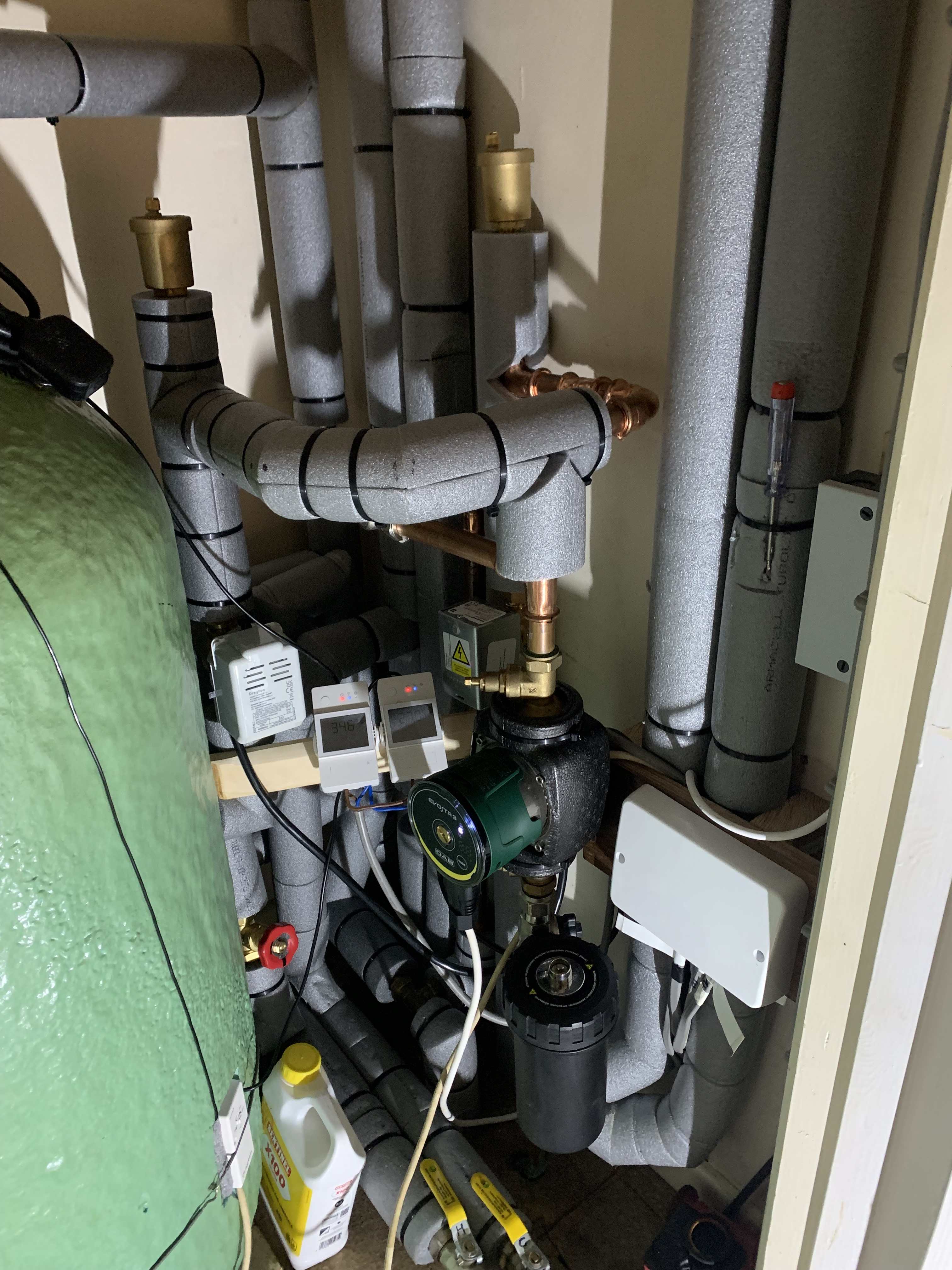
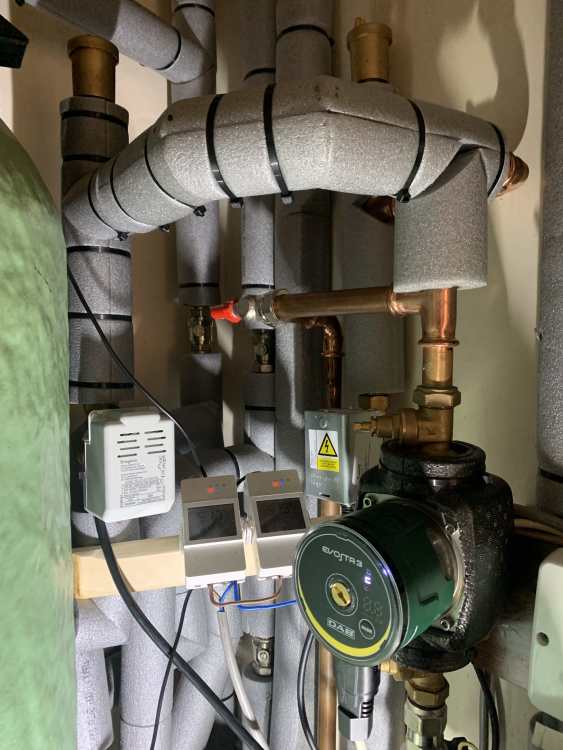
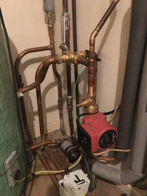
OK running out of time because we are going on holiday for two weeks but I’ll answer what I can Pump speed 1 10-11 W in normal operation Head is 1.8 m flow rate is 0.7 m3/hr on HW and 0.6 m3/hr on CH ( it can get down to 0.3 m3/hr as room TRV’s shut down Boiler flow temp 40 return temp 30 on pump speed 1 Most rads have a 9 to 10 deg drop between flow and return Pump speed 2 15-18 W in Normal operation 3.0 m head Flow rate is 0.8 m3/hr on HW and 0.7 m3/hr on CH (again it can get down to 0.3 m3/hr as rooms TRV’s shut down Boiler flow temp 40 - return temp 34 most rads have a 6 to 7 deg drop between flow and return House has 13 rads 2 ladder towel rails (toilet and utility) 2 med size verticals (Bathrooms) 1 large vertical (kitchen) 4 T22 500 x 1200 (bed rooms) 2 T22 500 x 1400 ( Dining and main hallway) 1 T22 600 x 600 (front hall) 1 T33 700 x 1400 (living room) Re pipe calcs (just saying whilst the height of the vent was as stated the length of the pipework to the vent is probably 7m from where it is below the pump to the outlet above the F&E tank. So there is a fair bit of water in the pipe) Automatic air vents are open all the time but when air is introduced the aerated water tends to stay in the pipes - never hear them expelling air unless it’s a system refill then they hiss away a lot if I shut the bottle vents for a day or so I’ll get a 1 sec hiss when re-opened so I know they work ok - I just think when the circuit gets a slug of air in it they aren’t very effective at getting it out due to flow of water in the circuit I think that’s all of your questions answered Better picture of the pump and pipe configuration below (with all the lagging almost complete it just looks like a sea of grey) I’ve not lagged the bypass leg because I’m still trying to find a good compromise setting that doesn’t allow too much return when all rads call for heat but does allow a little flow when some TRV’s start to close
-
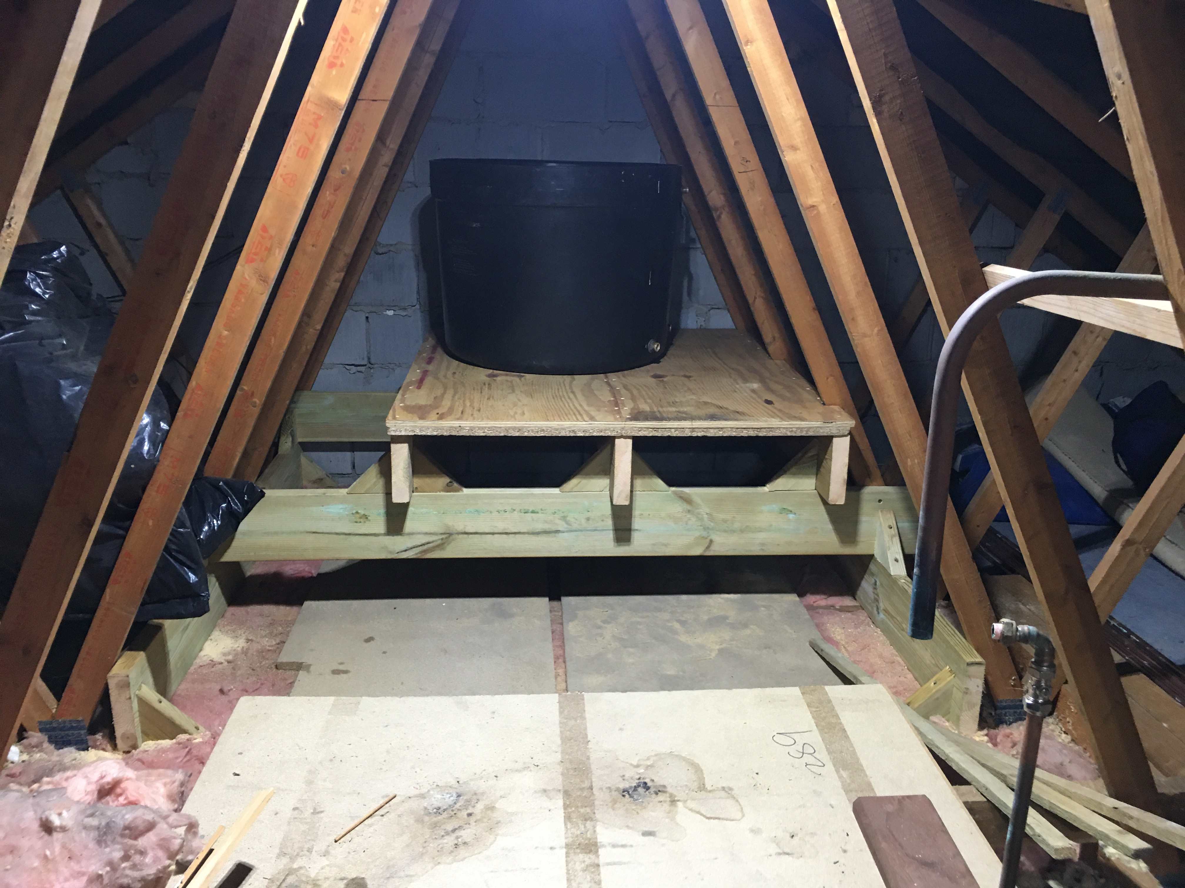
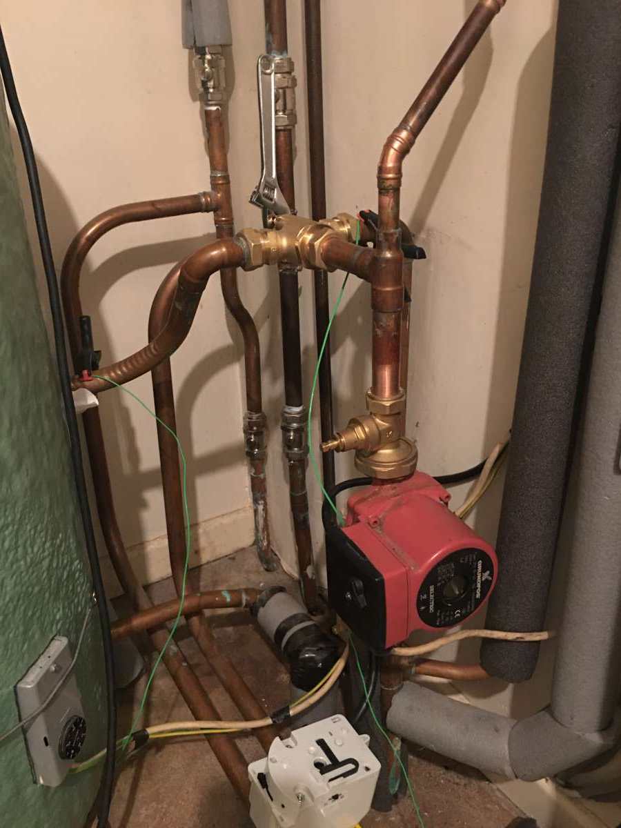
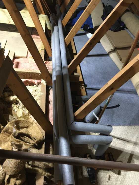
Current set up Filter, pump assembly is all same From pump T to bypass valve to HW return then T splits to go right for CH (NO zone valve) or goes left to HW (NC zone valve) coil in tank Both CH and HW legs have bottle type air bleeds Boiler is 1m below the pump I will try to do the new glass trick today Your calcs on volume of water in 22mm pipe assume that the height of the vent is also the length of the pipe but thats not the case the pipes go thro the ceiling of the airing cupboard and into the loft space - there they travel horizontally 3m along the loft before rising up to the F&E tank. the tanks were relocated a while back because they made access to the loft space difficult


-
I guess this means whatever problem I have it's always been there - I just put something in that masked the issue Now it's set up as X plan and has bottle vents on both HW and CH legs* they aren't as effective removing air as a 1.5 M length of 15mm copper right above the pump *sighs
-
Oh that is such a long story I don't want to go there........... Set up was a Y plan with a 3 position valve HW HW&CH and CH only The whole system was controlled by a sunvic set up and when the 3 postion valve failed I converted to a drayton - however that was incompatible with the wiring centre and so an adjustable spanner was deployed to switch from HW to CH and Nope I'll stop there................. The pipe you want to know where it's going was to a manual vent - I've always had an issue with air in the system since we bought the place in 1991 it used to accumulate over time so I put a stupidly long leg of 15mm copper pipe up the side of the airing cupboard and just used to bleed it every month...................
-
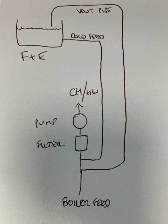
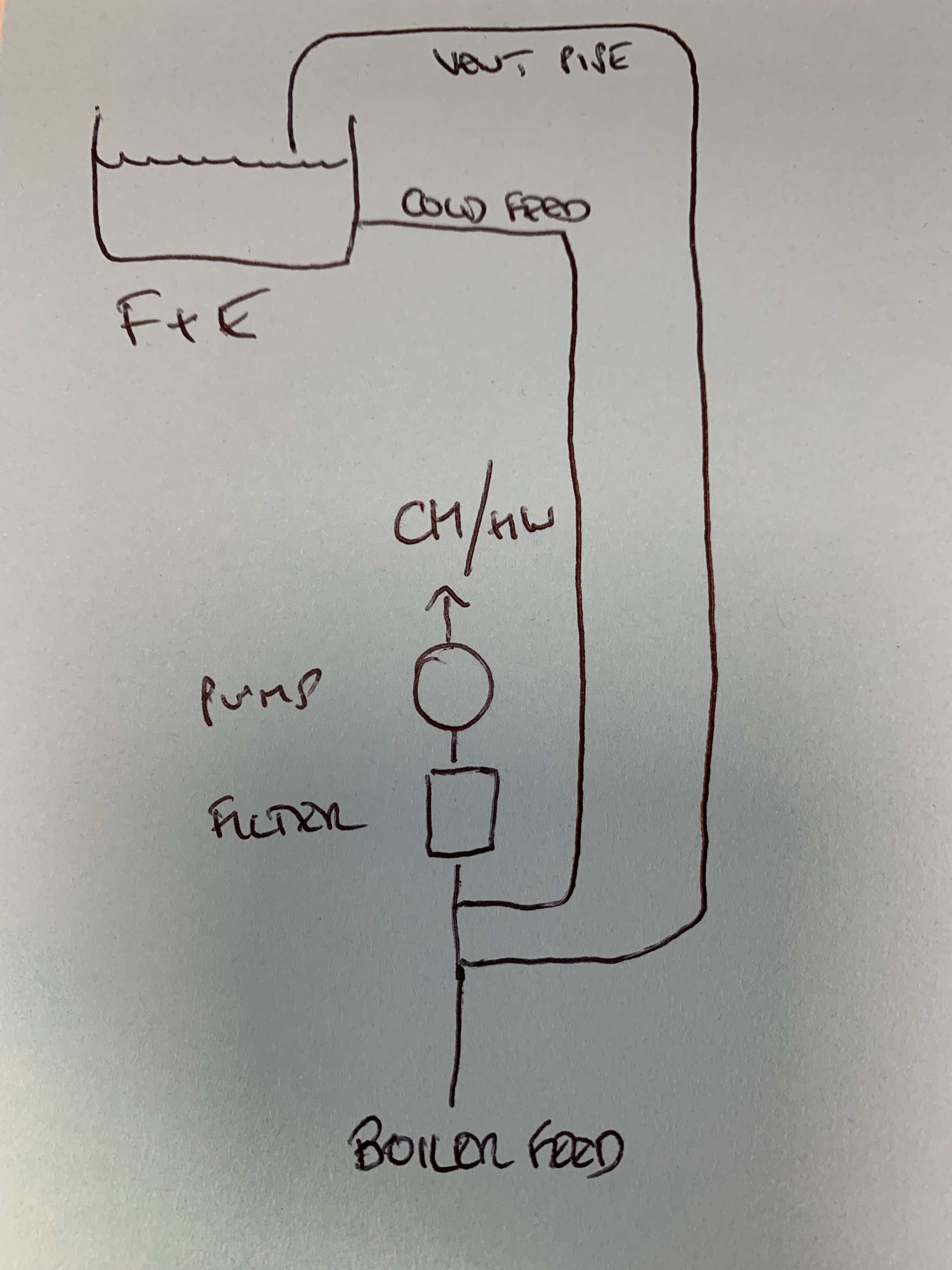
Yes to both The F&E tank is only feeding the CH Circuit - nothing is T'd off it - there is one isolation gate valve in the line but it's fully open The vent for the CH circuit is vented to above the F&E tank There is another vent from the HW cylinder that is vented to above the Cold Water Store Tank but there is no connection to it. The pump is installed the correct way round and as I thought the magnaclean filter has no flow markings and according to the destructions can be installed either way up The distance from the bottom T where the Vent is to the top of the pump gate valve is 58 cm it's as compact as it can be From the pump to bottom of the F&E tank is exactly 3.4 M The vent pipe is at it's highest point before it comes down to just above the surface of the header tank water is another 0.6 M Huge apologies to @Little Clanger for the threadjacking
-
Just looked at the instructions - not sure there is an orientation requirement on the Magnaclean but I will look carefully at the body when I'm home tonight
-
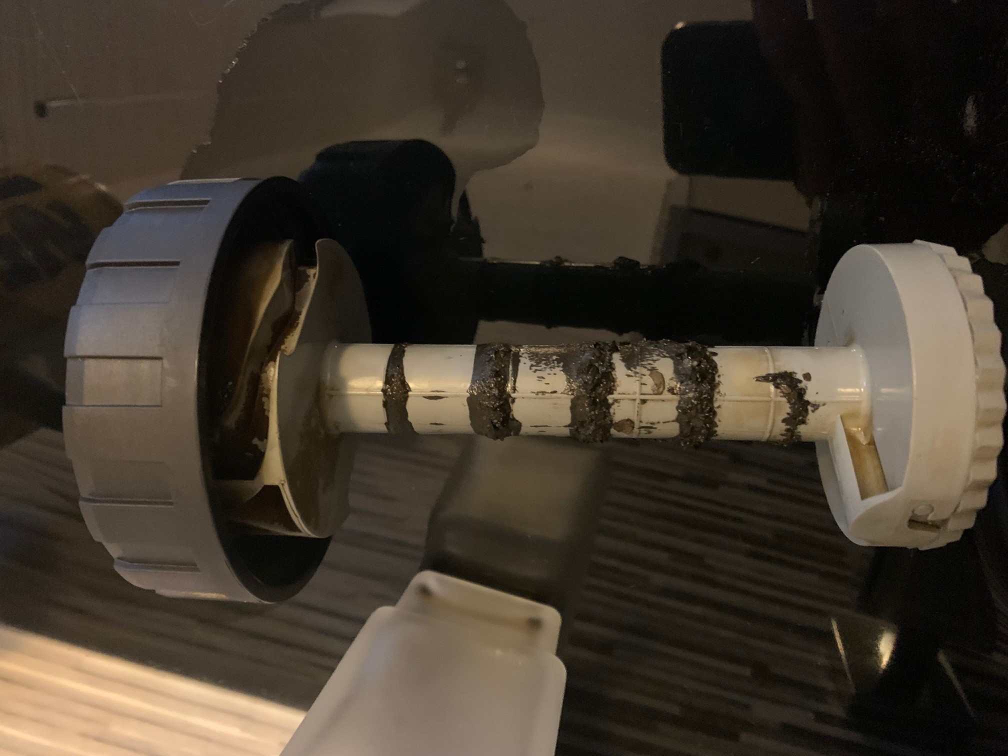
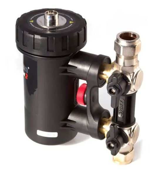
I'm not aware of an arrow in the filter body but I'll check that too Filter is checked every three months and rarely has much on it - below is as bad as it gets

-
Yes exactly that - 99.9% sure the pump body has an arrow pointing up but I'll check again
-
They are effectively stacked (with the absolute min of pipe between all items) Top Zone Valves Pipework Gate Valve Pump (130 mm flange to flange) Gate Valve Magnaclean Unit 22mm T (15mm inlet) Cold Feed 22mm equal T (22mm Vent Pipe) 22mm Flow from Boiler Bottom I can do exact measurements if required but it's all very tightly packaged
-
Ahh so one 22mm pipe feed from F & E to below the pump and then the vent tee's off close to the tank outlet - that would be do-able with existing pipework Attached is picture of set up before recent changes to pump filter configuration and valving
-
Glass of water results (might have to repeat it with a larger glass) pump on - level stable pump off - load of bubbles followed by a level drop pump on - all the water stolen from the glass Just for info when on HW both cold feed and vent pipes below the pump get hot for a few feet up the wall so there is a level of water in them When refilling the system from a drain down it fills fairly quickly so I think the cold feed is clear I would have expected the vent pipe to have water in it to the same level as the F&E tank
-
Yeah I’ll try the glass of water trick the filter is a magnaclean unit
-
Ok see below