


marshian
-
Posts
1590 -
Joined
-
Last visited
-
Days Won
6
Everything posted by marshian
-

Gas Boiler Flow and Return Pipes In Copper?
marshian replied to tuftythesquirrel's topic in Boilers & Hot Water Tanks
Made me chuckle reading that - I'm still getting closer to the advice given by yourself now 5 out of 13 rads/rooms are now running pure weather compensated flow temps with no TRV influence OP - Bearing in mind the Viessmann boiler on PDHW will throw everything it can at the HW cyl (so 80 deg HW) I think I'd be running copper to and from the cyl - Low temp CH circuits plastic would be fine but I'd do copper for the Hot loop -
Agreeing with you ST Typical boiler efficiency improvements going from non condensing operation ie 70 deg flow and a 55 deg return to a lower 55 deg flow and 40 deg return is around 6 % Going to the next stage that is from above to a 35 deg flow and 27 deg return is another 5 % improvement Flip those figures round and compare SCOP’s or COP’s when increasing flow temps and I bet it’s a lot more significant
-
It only takes a few rads stealing a little too much flow to starve the furthest rads - benefits of those flow setting valves is that the flow is fixed at exactly what the rooms/rads need and no more. how much do you value your time? how much grief do you get for the rooms that aren’t getting warm Fully open circuit in my house and the pump is moving 0.5 m3/hr and that’s being shared out across 13 rads in a system with a total volume of 150 Litres (excluding HW)
-
Less effort than setting up a radiator circuit from scratch - Main difference is that each one can be set up with the correct flow rate before fitting Setting up with a lock shield depends on how good (or how much valve authority) your lock shields are (or have) Precis - Some lock shields are utter garbage very few are excellent - I looked at buying the IMI ones but the EB4 bodies with 6 settings was cheaper
-
No I don't
-
@Dee Use the @ before a users name to tag someone (they get a notification they’ve been mentioned) and you should get a drop down to pick from If I was doing it again I would use the flow setting (auto balancing type) by either Drayton (I use Wiser TRV’s but they work also with conventional Drayton TRV’s) good explanation here or the Danfoss equivalent Either may accept your existing TRV Heads with adaptors (not sure if they are compatible or not) good explanation of the Danfoss valves here Fundamentally they both do the same thing - allow you to set up specific flow rates to individual rads that are not affected by system pressure changes (like when TRV heads start intervening in the circuit) Both types work with the lockshield valve wide open
-
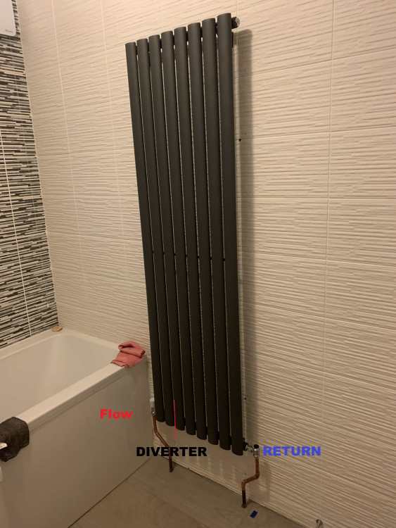
Not a problem - you shouldn’t need diverters for those rads (OK they are column rads by name but not in the modern sense) Just for giggles this was the view into the bottom tube of the column rad in my bathroom (first picture) So poor manufacturing tolerances meant opportunity for water to go straight thro from flow in to return out rather than be forced up the columns

-
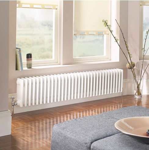
Just for clarification when I hear the term column rads I think of this But I have this suspicion based on a google that you mean
-
When I did the job I drained the system down in the summer (I had some other things I needed to do pipework wise) and I did all the EB4 Bodies at the same time (I had purchased them over the previous few months as and when I had a little spare in the household maintenance and repairs budget) If I had my time again I would go for the Flow setting version as the 6 position ones on a few rads are either on a setting to low (but the next setting is far too much) or on a setting too high (but the setting below is far too low) In fact I may well replace all my EB4's with the flow setting ones next year just to "fix the few" All my lock shields are wide open - The ability to control the flow thro a rad via the TRV body for me is so much better than trying to tweak lockshield valves that as soon as any TRV's in the system start to try to control room temps the circuit pressure changes and the lockshield valves are no longer set correctly
-
Several manufacturers do 130mm copies of the old style grundfos pumps Willo, Trident, Onyx - you can even get a BNIB Grundfos one it you search hard enough. I went for a DAB which has a little more functionality - recommended by my gas engineer because he won't fit the Alphas any more
-
Heating / Construction type.
marshian replied to Ryan 2023's topic in General Self Build & DIY Discussion
When you live in an area impacted by Huricanes and Tornados in the USA - you build cheap as it's cheaper to rebuild - Bricks and mortar don't fare any better when faced with a powerful force of nature -
Replacing them with what - same again?? Consider replacing them with a TRV body that either offers 6 adjustable flow settings (Drayton EB4 Bodies) https://www.toolstation.com/drayton-wiser-smart-radiator-thermostat/p50334?store=null&utm_source=googleshopping&utm_medium=feed&utm_campaign=googleshoppingfeed&gad_source=1&gclid=CjwKCAiAjp-7BhBZEiwAmh9rBcR1wEcxM8xrixvxTn8Bc1p-xOOXyXr6japIK4NNc0FIGr8jR9ikXhoCQlEQAvD_BwE Or the newer Flow control bodies https://www.toolstation.com/drayton-auto-balancing-valve/p19480?store=null&utm_source=googleshopping&utm_medium=feed&utm_campaign=googleshoppingfeed&gad_source=1&gclid=CjwKCAiAjp-7BhBZEiwAmh9rBTeH1kZaQ_VTDZBUakAjHVXcBD_mDBrVqQzDCF5dQqvOZAbLI3VfHhoCTp8QAvD_BwE Either of the above will enable you to run all the flow control at the TRV end and have the lockshield valve wide open OK so cycling isn't an issue Ref Diverters - A lot of cheaper column rads don't have diverters or if they do the quality control isn't great - I had three column rads that all had different return temps despite very similar flow temps - One of them I was lucky to get any drop at all. They basically work fine at higher flow temps when the heat rises up the columns faster than the flow thro the rad - but when flow temps are lower without effective diverters they don't work so well https://www.bestheating.com/milano-flow-diverter-15mm-inlet-chrome-63476?gad_source=1&gclid=CjwKCAiAjp-7BhBZEiwAmh9rBQMqlsl_fWADI-zBoT93tixIGwN2tEfg3xTNkQsP8lPsOfTaOWPSDxoCAOIQAvD_BwE&gclsrc=aw.ds These diverters fixed all of them to give a decent drop between flow and return and the rads get warm all over If you've purchased good quality column rads with clearly marked flow and return ends and the location of the diverter and they are piped up with the flow and return correctly you should be fine
-
Thank you for tidying the thread Agreed column rads need more flow but as they have a higher volume of water content they will work well at lower temps provided they have diverters (to stop short circuit) and you accept a slower warm up time Trv’s don’t last for ever - yep cheap ones are rubbish but the other thing to consider is cheap lockshields can be very non linear and make a circuit hard to balance - either get ones with a decent valve authority or go the other way and fit TRV bodies with flow control function
-
Screw the lock shields down to the point that the drop between flow and return on each rad is 12 deg at a flow temp of 60 and I reckon you will have a very unhappy boiler that short cycles a lot - so you will have a very high gas bill and a cold house. Max number of cycles per hour should not exceed 6 but lower than that is preferred As an example - my house 13 rads currently has a boiler flow temp of 33.8 deg C and the boiler is running for 15 mins on and just circulating for 20 so 2 cycles per hour (but its all close to temp now)
-
I have rads which a best only have a drop between flow and return of 3 deg (towel rails are rubbish for this) and other T22 rads that are 8 to 9 deg - only one rad in the house gets a drop of 10 deg and it a Triple panel, triple convector which is 1400 mm long by 700 mm high 12 deg is a legacy statement IMO from days of non condensing gas boilers - if you are using a condensing boiler you shouldn’t be running a flow temp above 55 leaving the boiler - the boiler is then always in condensing mode and more efficient. Now if your rads aren’t big enough at that flow temp then you have to go higher. 27 v 19 rads ok not as big as initially stated but still a large circuit on the column rads do they all have built in diverters - if they don’t it’s normally obvious - the bottom is hot the rest of the rad luke warm
-
@Dee please learn how to quote properly - write your responses under the quote of the post you are replying to - it’s horrible to untangle a mangled response where you’ve replied inside the quoted post (Thread now tidied )
-
dT is also related to flow temp - lower the flow temps the narrower the dT will be (for same circumstances)
-
Why is 12 deg important to you? At 70 deg flow temp you might see that at the boiler but not if you are running flow temps the allow the boiler to be in condensing mode all the time 27 rads is a lot of rads do you have control of the pump or is it inside the boiler - if external I’d try a faster pump speed - it could be that there just isn’t enough pump pressure to overcome the circuit resistance at the extreme ends of the system
-
I don’t think I’d be calling an engineer out if no repetative fault - £144 is a lot of money - will be an interesting conversation OP “here I saved screen shots of the fault” GE “no fault in system now - £144 please - cash or card” Good luck
-
I don’t think he meant a 19kW heat loss - he meant the gas engineer proposed a 19kW boiler and he asked for 32kW to be installed
-
The oversize element (32 v 19kW) doesn’t matter it can modulate to a silly low figure cos Viessmann and if it’s a combi you may need the 32kW for HW. The “sue Viessmann” made me laugh a lot - it’s thrown up an error code for the first time in 2.5 years - it’s under warranty if a reset (power down) fixed it then move on with your life it was a glitch - if it needs a reset every day or week then get an engineer in
-
Oooff - you’ve done well in that age building - well done
-
I’d want to be closer to 40 deg C flow temp to move to a HP - 50 is at the top end of HP range and you might not get the COP you would need to break even on energy cost (3.0 to 3.5 unless you have a cheaper tariff for electrickery)
-
Yes it cycles more ~32 fires/starts in 24 hr period with a higher WC and sheduled heating that would be ~12 cycles in 24 hrs however I am not seeing a huge increase in gas consumption with the current boiler (the prev glow worm yes big increase when cycling more than 3 cycles per hour but it had a 10kW min output)
-
schedule heating (on/off/on/off) I’m running WC curve of 1.4 Constant on (with setback temps instead of off) I’m running a WC curve of 0.8 I’m working my way towards on (no setbacks) and I think that will be a WC curve of 0.7 Logging HDD data v gas consumption (minus HW) I thing last stage will be 5 to 10% more usage but house comfort will be better (more heat pump like)


