


marshian
-
Posts
1590 -
Joined
-
Last visited
-
Days Won
6
Everything posted by marshian
-
Well time to round this out (Not quite there but damn close) No mater what I did with the Wiser Hub (controller) - All Off, HW On, HW Off, CH On, CH Off or Both CH and HW On the wire from the wiser unit to the wiring centre to trigger the HW was live all the time. I was completely confused by this as it shouldn't be live unless the timer is calling for HW but I checked the wiring instructions and it was all wired correctly 3 for HW and 4 for CH I swapped to a different (spare wire) - same result 240V all the time unless the power to everything was killed The CH wire is only live when the timer and the room stat is calling for heat Every time I check wiring in the wiring centre or remove the Wiser Hub I switch off the power to it all at the Fused Spur that feeds it all I don't know why I did what I did next but I took the Wiser hub off the universal back plate without powering down and I heard an audible click and I stopped - a penny (very large one dropped) - selecting CH or HW had always made an audible click but since the boiler install and change of wiring that had been missing for HW the light comes on but no audible click. I switched off the fused spur - re-attached the Wiser hub and if I selected HW I got a audible click, CH again I got an audible click Going up to the wiring centre with nothing selected on the hub I had no power to either HW or CH signal wires Selecting HW gave me 240 volts and same with CH with nothing selected I got no Volts on either HW or CH My only thought is that somehow the relay or contactor for HW had stuck closed and even powering down the unit was not causing it it open. Anyway everything now works and just need the gas engineer to confirm with Viessmann that a switched live back to the boiler is needed (I'm damn sure it is but I'm not about to fit that) I actually need to think about how the boiler gets that in summer or if heating water outside of the CH period because I can't have both CH and HW linked to the same switched live signal to the boiler or CH will drive HW I might have to either A. think about a relay solution or B. think about a switch (Summer / Winter setting) I can only have one SL wire at the boiler so for Summer the SL comes from the HW side but for winter when I only heat water during the CH timed period it can come from the CH side.
-
And there is my problem - I got the only Viessmann trained gas engineer for 50 mile radius to do the job - the other installer 50 miles away didn't want to quote because the distance made it not worth his while................. Maybe I should ask Adam from heat geek if he fancies a boiler challenge............
-
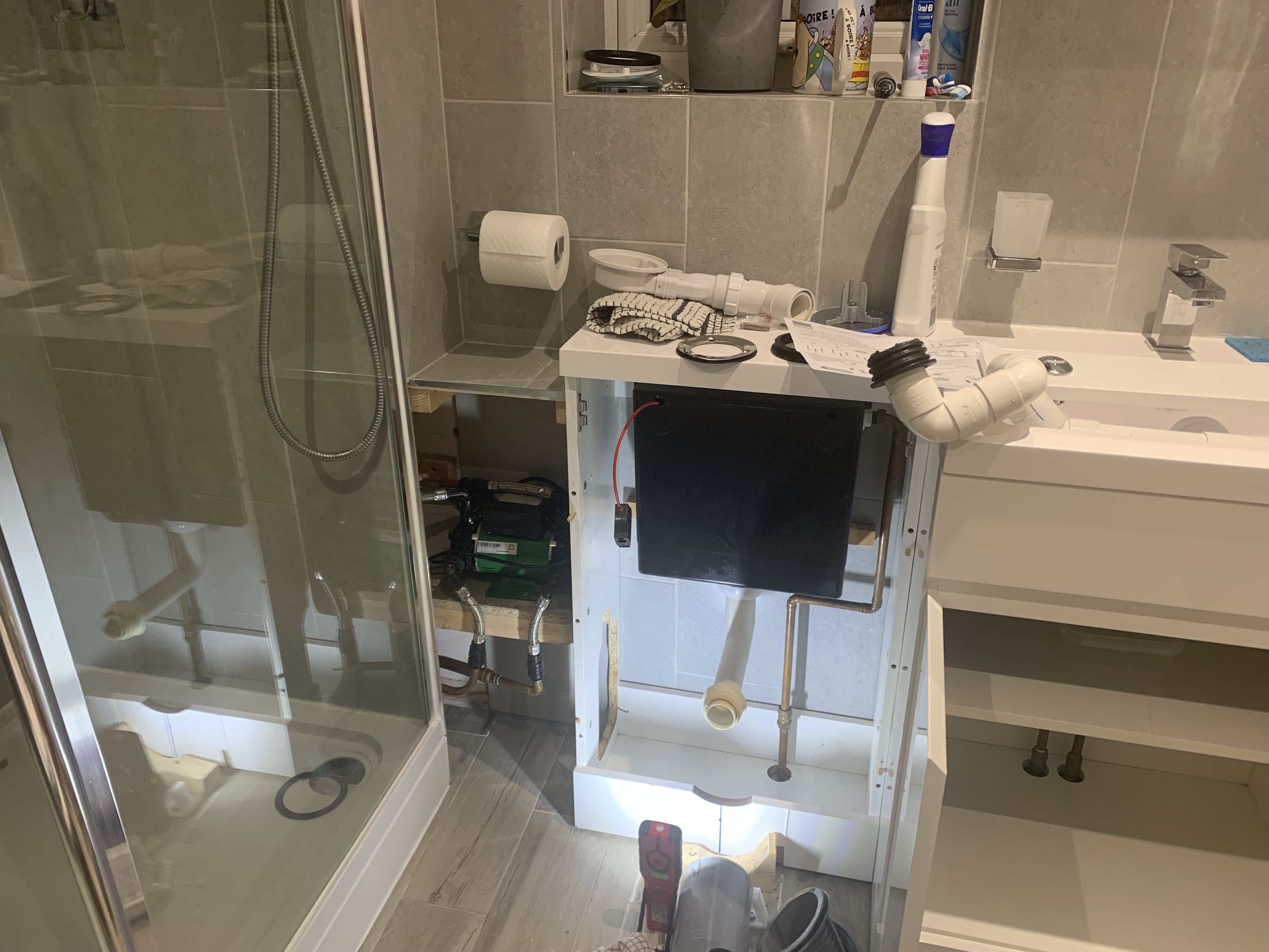
Sorry had to rip apart my bath room to replace a shower waste that was letting in smells So connected (Not me) but AFAIK Outside temp sensor yes HW Demand box Power to the Boiler (Live, Neutral and Earth) After that sorry but not a clue
-
 Just to round the calibration element of the thread - I’ve had both sensors over a NaCl slushie for a couple of days at room temp one required an adjustment of 2.7 and the other 4.5 (both cases they were over reading) so I’m a smidge less concerned about my humidity levels now thank you @Sparrowhawk
 -
Sorry for slow reply - my attention has been diverted to bathroom issues shower waste needed replacing and access was too tight with the soil pipe in the way - luckily I did the bathroom myself so knew how it all went together Later today I’ll check out the boiler connections

-
as the link is external to the PCB I decided to remove it……. No pump at all
-
Highly likely - That will be down to the gas engineer to resolve - I'm absolutely fine with doing everything outside the boiler - not so fine with stuff inside it.................
-
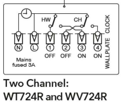
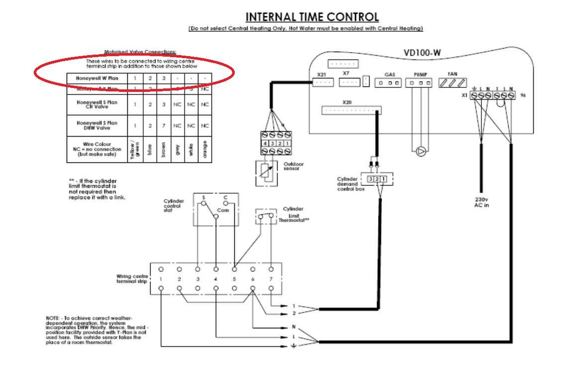
Whoa @JohnMo That link has this diagram - It's not in any of the documentation I got with the boiler or HWD box or weather sensor........... Is a W Plan similar to X plan with a 3 wire NO CH Valve??

-
I’m trying very hard to do three things 1. understand how it works 2. Save the life of a fuse by not getting it wrong 3. Keep the smoke inside the wires thank you for your input but this is not my strong suit so I will be painfully slow in progress
-
What connection?? boiler has Direct control of the pump HWD box wired in Weather Compensation sensor wired in The boiler has been “told” to run in weather compensated operation mode The link wire is still in place and I think it’s running on a permenant live and Neutral only with no switched live in sight But as I’ve said electrickery is not my strong point - if it’s got oil or water in it or it needs to fabricated in steel or wood or whatever I’m fine with it
-
it’s connected and it sort of works - just haven’t documented that section of the wiring on my schematic sort of works………. I currently have to turn the boiler off to stop CH - it leaves the pump on 24/7 even if the controller says all good house up to temp lets wait for the call for more heat flow temp of 32 deg C today and all rooms are at target temp on trv’s so all the flow is going thro the bypass right now so I’ve stopped the boiler in the ViCare app
-
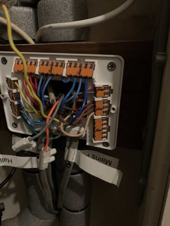
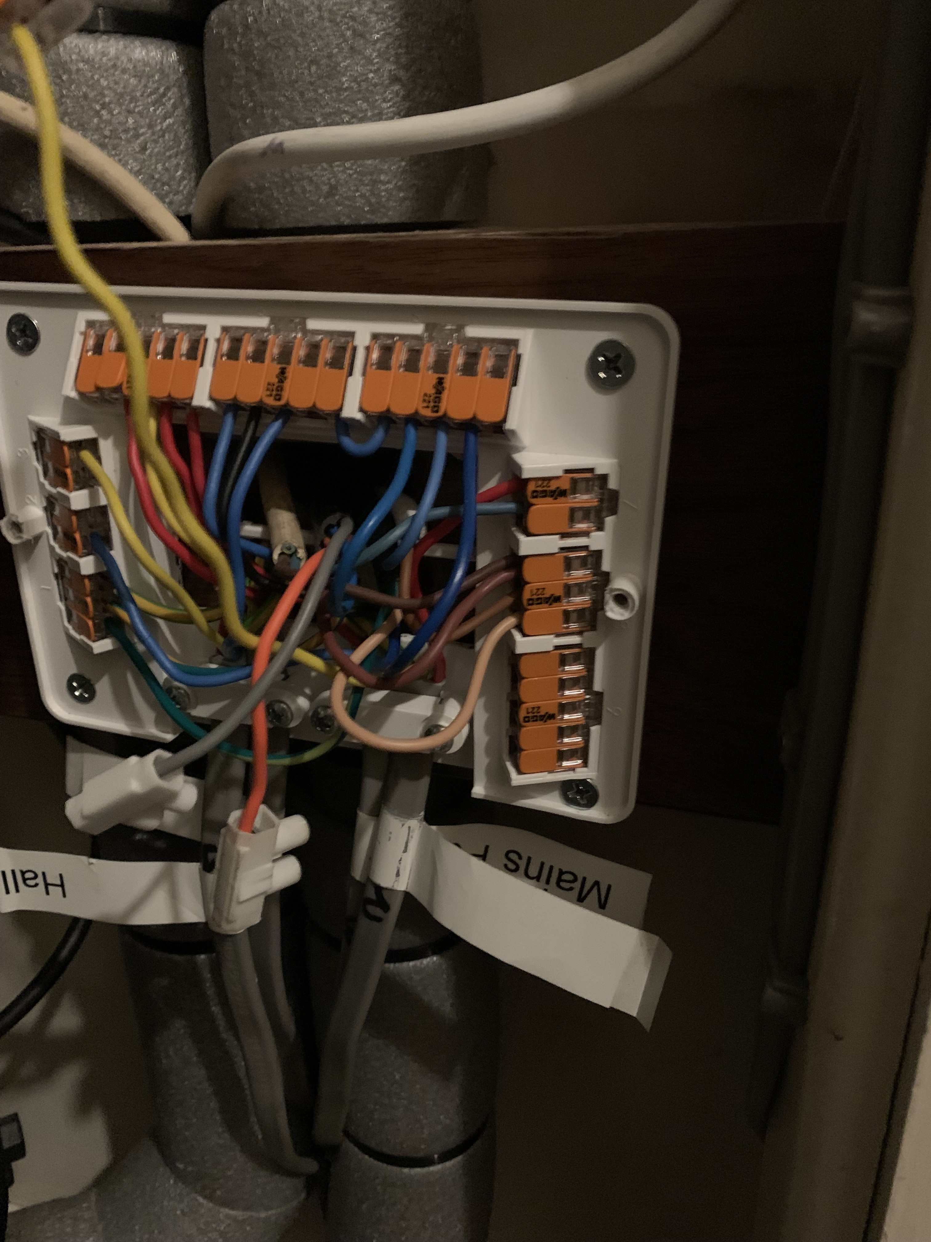
Current state of wiring centre orange now located in bottom right and linked to HWD box grey is now in the live lot (top row left side) Reminds me - all the grey cables at the bottom were clamped before the install after none were clamped and the clamps were gone….. as a result I bought another L16 wiring centre to get new clamps and screws because I was less than happy about unclamped wires in a traffic area (SWMBO) keeps her ironing board and irons on the floor and shes a bit heavy handed Remember this is a Viessmann trained installer - only one in 50 mile radius I hate ending posts negatively - shat’s done is done I’ve clearly reached a point where I need to do this myself and any help or advice in this direction is appreciated and I can move forward positively
-
Just to repeat - I asked for X plan - I got S plan (2 NC zone valves) with weather compensation (turned off because I like HW not CW) and set it up with a 55 deg flow temp no HWD box no wifi interface (was on back order) Installer came back with one new NO zone valve, HWD box (after I told him the part numbers for both) and said will you order it or shall I?) and the long awaited for wifi module he’s had two opportunities to get it working right on x plan DHWP and hasn’t really got it right - I still have issues with control on CH side so I revert to what I often have to do “If I want a job doing properly I need to do it myself’ DIY means starting from scratch working out what all the wires do and drawing up a schematic that makes sense to me - Electrics are not my strong point but so far no fuses have been sacrificed to my electrickery knowledge quest
-
you’re a very clever chap but either I am really rubbish at explaining stuff (and I can accept that criticism if I am) or your reading and comprehension skills are a bit poor and I’m going to assume it’s the former rather than the later for now As I said in earlier post CH side is not fnished in the drawing - I’ve just managed to get the HW side working as it should along with the transfer from CH to HW and back to CH having completed HW - not finished would account for some missing wires OK
-
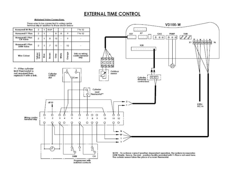
You do realise "my drawing" is of all the wiring centre (well when I finish it) and what you have posted is a diagram of how the HW demand box integrates with the boiler 😞 I must admit I've borrowed the base drawing from an S plan which is what the gas engineer set the system up to work as despite being asked to set it up as X plan!!! 51011_01-mBox-L32-S-Plan-connection-drawing-FRAMELESS.pdf
-
I must have watched that video a bunch of times and I've not spotted that element Annoyingly the only video that Syzmon has done that featured a Viessmann 100-W B1GA turned into a little whinge fest about how he wasn't impressed about the fact the HW demand box and wifi module were add on units and the boiler front cover didn't have a sound insulation panel in it like the system or combi boilers did. He was making a valid points The HW demand box is a bit of an add on The Wifi module is hard to fit in the space and route nicely - if the ribbon cable was 2 cm longer it could be routed away from everything and look much neater than crossing the PCB at 45 deg When heating HW at 100% modulation the 16kW rated boiler I have is throwing 19kW and 80 deg flow temp at the HW circuit and it's nowhere near as quiet as it is when it's doing CH at 3.2 kW and 37 deg C I didn't want to convert to a 4 pipe system for all the disruption that caused and I wanted a boiler I could hide in a 300mm dept cupboard because SWIMBO wants to change the kitchen from white to black/dark gray and a white boiler on show would look crap Sometimes we have to compromise to someone else's needs/wants
-
But tying the two browns together does that too doesn't it?? Not being confrontational here - if I'm not doing the right thing then I'm happy to learn why I need to do it a different way but to my mind both ways achieve the same result I used the orange to power the HW demand box so I could have that in it's own section on the wiring centre because it's Viessmann thing to have an additional HW demand box.
-
I need a feed to go to the HW Demand box Putting Brown to Brown works and keeps the HW demand part simple CH in normal operation the NO valve is consuming no power and idle When HW is demanded - NC HW Valve and NO CH Valve share the Brown so both effectively energise CH Closes from Open HW Opens from closed Why wouldn't that be OK?
-
It is a good video But "Ideal Vogue" use 2 switched lives
-
I can't work out how to split up a long list of questions into individual responses so see below Yes (EB4 TRV bodies) and flow rates are suitable for lower flow temps When all rads in circuit - flow rate is about 1.1 m3/hr When TRV's start to cut in it drops down to around 0.5 m3/hr I'm not looking for 20 deg drop across any of my rads at a flow temp of 37 deg C - it would be impossible - the return temp would be less than the room target (or actual temp) Using heat geek table is a better guide to expected drop across the rads (or diff between flow and return) Flow Temp Return Temp Diff 55 38.5 16.5 50 35.0 15.0 45 31.5 13.5 40 28.0 12.0 35 24.5 10.5 Rads are sized to the rooms and all but one room they are oversized for the flow temps currently being used I'm not blaming anything on the boiler - I'm seriously impressed with the Viessmann 100-W "Heat only" - But I do have some control issues which I am working thro Done IR wall floor and ceiling checks - this thread is not about heat loss or improving it - I know what I need to do there and it comes after boiler control issues are sorted
-
Indeed it is - thank you sir One issue I see is that it uses a relay arrangement which I'm trying to avoid as I think it's not needed with a NO CH valve and a NC HW valve That diagram uses 2 NC Valves for CH and HW (hence the linking of the two oranges to energise boiler and pump) But It gives me a start that is slightly easier for me to get my head round than the Viessmann diagram (which I find really complicated) Not sure the world is ready for how far I've got (not complete) drawing up the X plan with crayons (to the same format as the std Wago (L16 wiring centre) but I'll share it so you can laugh
.thumb.jpg.3e18990ef799d7704e178cb9404f25aa.jpg)
-
Right I'm resigned to sorting out the control side of the boiler myself HW demand is now working fine - ramps up temp and modulation and tops up a tank of water to 55 deg in 15 mins so no issues there The problems I have are I can't find a wiring diagram where a NO valve is used for CH and a NC valve is used for HW Often X plans are on boilers where HW/CH selection is done with 2 switched lives Closest I can find is However whilst it gives some valve wiring options it doesn't cover the X plan set up I don’t have an NTC sensor (Shown as Cylinder limit Thermostat) so ignore that The HW tank supply has the 2 port Normally Closed valve NC Valve has 5 Wires Live (Brown), Neutral (Blue), Earth (Yellow/Green), Grey (Live feed for the internal Switch) and Orange (240V output when valve is fully open) The CH supply feed has a 2 Port Normally Open Valve NO valve has 3 Wires Live Brown), Neutral (Blue) and Earth (Yellow/Green) I've set that side up so when the Cyl Stat calls for heat the brown “Live” powers up the Normally Closed Valve to Open (the grey wire has permanent power but it only goes to an internal switch that makes when the valve is fully open and puts 240v to the Orange – the power from that goes to the Cylinder demand box to tell the boiler it it’s doing HW – it ramps up to 80 deg C and modulates as high as it can based on return temps to heat the HW cylinder (coil) to the target stat temp in the shortest time possible The same signal Live also powers the Brown for the Normally Open Zone valve for heating so it closes stopping elevated temp HW going round the CH circuit As soon as the tank stat is satisfied the live circuit to the zone valve is removed, the HW zone valve closes, the CH zone valve opens – the Live feed to the HW demand box is removed and the boiler reverts to weather compensated flow temps The only other issue on the HW side is if the HW tank stat picks up a significant drop in temp (the hysteresis is quite broad) then without anything being on the HW valve will open and the CH valve will close and the pump will start so I think I have a wiring issue in either wiring centre, Heating controller or very possibly Boiler.
-
And the best bit tonight I've established that in the current configuration giving the boiler control of the pump means it runs 24/7 regardless of a call for heat!!!
-
most radiators get hot first at the lockshield valve
marshian replied to Question's topic in Central Heating (Radiators)
When it was all we had to control the flow thro the rads you had one at each end of the rad -
And back to a dumb boiler again Pump wired directly to the boiler (so it has control) still getting 75 fault codes so that was a lot of effort for no gain HWD box reactivated - worked brilliantly - fired up the boiler and ramped up the power - tank of HW generated in 25 mins Switched over to CH in weather compensated mode - and the bloody boiler thinks it's still doing HW so instead of a 37 deg flow temp it goes straight for 80 deg........... On the positive side new pipework for flow and return to the airing cupboard is all done so at least I can put the floor back down

.jpg.31c26a868d7e7913f4854d9753adb177.jpg)