


Beelbeebub
-
Posts
1521 -
Joined
-
Last visited
-
Days Won
11
Everything posted by Beelbeebub
-
Beginning of the end for MCS?
Beelbeebub replied to sharpener's topic in Air Source Heat Pumps (ASHP)
Dense urban areas are not famed for their quiet sound environments. Where is the DEFRA investigation into traffic noise? Aircraft noise? Train noise? Having lived in London where I got all 3 on a regular basis plus general city noise like sirens, shouting, reversing beeps etc, I would have ahppily traded any one of those for a constant hum from a heatpump. -
Joules ASHP - Controls for towels rails & rads + UFH
Beelbeebub replied to Andeh's topic in Air Source Heat Pumps (ASHP)
The 2 port valves are spring loaded. No power to them they are closed. If you put 240v across them, the motor opens the valve. Asong as 240 v is on the valve the motor apply torque and the valve stays open. When the valve opens a cam inside pushes a microswitch and turns it on. So you wire your valve up to 240v, with the thermostat as a switch. When the thermostat calls for heat, it closes the circuit, 240v is put across the motor which opens the valve. The microswitch is wired to the bit that demands the boiler (or in this case the HP). If your garage thermostat demands heat, it closes, garage some valve opens and the valve microswitch calls for heat. If your towel rail timer calls fo heat, it closes, towel rail valve motor actuate, opens valve and closes the microswitch calling for heat. Basically if any zone valve is actuated the boiler/HP is called to provide heat. -
Joules ASHP - Controls for towels rails & rads + UFH
Beelbeebub replied to Andeh's topic in Air Source Heat Pumps (ASHP)
OK shot in the dark. The Joules cylinder controller has 3 zones. You close a circuit (thermostat) on z1 and it does the necessary, opens the appropriate zone valve, calls for hear from the HP etc. If you do the same with Z2, it all happens with Z2 etc. And same with Z3. Can you not wire up ZG (garage) and ZT(towel rail) valves to their respective zone valves and then have the microswitch in those zone valves wired in parallel to the Z3 input. ZT and ZG are fed from Z3. The if ZT is called for, the ZT valve will open, and also close the switch calling Z3 which activates opens Z3, calls for heat. The food then goes down the ZT loop Likewise for ZG. That said I agree with @JohnMo prob best just to use electric elements to heat the towel rails if you need them outside of central heating times. -
Snap! 😁
-
Could you run a return in 15mm (or even 10mm) plastic back from the remote bathroom and have a hit water circulatory pump so you get instant hot water. If you slaved it to the light switch (or used a wireless switch on the wall -try quintec ones) then the pump would only run when you turned the light on.
-
I think (and I may be wrong) there are mixers that are "scald safe". The idea is that if, for some reason, the cold supply only were to be interrupted the shower will shut down completely and there is no chance of some hot water getting through with no cold to mix down with. The physical design to achieve this always lets some cold through so the min hot water temp is higher. Maybe that's the discrepancy?
-
I get the analogy with a hot water pipe and a tap at the end (partly because my one kitchen tap is that tap!😁). I'm not sure the heating of the various components is a major issue, especially as they are typically insulated. But also because the thermal mass of the compressor, pipes etc is relatively small vs the load (house). The unused water in the pipes outside the thermal envelope is a bigger issue. I can imagine a pump se way away from the house with big bore pipes might suffer more than one right next to the house. Things like the pipe runs, insulation of components and thermal mass of the house will be important, and will impact the cycle time below which inefficiency becomes intolerable. One aspect will be the thermal mass of the house. It may be that running a little hotter and transferring a little bit more heat than the losses would require is a better strategy than just turning off. If you "overheat" the house by 0.3C will anyone notice? This may be an area where pure "open loop" weather compensation loses and a slightly more pragmatic algorithm focused on maximum efficency at stating above a certain temp (even if that means being a little bit more above than you would normally consider) might win.
-
It seems common knowledge that cycling is bad for efficency and longevity. But why? What are the mechanisms of loss? What are the accelerated wear mechanisms? I get on the older shaded pole single speed motors there were contractors, capacitors and centrifugal switches that might have a finite number of operations. Surge current wouod also cause issues. But modern units use inverters with soft start and effectively infinite switching (certainly in the context of start stop) So what are the problems with mild cycling?
-
Maybe their swing compressor design has lower blown past losses on startup?
-
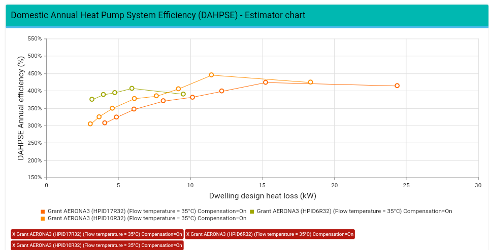
Not sure if this has been posted before https://tools.bregroup.com/heatpumpefficiency/index.jsp Appears BRE have developed an efficency predictor tool based on more typical UK conditions than the SCOP calculation that manufacturers use in their literature. Their calculation also includes system loads like pumps and backup heating as well as hot water loads. One curiosity and I have to dig into the details) is that it appears the seasonal efficency (their version of SCOP) improves with undersized units using direct electric backup heaters for the few occasions needed. Their explanation is the reduction in cycling for the rest of the year more than compensates for the few days of inefficient direct heater use.
-
aroTHERM Plus DHW Flow Temperature
Beelbeebub replied to Dan F's topic in Air Source Heat Pumps (ASHP)
All valid points, But all I've described is a standard vented cylinder with an "afterburner" to boost the temp So all the objections are the same as for a standard UVC set up etc. They are not differential objections. As for the flue, in cases where the flue isn't in a convenient location,.you just block it up and drill a convenient hole in the wall, like you do now -
aroTHERM Plus DHW Flow Temperature
Beelbeebub replied to Dan F's topic in Air Source Heat Pumps (ASHP)
Yeah, not much difference, except packaging. Key bit would be that it was a "box on the wall" hanging where the boiler was. The pipes from outside would come in via the flue (possibly in an insulated duct, so looking exactly like a flue) Flow and return would come out the bottom, cold feed in and DHW out would also come out the bottom. The drain would go where the condensate line goes. Plus a bigger 10kw freed from the consumer unit. This is for the "direct swap with a combi" cases. Gives near as possible to combi like performance and packaging. People existing tanks or space for a new tank could have a UVC or VC as they desire. -
aroTHERM Plus DHW Flow Temperature
Beelbeebub replied to Dan F's topic in Air Source Heat Pumps (ASHP)
Damn! Meant to draw one but forgot! Yes a vent pipe from top of tank back into cistern. -
aroTHERM Plus DHW Flow Temperature
Beelbeebub replied to Dan F's topic in Air Source Heat Pumps (ASHP)
This is just for small volume (sub 50L) "boiler" wall box. To provide as close to a "combi" experience as possible. If you have space for a tank in the airing cupboard, then a bigger version with or without the electric heater is possible. If we ditched the requirement for "unlimited hot water at high flow rates" it makes the whole heatpump installation a lot easier. No diverter valves, no G3, no overflows, no tank primaries just a 10kw box under the sink. This would also make air to air heatpumps very competitive. One interesting possibility would be if home batteries become more of a thing, a 10kwh battery could supplement the 10kw mains for 1 hour and provide enough electrical power for a 20kw instantaneous water heater. The 10kwh battery would also work with the home electrical system to provide load shedding, uninterruptible power, PV storage and all the good things home batteries can provide.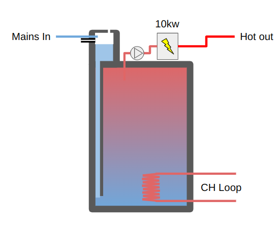
-
aroTHERM Plus DHW Flow Temperature
Beelbeebub replied to Dan F's topic in Air Source Heat Pumps (ASHP)
I think @JamesPa means, is "Fully sealed" - a tight fitting lid for hygiene rather than pressure sealed. The pumps are commodity items, they have a small accumulator and check valve built in. Fit and forget. If it breaks, swap out. "No header tank" - i think he means not the traditional large F&E tank in the loft. If you have a pumped system you don't need the F&E tank in the loft anymore. It doesn't need to be as big as an 8l capacity would be ample to account for expansion. That could be easily integrated into the top of the tank even if it's nitnthe highest point in the system. The ballcock would probably do, but you'd probably want something a bit more advanced, both to start and stop quicky and to deliver high flows quietly. Maybe something more like modern toilet fill valves (also more compact). -
aroTHERM Plus DHW Flow Temperature
Beelbeebub replied to Dan F's topic in Air Source Heat Pumps (ASHP)
A typical shower uses 10lpm. With low flow aerating head we can get that down to 9lpm fairly easily. A reasonable sized heat pump can punt out 9kw at 45C using 3kw of power. If that flows into the "buffer/TS" vessel it should be able to heat the incoming mains by 14C. A 10kw instantaneous heater on top of that will raise another 15C for a total rise of 29C That should be enough to raise 9lpm by from 10C (minimum) to 39C, pretty much where you need for a shower. Reduce the flow down to 8 and the total rise becomes 33C for a 43C shower (and that assumes a fairly cold incoming main). In the summer the HP can kick out 10 or even 11kw. And a 9 kw HP, especially with a 50-100l buffer vessel should be small enough for all but the smallest properties. A rectangular 50l buffer vessel with a 10kw instantaneous heater could be packaged into a 85l box about 0.7x0.4x0.3 ie about the size of a boiler. So you have a sub 1mx1mx0.4m monoblock outside connected to a "boiler" in the same place as the combi boiler. The "boiler" is fed by a 40A spur (shower) and the HP by a 20A spur. You get infinite shower water at 8lpm and run your CH at whatever flow temp you like (eg use weather compensation), though higher flow temps would give better DHW performance at the expense of efficiency. The only issue would be your HP hitting defrost at low temps. In this case your would still get hot water but the flow rate might have to drop whilst the 9kw from the HP is removed. If the defrost cycle was short enough and didn't exhaust the buffer, you would still be able to operate, just that the flow rate would be limited by temp rise achievable by 10kw plus whatever the average output of the HP was over the charge/defrost cycle. Of course a bigger buffer/TS would help but that would be used where a large cylinder wasn't a problem, the small buffer would be specifically for "like for like" Combi replacements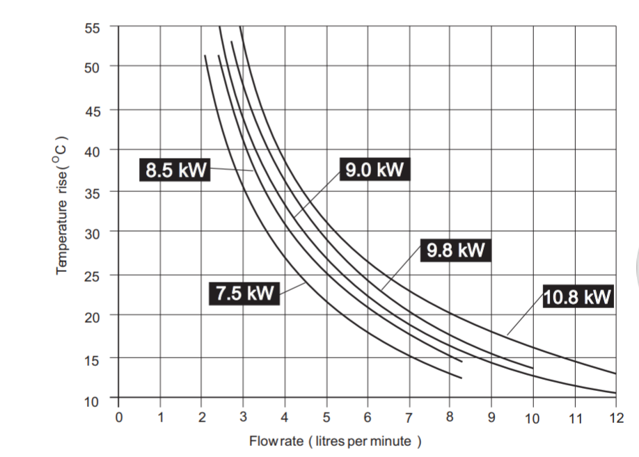
-
aroTHERM Plus DHW Flow Temperature
Beelbeebub replied to Dan F's topic in Air Source Heat Pumps (ASHP)
What sort of kw heat transfer can they support? -
aroTHERM Plus DHW Flow Temperature
Beelbeebub replied to Dan F's topic in Air Source Heat Pumps (ASHP)
How about, storing water in a pressurised TS (basically a buffer vessel) at whatever the CH flow temp is, or maybe a touch above. Anything from mid 20's. This can also act as the buffer to avoid cycling and the defrost volumiser. Then via a simple coil you preheat the hot water circuit to whatever temp the buffer/TS can manage before sending it on to the instantaneous heater unit. If incoming mains is 15C and you want your shower at 45C that's a 30C rise or 3.5-5lpm But if you manage to preheat the water to 25C it's only 20C and you can achive 5-8lpm. If your buffer/volumiser is at 35C, then even you're talking 8lpm even for a weedy 7.5kw shower
-
Hummm, the second set of data is broadly consistent with my "assume a 22mm coiled pipe" calculations, but it looks like they have upped the could size. I note the first set of data.was.for the "B3V3" cylinders, whilst the second is for the "D3V3". Maybe the difference is the "D3" series use larger (longer) coils. Hence the discrepancy.
-
aroTHERM Plus DHW Flow Temperature
Beelbeebub replied to Dan F's topic in Air Source Heat Pumps (ASHP)
The thing about Willis heaters (and any immersion heater) is they produce high temp water, so the effective volume of the cylinder is way higher when it delivers water at 45C. With direct electric there is no penalty for providing high temperature. 3kwh is 3kwh regardless of it being lots of 40C water or less 80C water at 100% efficiency. Electric tanks always store water at +65C So your 120l vented tank at 65C gives way more like 160l or 180l of 45C bath water. You can do that with a HP, but at a penalty. So storing at 45C is the lowest you can go, and your 120l cylinder that was ok on electric is a bit too small on a HP. (Except after the legionella cycle!) -
Napkin calculations.... if they use a 22mm copper pipe for the coil, 2.3 l is a bit over 7m. 22mm pip has an area of 0.07m2 per meter so the coil area would be about 0.5m If they used 15mm pipe you would have 16m of pipe so the area would be 0.75m of coil (though the flow resistance would be higher) Corrugations would increase the surface area maybe by 2x, but even so it seems a pretty small coil compared to what they specify.
-
aroTHERM Plus DHW Flow Temperature
Beelbeebub replied to Dan F's topic in Air Source Heat Pumps (ASHP)
Yes. Especially if the storage temp is very low, which you want it to be for HPs I think that's why UVCs (with or without G3!😁) Will probably be the default. They are fairly widely used now anyway. The alternative is the vented cylinder, but that may need a pressuring pump. The pump would make it directly comparable to a UVC, but may net be needed, there are quite a few places that operate on VC's at the moment. Or you could have direct on demand electric hot water, this is definitely a possibility if you don't need a bath filling eg small flats. -
Live scenes as Tony passes feedback up the chain.....

-
aroTHERM Plus DHW Flow Temperature
Beelbeebub replied to Dan F's topic in Air Source Heat Pumps (ASHP)
Yes, but I wouldn't underestimate the difficulty of getting the pump speed control just right when you get into the real world of sensor lag, pump flow rate floors, varying temp inputs and flow rates etc. The pump to control all that would be at least the same as an off the shelf pressure boost pump but not off the shelf. Here's my thought process The tank for the thermal store and the vented cylinder are more or less the same thing, so the argument "you can do X" to one applies to the other i.e it's a tie between the two systems in this area If you use a PHX both need a pump (boost pressure or feed PHX) but the vented cylinder pump is off the shelf whilst the TS + PHX pump is more bespoke. So advantage VC The vented cylinder needs a ball valve, feed tank etc, relatively simple and cheap, the TS needs a PHX, simple and fairly commodity, so I'd say a tie. The VC wins on efficiency (as we discussed). The TS can approach the VC on this front but only at the expense of complexity. On the plus side for the TS, you wouldn't need to do legionella cycles. For the TS, stratification is absolutely key. Without it, your efficency drops relative to VC. For VC, stratification is also important but easier to achieve. And.yes, experiments would be great!😀 It's entirely possible the differences in prices and performance are fairly negligible so the decision is down to other things like availability, space, exact circumstances etc -
aroTHERM Plus DHW Flow Temperature
Beelbeebub replied to Dan F's topic in Air Source Heat Pumps (ASHP)
I'm not suggesting the cylinders don't have G3 features like prvs etc. IMHO, we are somewhat overcautious when it comes to invented cylinders. The design of the cylinders, and in particular the safety group, *is* important. But it is by and large done by prepackaged devices that are matched to the cylinder at manufacture. The requirements for G3 "tickets".and annual inspection seems a little over the top given there is actually nothing the inspection does. It's basically a visual check and a check of the expansion vessel. So there may be a small benefit to relaxing the regulations in the context of HP.installs. But it's fairly moot, to G3 or not to G3 is a pretty small issue in the grand scheme and the potential to drop it in certain limited.circumstance is a.footnote.
