sharpener
-
Posts
1487 -
Joined
-
Last visited
-
Days Won
1
Everything posted by sharpener
-
Solar PV, combi boiler and wood stove with a back boiler?
sharpener replied to Hannah77's topic in Photovoltaics (PV)
Are you thinking of a big thermal store with the DHW coming through a hi-gain coil inside it? This would suit your WBS as well. But not easy to see how you would control all this for max efficiency. Previously we had an oil boiler feeding a conventional h.w. coil, we had the stat set 5K lower than the immersion stat so if there was enough PV the boiler would not cut in. In winter the boiler was timed to test this at 1700 which was after the PV had finished but early enough to provide for showers before dinner. In summer less of a problem and we rarely needed the boiler at all. You could use the combi in a similar way. But as @JohnMo says it is all getting very complicated. Personally I wouldn't try and integrate the WBS unless you have a massive supply of free wood. Have heard they do not burn well with the cooling effect of a back boiler. Sounds like 2kW or so. Midsummer Wholesale and others have PV roof planners on their web sites. IME that won't be enough to provide a regular supply of hot water and charge a useful size battery, we had nearly twice that to begin with and now have 4x. -
Need a copy of paperwork to submit to dno for panels
sharpener replied to CalvinHobbes's topic in Photovoltaics (PV)
Just so. The 5kVA Victron has a 50A passthrough capability so is just about big enough to supply the whole house with any available combination of grid and battery. If I need to I can put the garage on bypass to supply the EVCS direct from the grid. Yes. This was how it was wired before I added the battery system. One advantage is the original W roof PV can keep generating in a blackout, the Victron provides a virtual grid which it can sync to. Having re-read the whole thread I may have assumed the OP was asking about a hybrid system. If this wasn't the case and it concerns plain old PV then you can ignore all the diverting stuff about the IET CoP. -
Need a copy of paperwork to submit to dno for panels
sharpener replied to CalvinHobbes's topic in Photovoltaics (PV)
Not very simple but here you are: The IET CoP was fairly new when I installed the battery system in 2022 and this requirement was in the first edition. It was also there in the 2nd. Neither of them had in the "typical configurations" a suitable diagram for the Victron inverters which have separate AC in and AC Out (which since they had a rep on the editorial panel I don't understand). I do not know about the 3rd edition. With the more common battery inverters (GivEnergy, Solax etc) with a single point of connection you would have a separate garage unit for it teed into the main meter tails. There is another requirement here, any RCD or RCBO needs to be the new bi-directional type, earlier models only work with the power flow in the "correct" direction i.e. from line terminals to load terminals. Did it include a battery in 2012? This CoP applies only to EESS, it does not cover PV-only installations. The AC-coupled PV on our W roof was installed in 2011; I fitted an extra mini-CU for it and a dedicated socket for the freezer before the installers came. I don't know how they would have wired it if I hadn't. Originally they were not protected by any RCD. Still aren't if the Victron battery inverter is bypassed when not in service. Depending on the internal physical layout you could maybe fit an RCBO connected directly to the incoming meter tails. Ideally you would move the main RCD and fit the new RCBO on the other side of it so it is obvious it is not supplied through it. We have done similar with the RCD for the garage supply (Crabtree Loadstar unit, physically mounted on the DIN rail in the Starbreaker CU housing but not plugged into the load side busbar). Certainly looks a lot neater than the usual nest of Henley blocks. Recently had a long discussion re all this with the installers on how to wire in the heat pump. Their original plan would have meant it could not run off the inverter at all so could not use the batteries for time shifting. End result was a modification of what is shown in the diagram.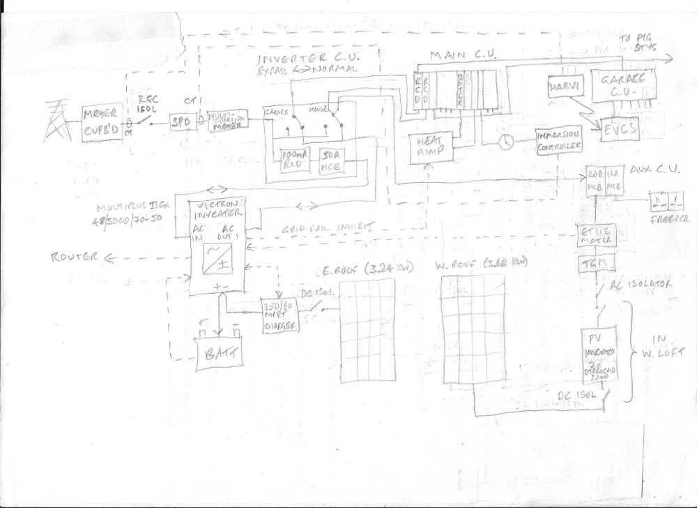
-
Solar PV, combi boiler and wood stove with a back boiler?
sharpener replied to Hannah77's topic in Photovoltaics (PV)
Breathing in the high level of particulate matter in the smoke I think. Perhaps more of a risk to your neighbours than yourself so long as you have the requisite supply of combustion air from outdoors. -
Need a copy of paperwork to submit to dno for panels
sharpener replied to CalvinHobbes's topic in Photovoltaics (PV)
The above schematics all appear to show the inverter coming off the existing consumer unit. Though often seen, the IET Code of Practice does not allow this, you need to fit a separate CU so it does not share an RCD with the existing domestic loads. -
Solar PV, combi boiler and wood stove with a back boiler?
sharpener replied to Hannah77's topic in Photovoltaics (PV)
WBS should have the priority when it is operating so there is some outlet for its heat. So set the immersion heater stat quite low to hold off the PV when stove is in use. You might want to inhibit it manually on a sunny winter's day if you know you are going to run the WBS all evening, difficult to automate unless your usage pattern is very predictable. Bear in mind there won't be much PV in winter and it is more valuable as electricity to charge the battery than to produce hot water. Check for limitations in the instructions for the WBS you are thinking of buying. For example our Woodwarm stove can only be used with an open-vented cylinder, which would require an expansion tank in the loft, and needs a thermal store if you are using it for underfloor heating. Don't know if you can take the output from the h.w. tank via the combi so it will top up the temperature only if necessary, check the instructions for it. Or you could have a diverter valve operated by a tank stat that determines whether it is hot enough. Most competent heating engineers would be able to sort this. -
Quote for ashp - didnt expect that much!
sharpener replied to TheMitchells's topic in Air Source Heat Pumps (ASHP)
Yes. The plumber and apprentice did this while the lead person did all the complicated pipework in the utility room. They would have taken less time if they had correctly plumbed two of the rads TBOE first time round (this allowed me to drop one size in each case). The instructions to do this were not only on the laminated job sheet the office had sent but also written in pencil on the wall where they were to go (!). But the end result looks pretty good now. They all thought the hard part was going to be getting the 28mm primaries through a 600mm stone wall, but actually it was drilling through an internal 100mm block wall which turned out to have a concrete lintel with rebar in it. -
Quote for ashp - didnt expect that much!
sharpener replied to TheMitchells's topic in Air Source Heat Pumps (ASHP)
That at least sounds about right, my recent experience: Heating engineer, plumber and apprentice from Mon-Thurs. Electrician made brief reconnaisance visit then worked like hell Weds and Thurs. Basic funtionality achieved Thursday night. Heating engineer back some of Friday to set up internet connection and again the following Friday morning for some snagging. Total 15 1/2 days. -
Quote for ashp - didnt expect that much!
sharpener replied to TheMitchells's topic in Air Source Heat Pumps (ASHP)
I am hoping the labour is £3320 and yr finger slipped off the shift key! Presumably that is after deduction of the BUS grant? You can expect it to be silly money for any system with the Stiebel Eltron name on it (or Nibe for that matter). I have just paid around £7500 net for a Vaillant 12kW HP with custom 270 litre thermal store and 6 new radiators installed to a good standard with several complicating factors in a house nearly 3 times your floor area. So I would hazard a guess you are getting quotes from ppl who are either making an enormous profit or do not really want the job. Sounds like Oxon is an expensive county. Here in Devon we had scaff along the whole gable end to do similar on the barge boards. IIRC 5m wide x three lifts high was £400 + VAT, certainly nowhere near four figures. Other end is lower so carpenter did it from a ladder saving us a packet. -
Typo, BS7671
-
-
Looks clear and easily understandable. Why is there the 3phase lockable isolator as well as the single phase one, is it for future expansion? Under IET CoP for EESS there should be a lockable two-pole isolator on the input to the Luxpower inverter, you could argue that it is adequate to lock off the dedicated RCD (if this has got the holes in the handle for one of those cheapo mcb locks) - so mention it is lockable. May be show power flow, data (wired) and data (wireless, if any) with different kinds of line? May be show rating of DNO fuse and have the principle flow from left to right? Aren't the batteries 3.2 kWh not kW? (Doesn't sound to me a good match 10.5 kW PV though, will only store 40 mins of full output)
-
The one I suggested was this https://www.pumpsukltd.com/lowara-ecocirc-pro-15-1-65b-bronze-circulator-1-230v.html. The one they fitted was this https://www.wolseley.co.uk/product/archergas-dhw15-hot-water-pump-15-60-130-bronze. A good selection here https://www.bes.co.uk/plumbing-supplies/plumbing/hot-water-pump/pump/.
-
If they are not going to complete the procedure and lock the isolators then it's easy for the householder to turn them back on without thinking. Better for them to put the fuse carrier back sans fuse and seal it with a wire seal, not many ppl have that size fuse in their junk box. Doesn't make much difference either way, provided your equipment is compliant it will shut down and self-isolate on interruption of the supply anyway. Isolators with plastic rotary handles and plastic bodies don't need a hacksaw. Having just spent £10 on a padlock for an outdoor isolator I was surprised how little protection it affords, looks like a good pair of wirecutters would easily notch out the plastic round the staple.
-
Have now got three (i) on the UFH manifold under stairs (ii) on the thermal store in utility room (iii) bronze destratification pump in loft off a bedroom. None of them make any noticeable noise. It seems to depend in rather unpredictable ways on siting and method of mounting so we are lucky. (i) is an old Myson which came from a previous house where it was replaced in 2009 by (ii) a Wilo because it was noisy but it is quiet here! I used it to replace a 1995 Grundfos which was terrible. Only the bronze pump was brand new (I suggested a Lowara but installer fitted an Archergas, he said they used to make the pumps that were branded Grundfos but lost the contract so now sell under their own name, don't know how true that is but the company was only registered in 2021). Whole ASHP installation is very quiet except when there is flow through the automatic bypass, even that is not audible outside the util room. I was surprised that 16 litres/min flow in legacy 15mm pipe is not noisy - works out at 1.8 m/s which is rather higher than recommended.
-
Don't quite see why they bothered. Yes it's the correct process but it would have been quicker and more certain if they had just pulled the supply fuse while they worked on the transformer. Also you would then have been able to run off your batteries while they did it whereas with all generators shut down that wouldn't have been possible.
-
Yes, that is what I meant, defo alkaline. If you titrate it carefully with say bicarbonate solution it will change into the sky blue colour they show for 8.0. Ditto wine vinegar, at neutral it will turn a proper green. Which is the basis for my thinking cyan is in the region of 7.5. I had a fruitless exchange with Water for Health about this, couldn't get near anyone technical and gave up, however they are the only ppl I could find selling it in small qties. Tried searching online for other colour charts since this universal indicator mixture is fairly common, but found nothing better not even the Wikipedia article. I would guess leave the flow rate as high as it goes for improved heat transfer provided flow is not noisy. Meanwhile as you may have seen my 12kW Arotherm plus is operational. Total system capacity is 348 litres so installers put in 1.5 litres of Adey MC1+ inhibitor and 1.5 l of MC10+ biocide. They hadn't heard of VDI 2035 even though there is a paragraph in the Vaillant manual. They also did a power flush with great fanfare, but the water looked pretty clean and passed the shiny nail test so the Fernox F1 put in many years ago was still working. I would have preferred filling with glycol solution to fitting antifreeze valves but Hydratech didn't respond to my query as to when their product suitable for diluting to 5% was going to reach the market, and at 10% the cost of 35 litres would have been prohibitive.
-
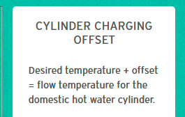
No, AFAICS the only other thing is the max compressor current, for the 12kW the normal limit is 25A and I have turned mine down to the minimum setting of 20A so there is hopefully some capacity in my 4.4kVA battery inverter for other stuff. You might have in mind this one https://www.youtube.com/watch?v=tAoRH_WEt78. At 4'45" Adam is under the same misapprehension as I was, that Vaillant's target DHW plus their offset (he calls it "differential") is the actual flow temp. But as I have discovered in the last 48 hours it is nothing of the kind, it is a minimum. The reason he gets a much better CoP than I do (>4 vs 2) is that he has a small HP and a big coil, I have the opposite. The HP set to 50 with zero offset is producing hotter water than the immersion did set to 55 (which was more than adequate). Maybe something to do with relative positions of heat source and sensors, also I have now added a de-stratification pump. I will revert to the immersion tomorrow and see what temp the HP thinks the tank is, to cross-calibrate. Then will turn down the HP setting to match, bearing in mind legionella (which we have not knowingly had any problem with).
-
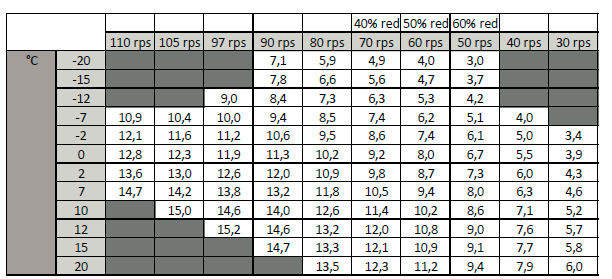
Do you have more details? From the manual there are Eco mode: "Compressor output control that is as efficient as possible (longer cylinder charging time)" Normal mode: "Balanced control [!] (short cylinder charging time/maximum compressor output)" Balance: "Rapid charging for a cooled cylinder in combination with efficient re-charging by controlling the compressor speed" [IIRC it also says somewhere that Balance uses max compressor up to a certain tank temp then Eco for the rest] So one of the first things I did was to select Eco mode. But as upthread, at summertime OAT this gives 9kW thermal output, which is too much and gives un-necessarily high flow temps and correspondingly low CoPs. It makes more sense for the small HPs, but the 12kW ought IMO to be capable of being turned down a lot further. There is also an independent Noise Reduction mode which sets a maximum of 45.4% compressor speed, so the same (they are not compounded!). Bingo!
-
Yes, thank you for your help over many months and I am only sorry you are still enmeshed in the noise dispute with yr LAPD. Have been experimenting with the vexed small HW coil a bit now. You might think that this statement defines the actual flow temp but it doesn't. It appears to set a minimum. It seems the Vaillant HW strategy is to push energy into the tank as hard and fast as poss, which is resulting in flow temps of over 70C.This makes sense in the winter when you want the CH to have the min downtime. In summer it means the HP works unnecessarily hard and you do not get the optimal CoP. The Eco setting gives 45.4% compressor mod. But from the Czech performance tables this still means at today's OAT there is 9kW min thermal o/p to be dissipated somehow. Eventually when tank reaches 48C it turns down to 40.8%, and it ends up at 36.3%. It would be nice to have had that option from the start. Or 27.2% which is the min mod level it can and does achieve for CH. Charging both HW cyl and TS in parallel this morning maintained the nominal flow rate of >2000 l/hr and resulted in somewhat better behaviour, but the final outcome was still 5.15kWh electrical input to top up tank after two showers, which is about the same as using the immersion heater. As it tells me I am achieving a CoP of >2.0 this means there is another 5kWh thermal going somewhere which I can't account for, other than the standing losses for the thermal store which themselves are 1.49kWh/day. So I may just save the wear and tear on the HP and go back to using the solar diverter + immersion during the summer. Advantage is that it will adapt to whatever free PV is available whereas the HP will take what power it wants, from battery if necessary. A dummy anti-legionnaires cycle once a week should keep it from seizing up. Still some other things to try and some snagging to get them back for.
-
Compared with a heat pump there is virtually nothing to go wrong with MVHR so a bizarre objection. IIRC there is no proper way of accounting for it in MCS calcs, my installer reduced the target room temps to 18C throughout as a rough correction for it.
-
Your timing is perfect as this morning I tested the behaviour of the HP starting with all the rad valves fully open. Have started a new thread here.
-
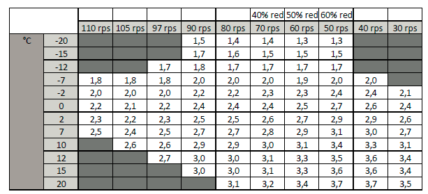
Finally got my new HP installation up and running last Friday. Some issues on the DHW side which I will write up in due course but this morning I tested the behaviour of the radiator circuits starting with all the rad valves fully open. OAT 21.5C. Target flow temp 47.5C, actual 49 - 50C (but see below). 11 rads in circuit: Flow rate 1670 l/h (nominal/max is 2040). Power input 4.0 kW. Compressor modulation 75.5%. No flow through automatic bypass. Some tonality in the noise from the outdoor unit. 7 rads: Flow still 1651 l/h. Power input 3.0 kW. Compressor modulation 53.1%. No flow through automatic bypass. No tonality any more. 2 rads: Flow now 1333 l/h. Power input 1.6 kW. Compressor modulation 27.2%. Some flow through automatic bypass. 1 rad: Flow still 1400 l/h. Power input 1.4 kW. Compressor modulation 27.2%. Some flow through automatic bypass. Actual flow temp on VWZ AI Appliance Interface is 50.5C but on the VR720 SensoComfort controller only 42C. Both use the same single sensor. 0 rads: Honeywell wireless TRV system no longer calls for heat, HP shuts down. Conclusion: the system is well behaved. Interface with legacy Honeywell control is operating correctly, it will mainly be used to zone off unused rooms depending on occupancy. Normal operation will rely on the WC in the HP. There is also underfloor heating to most of the ground floor which will provide an additional base heating load. Dynamic range of modulation is 2.8 to 1 in summer temperatures which is quite good, it gets better as OAT falls as per the chart below. (Max compressor current is turned down from 25A to 20 to match output limit of Victron battery inverter in EPS mode. However output is limited ATM by the OAT of 21.5C): CoP varies a bit with output but reaches 3.7 at current OAT
-
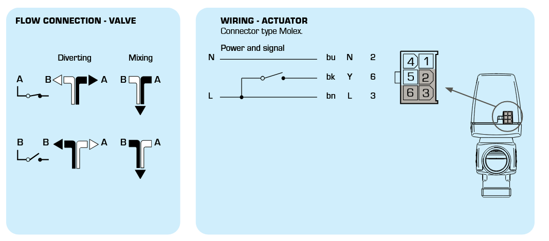
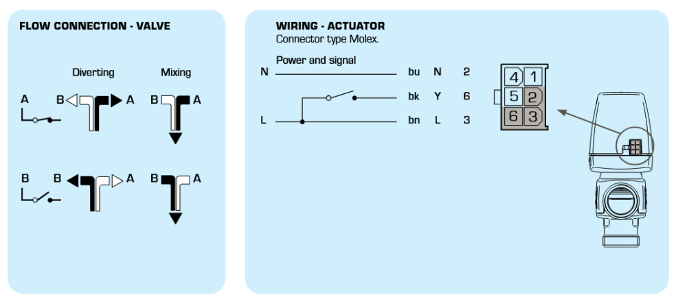
Esbe type VZC and VZD diverter valves have this wiring: So Auf to black and neutral to blue. I read this diagram as energise for Port A (DHW). The permanent live to brown powers the anti-seize function once a week.
-
Default Vaillant config is as shown, for a spring return valve e.g. Honeywell 4044. Auf (open) energises valve for DHW (port A), spring return for heating (port B). Zu (closed) terminal presumably for valves that require power to move in either direction. Don't know the wiring for ESBE valves unfortunately, what does the leaflet say?