Pete
-
Posts
1093 -
Joined
-
Last visited
-
Days Won
2
Everything posted by Pete
-
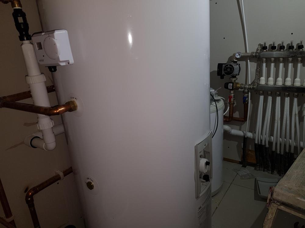
I have a gauge on the inlet manifold reading about 19 degrees and it is warmer than the return but I would have thought it would be warmer than this? I have just turned the water temp setting on the ashp to 20 degrees to see what that does as at 45 degrees was causing defrosting issues
-
we turned it up to 45 degrees to see if we could get some improvement on the floor temp so should we turn it back down again?
-
Thought so but it keeps defrosting so is that right as completely in the dark regarding this system?
-
Finally got the heat pump up and running. After clearing the air locks the system seems ok (?) but just need some reassurance that it is working. The house is obviously very cold (10 degrees) so it is going to take some time to warm up. How long does it take to see some improvement as it went up 1/2 degrees but I also turned on my mvhr today so a few things changed? What have people set the water temp for the ufh? House size is approx 26 x 9 internal floor area and is all ufh on a Passive slab so I know it is going to take a while. When I initially got it running the buffer tank heated up quickly but the blending valve was not adjusted so as soon as i altered that the heated water went into the ufh pipes and all the heat just dissipated so I guess I am after as much info regarding the first time of turning on the ufh and the running of there after, please!! I know you have to warm the slab up slowly but it could'nt get any slower but I am comparing it to rads as I have never experienced wet ufh before. TIA
-
I have used my Sigma tile cutter to cut 1.2m tiles and it worked great, even producing neat edges on cuts up against sliding doors that will be seen
-
I made my own using a Bosch plunge saw and it worked really well. I needed a certain height due my shadow gap skirtings and struggled to get the right size so made my own as well as the door casings
-
Did you get chance to view the info from Secon @PeterW?
-
Secon Panasonic H Series rev1.3.pdf
-
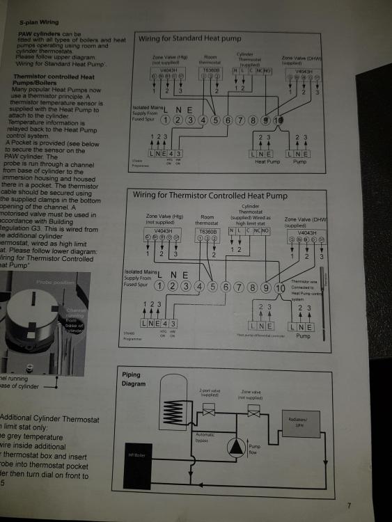
That is the wiring diagram that Secon sent. Secon provided the tank, heat pump,diverter valve and buffer tank. Wunda for ufh and thermostat for the room is just a generic stat. Will they and get the secon document for you now
-
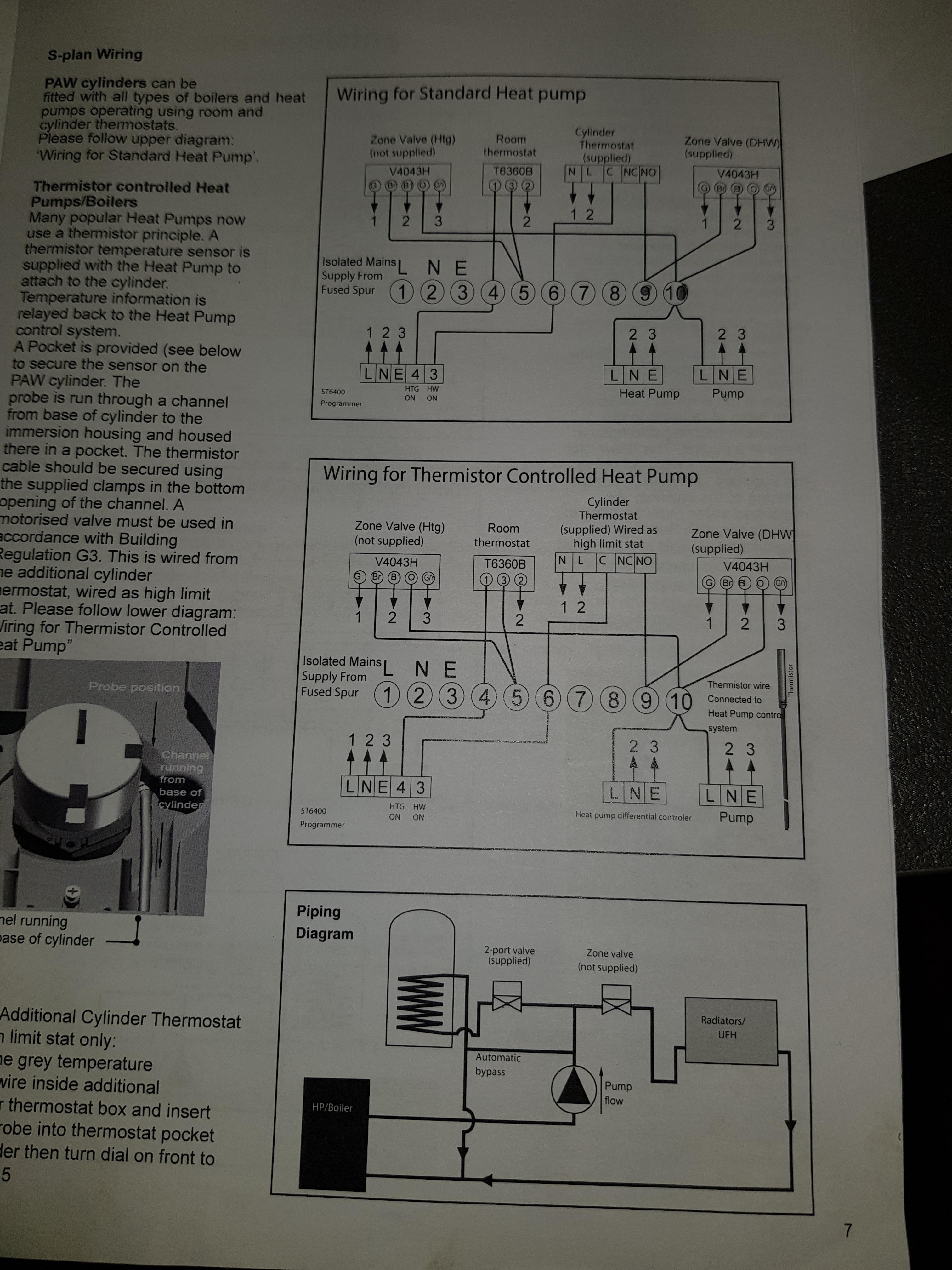
If you go to the bottom of the first page you will see two wiring drawings. The top one with the ufh wired into the base station is the Secom method and the other one is the Panasonic way
-
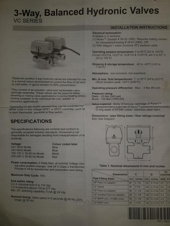
Valve is 240v, it says on it. It is a VC6013 Honeywell. Yes second provided as a kit. Yes there is a buffer tank.
-
This one
-
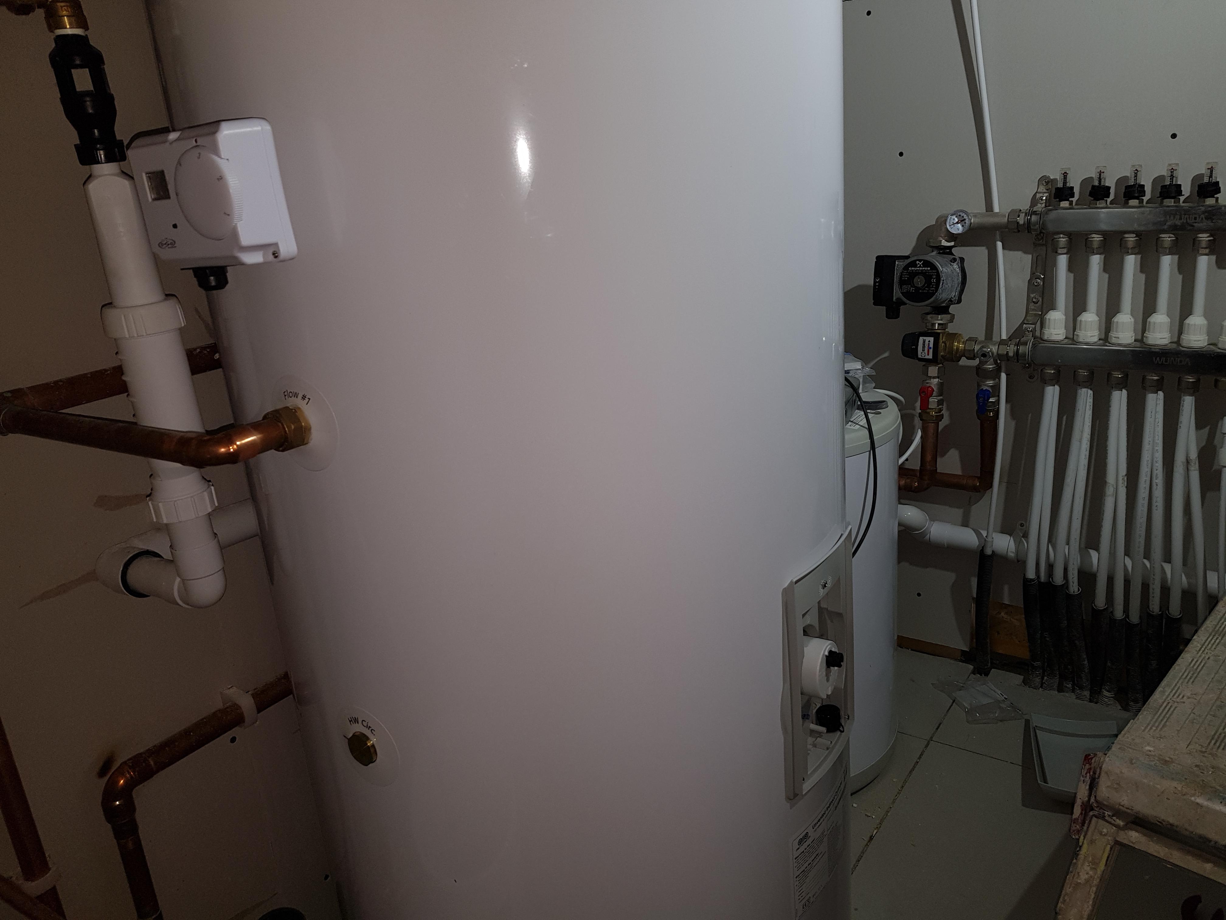
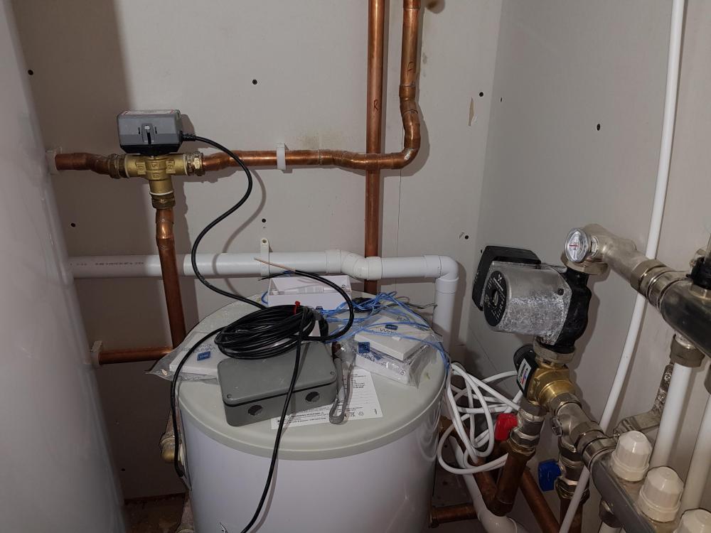
But the lower diagram is not my setup. My flow from the HP goes to a diverter valve and then either UFH or HW. Normal op is to go to UFH and then when heat is called for HW the valve operates to change the flow.
-
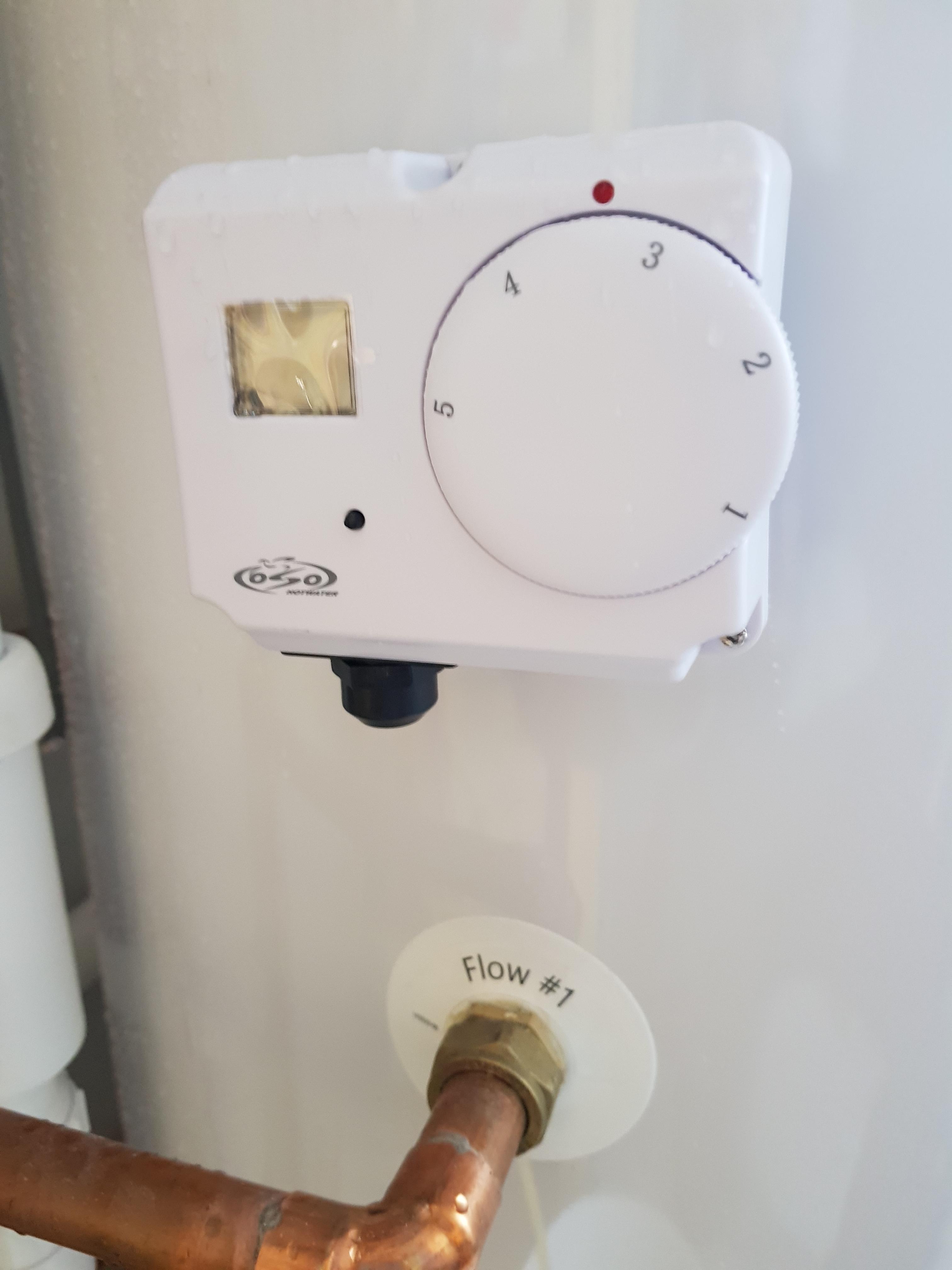
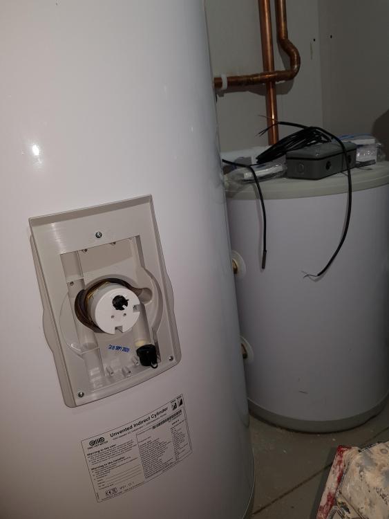
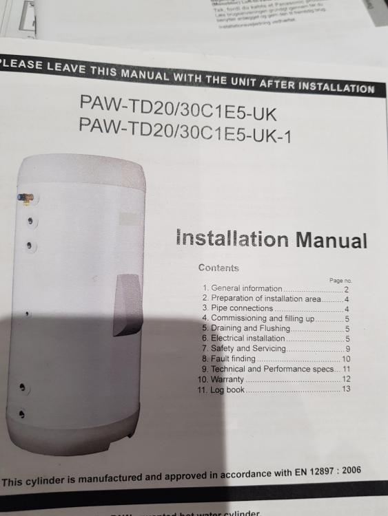
If you look at the picture of the cylinder there is a grey cover halfway down RH side. Under this cover is the electrical connection to the immersion and the tank sensor connection which is a complete stand alone cable. This cable consists of a two core cable with a metal torpedo which I assume is the sensor so this cable is not connected to the sensor with the rotational wheel
-
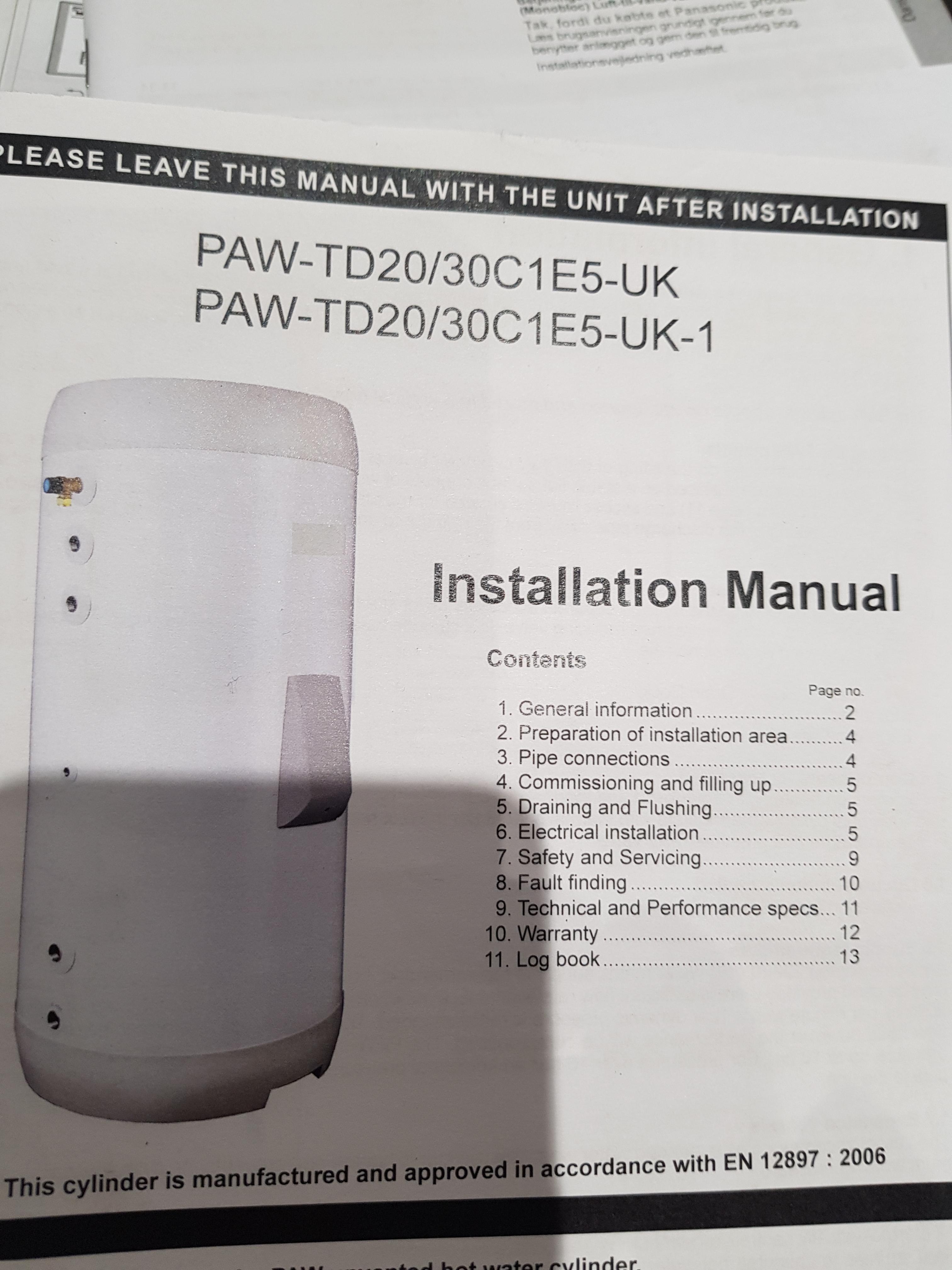
It's a matching Panasonic cylinder and heat pump so nothing wrong it is just wiring it up to work efficiently. When I look inside the inst booklet it includes these wiring diagrams but as I have already said the heat pump guy (Seconrenewables) has said to wire it up like the one in the other drawings I have sent which shows the ufh circ pump being wired into the room stat base station..
-
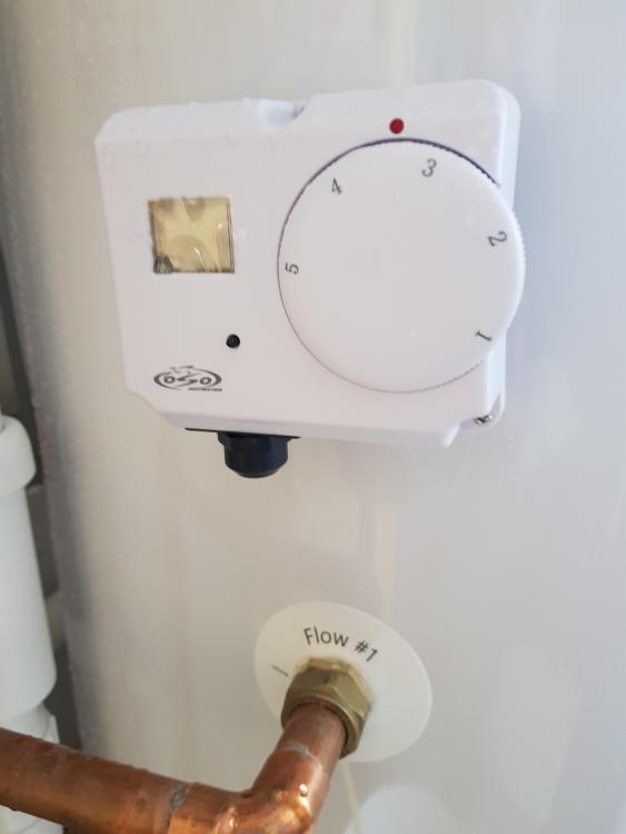
No but when you open it up there is a circuit board where incoming wires should be connected to and two smaller wired are connected to the circuit board and disappear behind the insulation round the tank Dont think so as there is nowhere for the batteries and there is a gland for cable access
-
The Panasonic controller looks like it does everything. Trouble is the heat pump supplier is telling me one thing and Panasonic another so hence the confusion from my point of view
-
Thanks Peter. No it is not a pre plumbed cylinder but in the two wiring diagrams it is not mentioned as far as I can see. There is a separate tank stat that ( 2 wire cable with torpedo on the end that fits into a pocket and this goes back to the Panasonic controller) so not sure where/how or why this fits in to the system
-
This little rascal!!
-
How would you wire it @PeterW? Many thanks
-
No insertion pockets and it is foamed. Which picture are you referring to as there are two? The diagram of the circ pump wired from the heat pump is what Panasonic are advising. The other drawing ( where the circ pump is triggered by the thermostat)has come from heat pump supplier and he is recommending to wire it up this way. At the moment I am going round in circles as the advise is so conflicting so I put it on here and it changes again. At the end of the day I just need a working system for a Passive house that I can just forget about. My sparky mate was meant to be coming over from France to get me connected but even that looks dodgy at the moment (but he is old school with vast experience of older type systems) so any advise without turning everything upside down would be beneficial. Also non of the diagrams include how the tank/immersion stat on the side of the HW tank is incorporated into the design? As I understand it the stat is wired from the heat pump and is 230v ( I think)
-
I am currently going round in circles trying to get our house ready to move into and keep on getting conflicting advice. I have received more info today from the heat pump supplier and the wiring diagram is different to the original one. Whilst I know there are numerous ways to wire heating systems I am getting so confused as to which way to go. The heat pump guy suggests the best way to go is to let the heat pump run the buffer tank and that is the easiest way to do it but my sparky mate is proper old school and is not so sure of what is the best way other than a traditional room thermostat. The Panasonic controller is a real fancy bit of kit and can seem to do most things but the two wiring diagrams I have received from the supplier differ slightly. Plus how can the heat pump control the buffer tank as the buffer tank has no sensor, it is purely a buffer tank with no coil etc?? Please see drawings as you can see that the circ pump (ufh) and thermostat wiring is different so not sure what is the best way forward? TIA ASHP Drawing.docx
-
Sealing and repairing where uPVC window frames meet mortar (external)
Pete replied to Oxbow16's topic in Windows & Glazing
I used Ct1 to seal some of my exterior windows to the Parex render and quite a few have cracked at the sill/ reveal junction so I think it is not flexible enough? My frames are aluclad and get full sun in summer so I expect the exp/cont of the sill is the problem. Bought some silkaflex and going see how that goes -
Just a tip. Have you decided on your switches as it can make a massive difference to your wiring? Only reason I am telling you is we wired traditionally as we had not decided on switches at this point. FF a couple of years and we decided to go with I lumos switches and they use a lot less wires so you can save quite a bit on sparky time. What I would say is the I lumos look lovely and when they work they are great but it is a steep learning curve wiring these switches but that is another story!!
-
Yes, 600 centres on vertical battens fixed into the structural part of the t/frame. The boards are called Moisture Resistant Boards which the Parex render was adhered to.