
MikeSharp01
-
Posts
5667 -
Joined
-
Last visited
-
Days Won
16
Everything posted by MikeSharp01
-
 I assumed - it's a timber frame and so it seemed like a good idea, I guess I should read up and see what's what. I have it all done in fireline board so it feels wrong to fit a bare plastic back boxes although I guess you could assume the fascia will do the job?
 -
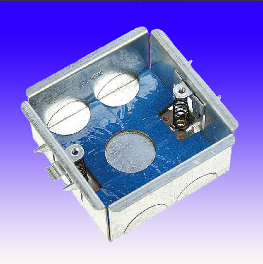
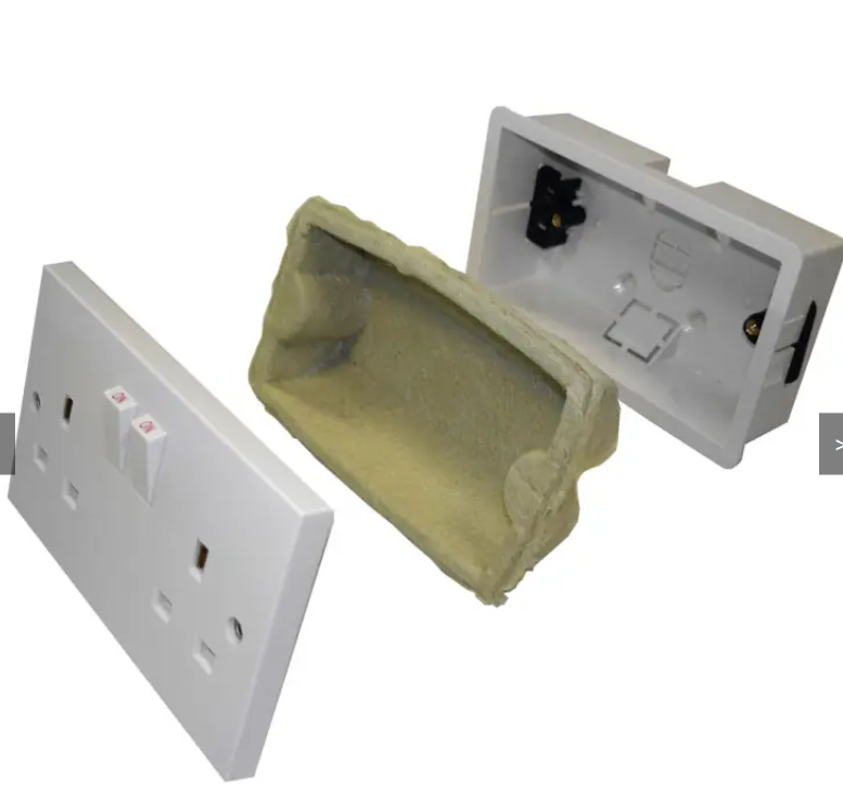
I am getting very frustrated with the Scholmore metal dry lining back boxes. They look great in the blurb but I have either got a bad batch or something is fundamentally wrong with the design. They are difficult to fit as the spring mechanism that holds lugs is almost always dysfunctional, slides out of its guide at the bottom & tilts over so takes a lot of fiddling to get it to grip and fitting the face plate involves even more fiddling. Maybe I am missing something but I cannot see what. So I am looking for alternative solutions to fire protection in drywall back boxes. I have found these inserts: From Astroflame which look can work with both plastic and metal back boxes so I can use the standard plastic back boxes and fit these things although, to be honest, they also look a bit clunky - does anyone have an experience of these inserts or perhaps a better solution all round to the problem.

-
How to unlock unlimited geothermal energy, anywhere we want
MikeSharp01 replied to SteamyTea's topic in Boffin's Corner
While this is exciting stuff and I applaud the work being done I have not seen the counterveiling discussion around moving energy from the core to the surface and the consequences there of. If we cool the core what are the consequences? As I said this is exciting stuff but we should have learned by now that our use of planetary resources has consequences and geothermal energy may not be a 'renewable' resource. -
We have the AFT raft system and very good it is as was the service we received - shame all round.
-
Is nuclear power really green?
MikeSharp01 replied to saveasteading's topic in Environmental Building Politics
People get confused about small nuclear and tend to say "they have them in nuclear submarines so why not take that technology and pop it into ships" - sounds like a fair plan until you realise that the fuel for these subs is weapons grade (95% enriched) to reduce / remove refuelling demands to 30 years plus - refuelling less highly enriched 10-20% is very complex and expensive needing specialist facilities. We have limitations treaties on the fuel so that's a limiting factor as well. Also many countries do not allow nuclear powered ships to dock for safety reasons, you need greater security for the ship when travelling and much better trained crews. -
Sounds like your system is open to the main sewer, have you got a dry trap somewhere - washing machine for instance or maybe an air admittance valve (AAV) is stuck and your loo flushes are sucking a trap dry.
-
Seems rather crude just to screw into a casing, might be more robustly done with rivnuts or some such.
-
Do you run your systems automatically, manually or semi manually. I guess I can see how you could 'mess up' in manual mode but how might you 'mess up' in the other two?
-
Pretty much sums it up! So are all the walls in your place interactive so you can live in this psychedelic paradise you have prompted into existance- reminds me a bit of a scene from the Ipcress file - @SteamyTea will no doubt find it and add it to this thread.
-
No, well that might be where the rest of us are. Here is my summary: You started with using local LLMs to develop some automation, tried to recreate 'Alexa' or some such and had some success doing it but you got taken over by the need swell your memory so you handle even more billions of weights etc then got involved in multi modal stuff and games development and now you are lost up the Orinoco without any memory of the journey or the objective - so essentially without a paddle!
-
Seems to me that you are so far off Piste that you have taken to asking Claude to create new Pistes for you to play in. Just give us a catchup on what you are are actually trying to achieve so we can get some context without pasting all 17 pages into Claud only to have it tell us that its been working on this with you but it has no clue where it might all end up.
-
Europe’s heatwave is the hottest and most humid ever
MikeSharp01 replied to SteamyTea's topic in Boffin's Corner
We perhaps need to find some common ground here so we can identify the aspects we can agree on and then discuss the things we don't - this is usually (still) a good basis for discourse and otherwise we are contributing to the death of nuance and increasing polarisation which gets us nowhere. All it does is improve our ability to throw language laden bricks into the opposing camp. So to kick this off perhaps: Can we agree that the planet is warming up whatever the cause? If we are able to agree at least that we can perhaps then discuss consequences, mitigation strategies and opportunities it brings. Only after that we can discuss evidence for causal factors, natural cycles, human activity, adjustments by the operators of the simulation we are all living in - the science, or otherwise, of what is happening. -
Europe’s heatwave is the hottest and most humid ever
MikeSharp01 replied to SteamyTea's topic in Boffin's Corner
If you think it through the answer must be that it does not. If you watch a toddler you can see the principle at work - they are happy operationalise, they understand it, although they perhaps cannot explain it. It only takes an inspirational teacher in a school to expolain it and suddenly its clear what the method is. Make an Observation: Identify an event or ask a question about the natural world that requires an explanation. (Can I climb this hill thing [stair]?) Form a Hypothesis: Propose a testable, educated guess or plausible answer to your question. (Let's see) Conduct an Experiment: Design a controlled test to see if the hypothesis holds true under specific conditions. (One step , crawl climb of whatever) Analyse the Data: Examine the results gathered from the experiment to determine patterns or trends. (Yep I am at the top / nope I have hit something that stops me - the stair gate!) Draw a Conclusion: Decide whether the evidence supports or rejects the hypothesis. If rejected, the hypothesis is modified and the process restarts. (I can climb / I need to modify my approach and try when the stair gate has been left open.) To operationalise it in any field of advanced research does need a lot more education and experience - that I agree, but not the scientific method itself - that is child's play! -
Bonus edition - Garden landscaping
MikeSharp01 commented on Benpointer's blog entry in Contemporary build in north Dorset
Wow - that's some landscaping - its been so long since one has seen so many terraces in a design- looks great and once it has grown in it will look amazing. Until the epilogue then.....- 11 comments
-
- 1
-

-
- landscaping
- garden
- (and 2 more)
-
How tall do you need to be to operate those switches.
-
Dialogue is always a good approach and one thing this place has taught me is that there are often ideas out there that have not hit your consciousness and this thread is an example. It has saved me about £200 in 6mm cable and a lot of working pulling cables through ducts and along trays - so its a win for me. I do need to build a bit of infrastructure to mount the switches but otherwise its a winner. Thanks all.
-
I could put them in the cupboard below the ovens - the one above would be too high up, would that work? The hob is on the island along with the kitchen ring.
-
The 'interior designer' has persuaded me to locate the isolators for the ovens on the kitchen island so they do not break up the aesthetic of the oven wall. These would be 1.4m from the Ovens across the gangway from the wall with the ovens. Each oven has a max draw of 3600W so 7.2kW with both on full power. Each of the two ovens will have there own 32A isolator in the Consumer Unit (CU), To achieve the run it ends up as a lot of 6mm cable: CU - Island (12m) & Island - Oven (15m) I am going to have 27m run (Voltage drop 3.5V approx), none in insulation but in duct and trunking. [I would need only 5m of 6mm cable if the switches were local to the ovens] So for these two ovens I will need just over 50m of cable which in itself is not a problem but I thought I would get a sanity check here to be sure I am not breaking any rules doing this - it looks OK to me regs wise. Any thoughts - should I push back on the interior designer?
-
If your contractor has set up a water supply for the site from your connection point, assume its a water meter but it may just be a stop cock, then they can do all the other work without the water company being involved - they just need to follow the regs eg double non return valves etc.
-
I am aware that some manufacturers have had issues with condensation in the walls of their machines it may just be that. Why not look at a dry the panels out solution - drill a pluggable hole, connect a pipe to the hole and a tub of silica gel and see how much moisture you can draw out that way. You can get Silica Gel in volume: https://www.amazon.co.uk/Quart-Replacement-Desiccant-Indicating-Silica/dp/B013L31PQ0 that one is indicating - it changes colour as it gets wet and is likely to be toxic if swallowed - IIRC normal, non indicating, silica gel is harmless though
-
'Where We Live' - a survey of the decline in British housing.
MikeSharp01 replied to MAB's topic in Housing Politics
Utilitarianism has some fundamental downsides I think such as how do you assess greater good anyway. It it how all the people see it or just a few who say "this will be for the greater good" alternatively is it for the greater good now or later - hard to know! -
Well I had a play today with my old surface pro - it has a GTX 1060 GPU with 6Gb of RAM, its about 9 years old! I thought can I get Gemma4 4b into that and drawing. SO I gave it a try and after some messing about I ended up with this - some HTML code output at about 25 tokens / second. Using an un-quantised Gemma4 4b model - not bad I thought without any flooding into CPU memory.

-
'Where We Live' - a survey of the decline in British housing.
MikeSharp01 replied to MAB's topic in Housing Politics
They could have solved this with education - if everybody thought about the environment, their fuel bills, comfort etc - all those things would happen naturally. In essence you either have the ideological state apparatus or the repressive state apparatus you can avoid either with the other. -
'Where We Live' - a survey of the decline in British housing.
MikeSharp01 replied to MAB's topic in Housing Politics
My analysis is a bit different - planning is a part of it but the bigger part is developers interests and councils not being allowed to build council housing. The former is a problem because they want to keep prices high and maximise profit so they have no interest in mass production as it rises the supply side and so reduces prices. The councils not building for social rent, I get that housing associations are supposed to do this but funding constraints meam means that they are actually just developers, is a problem because it forces private rental and that removes housing stock from purchasers and so pushes up prices - which just closes the loop again. So sorting planning needs much more out of the box thinking alongside it. -
Shower tray, waste rough?
MikeSharp01 replied to Super_Paulie's topic in Bathrooms, Ensuites & Wetrooms
I smoothed our daughters tray underside, which was awful, with isopon and a piece of plate glass, dead flat, to ensure we had a perfectly flat surface to mate with the trap, seems to have worked - all done dry- no ct1 and no leaks 4 years on.