Jeremy Harris
-
Posts
26430 -
Joined
-
Last visited
-
Days Won
360
Everything posted by Jeremy Harris
-

Anyone know how much sway Parish Council has?
Jeremy Harris replied to nubbins's topic in Planning Permission
Great News! Just at the right time of the year, too. -
Another option to consider if you are looking at using a low grade heating system, like under floor heating, is a hybrid ASHP, such as the Daikin Altherma Hybrid: https://www.daikin.co.uk/en_gb/product-group/hybrid-heat-pump.html . These combine an ASHP to give low temperature water, (so the efficiency is pretty much always very high) and then boost that temperature to usable hot water temperatures using a small built in gas combi boiler. The result is that the heat pump always works with a high COP (coefficient of performance) and the amount of gas used is decreased because the water is preheated. The downside is that they can be costly, and there is no provision for making use of excess electricity from solar panel generation, if you are looking at fitting them. You could add a Sunamp PV to such a set up, but the costs are beginning to stack up, and you may well be better off with a straightforward Sunamp PV and gas combi system.
-
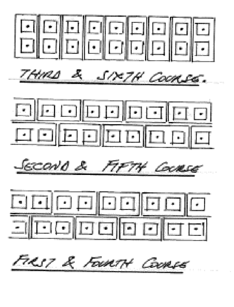
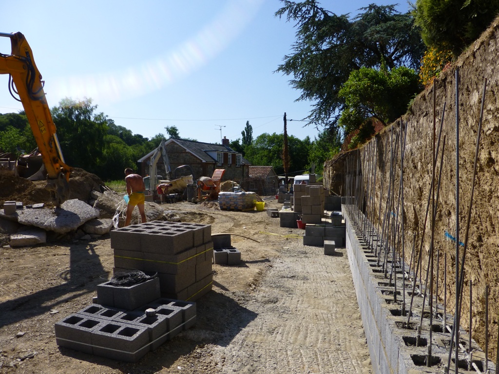
Thanks. perhaps that's why the SE went to the trouble of doing that little handwritten sketch on the drawings, to make sure that the guys built it as he intended! I can see how it works, with the two courses staggered and then the course of headers tying the front and back sections together. Somehow I don't think it will fall down, especially as the vertical steels project around 700mm down into the footings...................
-
Welcome. Yes, at the moment if you have gas, then use it. The problem with all heat pumps (excepting hybrids) is that they don't give great efficiency when heating hot water. The RHI is also a nightmare, as to claim it you been to jump through a lot of hoops, including using a certified installer, and the certified installers charge WAY more to install the kit because they know you're claiming the RHI......... If you opt to use a gas combi boiler, then you can also use energy stored from the excess from a solar panel array, using a Sunamp PV. This effectively fits ahead of your combi for hot water and either means your combi doesn't have to run at all (perhaps in summer) or that it runs less at other times, using preheated water from the Sunamp PV. It's a good compromise, as it allows the use of gas to get decent hot water temperatures, yet reduces gas use by utilising excess electricity generated from solar panels.
-
This is the note on the SEs details, which makes it seem a bit more complicated than that:

-
The closest I've found to a RPi, in terms of price and performance, but including a SATA port, is the Banana Pi, or the Banana Pi M2 if you want a SATA port and WiFi/BT, like the RPi3, To all intents and purposes the Banana Pi is about the closest any of the cheaper SBCs come to emulating the RPi, and will run Raspbian, if that's your preferred flavour of OS. Still no RTC, though, but adding one via I2C is as easy as it is on a RPi, or you can just use a time server if the unit happens to have an internet connection. TBH, just having a SATA port makes the world of difference, as it means getting away from having to boot from an SD card, or via a slow USB 2.0 interface, and allows better control of the filing system. At £32 inc VAT for the Banana Pi, or £35 inc VAT for the Banana Pi M2, there isn't much of a price difference with the RPi 3 either. The main snag is that the board is physically a different size, so won't fit in cases designed for the RPi.
-
I used modular, rather than grid, frames to get mix and match satellite/phone/ethernet connections - for example I used double gang four module plates with four ethernet modules as a neater way of terminating all the ethernet cables in my study, where the router, switch etc is housed, rather than an industrial looking patch panel. The problem you have is the same one I had where I needed a multiplexer to get the DAB/FM signals down. I ended up biting the bullet and splashing out for a media plate. This has four switched power outlets, two satellite sockets, FM and DAB (multiplexed), a phone socket plus four spare module slots, that I used to feed wall speakers. The unit I used was the MK Logic one: http://www.gil-lec.co.uk/mk-logic-k2740-4-gang-combination-plate The annoying things were the cost of the back box, plus I also had to splash out on a multiplexer box to fit at the other end, where the antenna cables come into the house.
-
Yes, and out the back, too............ The footings are 2000mm wide by 400mm deep, plus a 360mm wide x 400mm deep key on the bottom of it, under the wall section, so the footings are actually 800mm deep reinforced concrete (C35) under the wall itself. 1350mm of the 400mm thick reinforced concrete footing projects out the front of the wall............. The second page of the SE's sketch below shows the wall construction detail: 20130228093748130.pdf
-
Conceptual and detail design software
Jeremy Harris replied to LouiseSJPP's topic in New House & Self Build Design
AutoCad is a bit like Marmite, you either love it or loathe it...................... I had Solidworks for a time, and even though it's really powerful, I found it extremely difficult to use, due entirely to me having around 30 odd years worth of AutoCad experience. Others i've spoken to have said that getting to grips with Solidworks is a LOT easier than getting to grips with AutoCad, and they are probably right, it depends very much on your past experience I think. -
Out of interest, is this header bond? It was alternate rows laid with one row with the blocks aligned along the axis of the wall (two blocks thick) and then the next row aligned across the wall, so the ends were facing out. The lower part of our big retaining wall was laid like this, with rebar up through the holes (that were later concrete filled) and also rebar laid across the horizontal joints. The guys building it reckoned that the SE had gone a bit OTT, especially given the size of the reinforced concrete foundation.

-
Vaillant ecotec 938 heating resume delay faultby 2 minutes
Jeremy Harris replied to shab's topic in Boilers & Hot Water Tanks
Not sure this is much help, but we have a smaller Vaillant Ecotec Plus 831 and there is always a delay when switching from hot water to heating. On ours, I've watched what the boiler does, and the sequence goes like this. - Open a hot tap, even for a few seconds, and the boiler shuts down if actively heating, and starts the process of switching to hot water mode. - The diverter valve then operates, to switch the boiler into hot water mode and this takes a few seconds for the valve to motor to the new position. - The boiler then runs through the hot water start up sequence, with the fan starting, the pump starting and when the pump kick is detected the igniter fires and the gas valve is opened. The boiler then checks that the flame is present and if so modulates the gas valve to provide the set hot water temperature. This process takes maybe 10 to 20 seconds or so. - Close the hot tap and the boiler senses the flow reduction in a couple of seconds and shuts down the burner, keeping the fan on to clear the burner chamber for a few seconds. The diverter valve then rotates back to the heating position and the boiler runs though the heating start cycle. If the boiler is hot (i.e. if it had been running in heating mode when there was a hot water demand) then it will often go into the anti-short cycle delay, with the pump over-run timer on to cool the primary circuit down a bit. - At the end of the pump over-run delay if there is still a call for heat from the thermostat the boiler will run through the start sequence, the fan will come on, the pump will come on, the pressure sensor will detect the pump kick and start the ignitor and then open the gas valve. Once the flame has been detected, the gas valve will be modulated to deliver the set heating flow temperature. None of these things happen instantly, and each operation takes a few seconds. If the boiler has heat-soaked during hot water delivery then there is a very high probability that it will go into over-run mode and there will be a short delay with water circulating through the heating circuit until the burner start up sequence starts. This is pretty normal behaviour. If you want to check what your boiler is doing there should be a way to look at the first level diagnostic codes on the display. On ours, pressing the "i" button brings up this display, and with the benefit of the table in the back of the manual you should be able to see what mode the boiler is in, i.e., whether there is a call for heat, whether it is in over-run mode or whether the burner is operating. The symbols on the display may help too. Ours displays a flashing radiator symbol when there is a call for heat but the boiler is on the over-run timer, a solid radiator symbol when there is a call for heat and the boiler is not in over-run mode and a flame symbol when the burner is operating. The first level diagnostic codes just give a bit more detail as to what is going on. -
Not at all, there is a very long history to this forum, that dates back at least 12 years or more. It had a predecessor, that sadly was closed down, and 14 of the regulars there decided to resurrect it. As a bit of a joke, we carried over the post counts from this forums predecessor to here, so you can spot the founder members by their post counts, in the main. I wouldn't pay any attention to the number of posts, it's the quality and usefulness that is important, and that is outwith the control of the person posting. There is a "leader board" that shows who's made the most recommended posts in any day, week month or whatever, but the most important thing is to form your own view as to how much help anyone gives, or more importantly, the community here as a whole gives. We try to be as leaderless as possible, and let the forum members all have an equal say, and treat all as having an equal standing, whether they've been here for ages or just joined. I do think we'll b challenged a bit to give useful advice for your location, but you can be damned sure we'll tru our best!
-
2017 What worked and what didn't
Jeremy Harris replied to SteamyTea's topic in General Self Build & DIY Discussion
Ours is the Genvex Premium 1L, slightly over-sized for our house, we could have used a Premium 1, but the additional cost for the 1L was small, and the additional capacity is useful. Here's a link to the Danish supplier we bought ours from: http://www.sundthus.dk/genvex-ge-premium-1l-hoejre/ -
2017 What worked and what didn't
Jeremy Harris replied to SteamyTea's topic in General Self Build & DIY Discussion
Essentially it's just a normal MVHR unit with a reversible air-to-air heat pump built in, so it can add around 1.5 kW of heat to the fresh air distributed around the house or remove around the same amount of heat by pumping cool air into the fresh air distributed around the house. The main advantage is that it's a "single box" solution, that is installed in exactly the same way as an MVHR unit, with no additional ducting, plumbing or wiring connections. The main disadvantage is that it is really just a comfort cooling unit, or heating for a house with a low heating demand (it would happily keep our house warm in winter on it's own), and isn;t well suited to use in houses that are less well insulated or airtight. -
2017 What worked and what didn't
Jeremy Harris replied to SteamyTea's topic in General Self Build & DIY Discussion
Yes, it's 300mm of cellulose in the walls and 400mm of it in the roof. Rather than the Genvex, if you have a source of cool water (say, from a heat pump) then you can just fit a duct heat exchanger, one of the ones with a condensate tray. It would probably work just as well, and with hindsight that may well have worked well for us and been cheaper than the Genvex by a fair bit. However, we did buy the Genvex direct from Denmark, so the true cost was not far off half the cost the UK supplier wanted. In hot weather, it does definitely help to keep the bedrooms cool, and for us that makes it worthwhile. -
2017 What worked and what didn't
Jeremy Harris replied to SteamyTea's topic in General Self Build & DIY Discussion
Didn't work: 1. Complicated heating controls, after many months of playing with weather compensation, controlling the house temperature using the floor slab temperature and assuming that the logical link between floor temperature and house temperature would work well at controlling the latter using the former, I realised that, as the heating system only provides a small part of the total house heating, it would never work, so I gave up and installed a very simple room thermostat, which works very well. Should have done this in the first place. 2. Water filled thermal store. No matter how much extra insulation I added around it, the heat losses from it were still very high, over 2 kWh per day (as supplied, with a double layer of insulation, the losses were over 3 kWh/day). This cause the services room to get up to around 40 deg C in summer, damaged the oak door between it and the bedroom and caused the adjacent bedroom to badly over heat. Swapping the thermal store for a Sunamp PV, with it's massively lower heat losses, completely fixed the problem, and freed up lots of room in the services area, too. 3. Complicated ozone injection and flow rate control system on the borehole feed. It worked, but was far too complex and has now been replaced with a much easier to service, very simple eductor, that is far more effective at adding and mixing ozone to the incoming supply and also easier to service and repair. The brass eductor took two goes to get right, but has no parts to wear out, no flexible seals and should last forever. Did work: 1. Choosing an insulation system with a high decrement delay factor. Not only does it significantly improve the comfort level in the house, by helping to keep the internal temperature steady, but it has the added bonus of being an extremely good acoustic insulating material too, so improves the soundproofing and deadens the internal acoustics a fair bit (handy in a house with a lot of hard surfaces). 2. Opting to have UFH inside the insulated concrete slab. This forms a nice big "storage heater", yet responds pretty quickly when needed. Having a heated (or cooled) power floated slab that was flat and smooth enough to lay flooring to directly saved a lot of hassle and money. 3. Choosing the more expensive Genvex MVHR with the internal air-to-air heat pump. It's not massively effective, but does do a pretty good job at keeping the bedrooms a degree or two cooler than downstairs in very hot weather. It also does a great job of drying out towels or washing left on the drying rack in the utility room. 4. Avoiding the use of highly paid consultants etc whenever possible. I found that, with a bit of effort, I didn't need to use many at all. It seems that when you are self-building a house every Tom, Dick and Harry comes at you with their hand held out for more of your hard-earned cash - you can avoid paying out a lot of this with a bit of determination and time. -
Welcome from so far away!
-
Conceptual and detail design software
Jeremy Harris replied to LouiseSJPP's topic in New House & Self Build Design
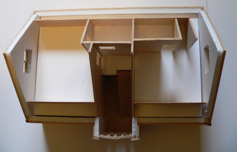
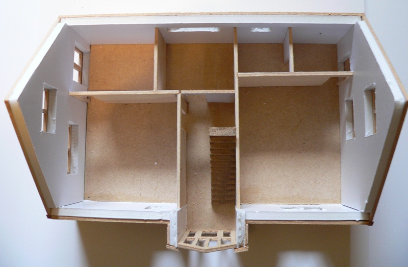
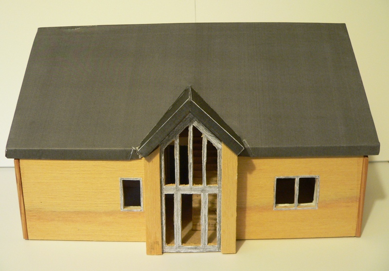
I found that model making was extremely useful, and after a bit of practice, very quick an easy from 2D drawings. The technique I used for the big model of the whole site, was to use the data from our topographic survey (usefully provided as a .dxf file) and use that to make a plaster base, with cut to length cocktail sticks as the spot heights, layers of 5mm thick foamboard as the contour lines and then plaster filler to create the landscape. The local model shop supplied textured grass, gravel etc, intended for use with model railways, and painting a coat of PVA glue over the surfaces, then sprinkling the texture powder over it was easy. The house and other buildings were made using either modelling liteply (easily cut to scale by spray mounting 2D drawings and then cutting it out with a craft knife), or for the larger models I used a mix of 5mm foamboard, with a skin of 2mm liteply, that was very close in scale thickness to our 480mm thick walls. I can talk you through making these models if you like, but they weren't hard to make. After around the fourth of fifth iteration of the detailed house model, to show my wife what the interior would look like, at 1/50th scale, so I could use 1/50 scale plastic railway model figures to show how people would look in the house, I'd got the process of printing off the pieces and making a new version of the model in around 30 minutes. -
Conceptual and detail design software
Jeremy Harris replied to LouiseSJPP's topic in New House & Self Build Design
I found that 99.99% of the professionals only wanted 2D drawings, and also that there was a general distrust of nicely rendered 3D drawings. To overcome the problem of some people not being able to visualise thing from 2D, I made scale models, one large one covering the entire site, that showed our proposed house in the landscape setting: And also a sequence of different, larger scale, models that I made for my wife, who struggled to visualise spaces from a set of 2 D drawings: I found that the first model, the one showing the house in the landscape, was exceptionally useful, as the neighbours, Parish Council and all the other people who were involved in commenting on whether our planning application should be approved, found it much easier to understand what we were planning to do from this model. If you have to deal with any local bureaucracy then I'm convinced that a scale model is more likely to be believed than any 3D rendered graphic.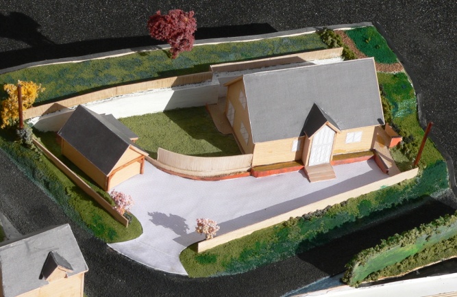
-
Conceptual and detail design software
Jeremy Harris replied to LouiseSJPP's topic in New House & Self Build Design
It depends how "hands on" you want to get, and also how much detail you need to provide for your local planning and building control people (not sure how it works in France!). I found that for planning very little detail was needed, just plan and elevation drawings plus a site and location map. The planners weren't interested at all in the internal layout, they just wanted to see how big it was, and how it fitted into the surrounding landscape. Any very simple 2D drawing package would have done the job, but as I already had AutoCad I used that. Our planning permission submission and drawings can be seen in this blog entry, that may help: http://www.mayfly.eu/2013/09/part-fifteen-the-site-is-finally-ready/ This blog entry covers everything I submitted to get building control approval, I'm not sure if there is a similar process where you are or not: http://www.mayfly.eu/2013/09/part-fifteen-the-site-is-finally-ready/ We opted to take as much risk out of the build as possible, so chose a frame supplier that also offered an integrated insulated foundation system. The cost of this was modest compared with the alternatives and it meant that all the detailed structural design was done by the frame supplier, as a part of the package. All told I think this was the best route for us, as it still allowed us to do all the basic design of the spaces we wanted etc, what they did was engineer this into a package that could be erected very quickly and have the performance we wanted. If going down this sort of route then all you really need in terms of software is a fairly simple 2D drawing package (something like Draftsight, which is free, would do very well) plus a spreadsheet to keep track of costs, do some basic calculations of performance, etc. I produced a very simple heat loss model that runs on Excel or Libre Office Calc and will allow the areas of the house, doors, windows etc to be entered, together with their U values, the anticipated ventilation rate and MVHR efficiency and give a prediction of heat loss. It's simple, and nowhere near as comprehensive as PHPP, for example, but it's useful for doing "what if" iterations, to what the effect of changing any component has on the overall heat loss. You can download it from the front page of our blog, the direct download link is here: http://www.mayfly.eu/wp-content/uploads/2017/01/Fabric-and-ventilation-heat-loss-calculator-Master.xls -
Welcome to the forum. Just like Peter, they were also the criteria we used when designing our house - a house with no bills for our retirement!
-
The MIs for our kitchen tap (which has three flexi tails, one extra for boiling water) say to put a little silicone grease on the O seals (the tap was supplied with a small sachet of the clear stuff) then fit the tails hand tight only up inside the base. The tails were long enough that I could feed all three down through the worktop hole from the top, one by one, so the ends didn't cause the things to jam in the hole (at a guess the flexi tails were around 18" long). Fitting the big plate underneath, plus the washer and long tubular nut to secure the tap was pretty easy after that. We've had no problems with leaks, even though the tails are only hand tight. In fact you can unscrew the tails two or three turns and they stay sealed, as the O rings seal into machined bores in the base of the tap, away from the threaded part, so they aren't working under compression at all.
-
It might work, but you would need to look at the thermal resistance up through the core of the ICF and compare it with other options, like putting the frame on tom of foamglass, or similar. TBH, any strip type foundation is going to be a fair bit poorer than an insulated slab, the question is really how poor it is and how well it mitigates the sole plate condensation risk under dynamic (not static) temperature and humidity changes. The main problem is that the standard interstitial condensation models tend to fall over when looking at this detail, IMHO, as they don't take account of the rapid changes in humidity that can occur near ground level in cold weather, the classic case being a very cold night that cools the sole plate down, followed by a bright sunny morning that warms the area around the outside of the base of the wall fairly quickly, creating ideal conditions for driving water vapour inwards, perhaps towards a sole plate that is below the dew point for the local water vapour concentration that penetrates.
-
I've not taken it apart, as it's in my torch and I doubt I'd get it back together again! As above, I think it must be a buck/boost configuration, as it lights the LED up below the normal Vf of a white LED, especially taking into account the inevitable internal voltage loss when operating at low voltage. It may be that they just use a low Vf white LED, and rely on the DC resistance of the inductor in the buck converter to limit the current, when the voltage is too low for the buck converter to oscillate. That might work, and might also explain why there is a current and brightness peak at about 4 V - that could be the point just below the start up voltage of the buck converter. I suspect it is really pulsing the LED at some high frequency when operating above about 4 V, and won't be attempting to smooth the output. Standard constant current switched mode LED drivers work like this, and it's one reason why finding ones that don't cause a lot of EMI is challenging.
-
Try showing them this report, that makes it clear that a passive slab will work fine on any soil: Kore Insulated Foundations Report.pdf Worth pointing out that a suspended slab requires more insulation in practice, as it has to deal with the much lower winter temperatures in the ventilated void, so it makes the house less energy efficient in cold weather and increases the heating system losses if UFH is used on the ground floor.