
Leaderboard


Popular Content
Showing content with the highest reputation on 07/04/16 in all areas
-
Having spent a fair bit of time reading through old posts, I thought it would be really useful to actually capture some of the most useful content, written by people who have actually installed theses systems themselves. NB there are a number of different suppliers of the components required. These suppliers will often offer a no obligation, free design service. Some custom builders take advantage of this service, and loosely work from that base design rather than a blank sheet of paper. Horses for courses. Firstly, JSHarris from Sept 2015 "It is, without a doubt, far easier to DIY an MVHR fit using semi-rigid ducting and a radial system ... in terms of ease of design and fitting radial semi-rigid wins hands down. Where it loses out is price, as the cost of the ducting, fittings and plenums is more expensive than a non-radial rigid duct system ...The only other downside I can think of is that adjusting flow rates when commissioning the system is a bit of a pain, as you keep having to move between changing the restrictor rings in the plenum and re-measuring the critical terminal." " The spec was pretty easy, as all I needed to check was that I could get the flow rates needed for the critical rooms (those subject to building regs max extract rate requirements) without exceeding the max velocity limit in the ducting of 2.5 m/s. In practice you can go over 2.5 m/s when on boost I've found, as the duct noise doesn't start to get intrusive until around 3 m/s. These flow rates were just from the building regs requirements in Part V.As a double check I looked at the whole house trickle ventilation rate from building regs, but that turned out to be unimportant in terms of system design if you have terminals in every room, as the flow velocities in the ducts are very low for trickle ventilation.I designed the layout of the terminals so that the air had to travel the longest path from the terminal to the extract point in each fresh air feed room. In those rooms the extract point was the door (specifically the gap under the door) so the fresh air terminals were fitted diagonally opposite the door in most cases, and usually in a corner that might otherwise be a stagnant air pocket. I didn't bother with detailed duct loss calculations, as I started doing them for the high flow ducts (kitchen, bathrooms) and quickly realised that for a house of our size the ducting was more than capable of delivering the flow rate needed without incurring either high losses or excessive duct air velocity.I ended up just running the ducts by the easiest route and doubling up on the kitchen extract duct (two parallel ducts to the same terminal) to ensure I could reach the high extract rate on boost. In practice I'm pretty sure that a single duct run would have been OK.I fitted the manifolds as close to the MVHR as possible, to minimise the length of 150mm duct needed. I doubt this is really critical, as a 150mm duct will flow a lot of air, but it was pretty easy for me to put the manifolds close to the MVHR. They need to be somewhere where you can get easy access, as when setting the system up you'll be fitting throttle rings to the ducts in them. Some of my shorter ducts are throttled back to the smallest hole in the ring, which is something like 20 to 25mm diameter, so that may give a feel for how little air is moving through these ducts most of the time.I set the system up with a hot wire air flow meter set into a 100mm diameter bit of duct attached to a 150mm duct adapter to make a home made cone to fit over the terminals. I put some felt around the bit that would be pressed to the ceiling to get a better seal and to prevent scratching the paintwork. The flow meter I used was a Testo (the previous version of this model: http://www.testolimited.com/testo-405-thermal-anemometer ) purchased from ebay secondhand for around £30, but still in cal. This made it useful for leak testing around the house as well, as the sensing probe is small and very sensitive to low air flow rates. Here's a photo of my test setup: Ventilation test method.JPG 10.35K (not accessible) I adjusted the flow restrictors to get the right rates on boost to start with, to comply with building regs extract requirements from kitchen, bathrooms, utility and WC, then balanced it on trickle ventilation rate by adjusting the flow rates on the fresh air feed ducts. To fine trim it and get the feed and extract matched I adjusted the fan speeds slightly in the MVHR, so in trickle mode one fan is at 25% the other is at 28%, just to overcome a small imbalance overall.Setting the MVHR up was a bit tedious, with a lot of running back and forth and changing throttle rings, but at least a radial system isn't as interdependent as a continuous duct system, where adjusting one terminal upsets the flow rate of other terminals that have already been adjusted on that duct run. There is a tiny bit of interaction on the radial system, but very little I found, and it only affected the boost rate extracts.The whole house ventilation rate on trickle was measured both by summing the individual duct rates and also by measuring the flow in the fresh air feed and exhaust air ducts. These are 150mm diameter, so I drilled a small hol in the side of them, big enough to take the flow meter probe (about 12mm I think) and measured the velocity in those ducts directly. I then calculated flow rate from that and compared it to the sum of the individual measurements to make sure they were about the same.I found that the flow rates fluctuate a fair bit with very small outside air changes, so you have to average a few readings to get something meaningful. Even a light breeze will cause the ventilation rates to change by 50% or more up and down over a period of a few seconds, as the pressures in the ducting are pretty low and easily affected by small changes. Ideally you'd do the testing on a dead still day, but they are few and far between, even in our sheltered location." SecondlyDeclan52 from November 2015, working from a component Suppliers plan: "As far as installation goes, when you have signed the deal and paid for the goods you will get a plan showing you the duct layouts and where the vents need to go. Just make sure you get accurate measurements of the unit and make sure it will fit. There are access holes on the top and side on mine so you use what ever one suits your build. Double check it fits as his duct run layout will be from this spot. You will have 4 pipes to and from the unit. Feed and exhaust from outside so you will need vent tiles or wall vents whatever way you are connecting to the outside. The other two are the fresh air back into the house and the extract from the house. You will have a larger diameter pipe maybe 150mm from the unit to a manifold maybe a meter long depending on your layout. From the manifold then it will have a duct going to each extract. They basically twist and clip in very easy to do. I had the full 50m reel downstairs between 2 trestles and a pole through it and just pulled the duct along to where it needed to go. Leave a bit extra just in case and you can trim it to size when it's all in and secured. Measure all where your duct ends are and record this so when you are cutting the holes in the ceiling you know the exact spot where they are. You can use a hole cutter or a pull saw whatever suits you. Keep the system off till all the work is done or it will get clogged up with sawdust and all the other airborne materials. Get his flowmeter and adjust the vents to suit. Some adjust at the manifold others on the ceiling. It's def not a hard job to do just arkward as you are wrestling with a 20m length of duct that never seems to want to go where you need it to go. Get all your ducting in first before the plumbers or sparks arrive as it will make your life easier. Both plumbers and sparks will want to be first to make there routes easier but look after number 1 and get in first. If the ducting and manifold are in a cold area like the eaves you will have to cover the ducts and manifolds with the like of rockwool or you will get condensation in them And finally, Bitpipe, from March 2016: "Just completed the plenum side of my installation using 65mm internal radial duct, through luck more than design I've pulled it off but there were more than a few head scratching moments. So, where to start I used BPC who did a design (which I loosely followed) and supplied all materials. Our frame was already locked at this stage so I had to work around what was there and some issues only became apparent when the frame was up. If you're still at design stage, give first thought as to where the MVHR unit goes, you want to minimise the runs (typically 160-180mm steel radial duct) from this to the external vents (which should be on the same wall to minimise unbalancing due to wind. 1.5m horizontal separation is the recommended minimum. Then think very carefully on where the distribution boxes go (one for extract and one for supply, usually sit them next to each other) - note that these vary greatly depending on the manufacturer, some are boxy, some are long and flat. Some have ports on all sides, some just on one. You want to get them reasonably central so that you minimise very long runs but this may not be possible. Some are designed to sit in between pozi joists but this does not always mean you will have room to get the 65 or 75mm duct connections to them as it can get very busy. You may need to create a cupboard (or sacrifice one) to house these and the duct. You'll also need to get the 160-180mm steel duct to these also. Think on how you'll get vertically to different floors, wardrobe or cupboard space is usually the answer. Then try and eliminate any physical barriers to running the flexi duct from the plenums to the distribution boxes, such as steels (spec penetrations now ) or gluelam beams. They will pass happily through pozi joists and you can get a reasonably tight bend on them if required but it then makes them very tricky to pull through, watch out for pinch points where you may have many ducts going through. Supply plenums usually sit in the corner of the rooms diagonally opposite the door and extracts above showers, or WCs or about 1m from extractor hoods in kitchens. We have double runs to extracts and single to supply. Good idea to consult with your sparky and plumber to make sure you're not going to make their life too difficult (i.e. foul a line of downlighters with a plenum). It's difficult to leave slack in the ducts for later alterations - always possible to shorten a run but not extend it. When installing, locate the plenums first and then pull the duct through from the distribution box location to there. My system just required the end of the duct to be neatly cut and an O ring slipped over the first rib and then pushed home & clipped in. WD silicone spray is essential to lubricate everything. Leave a decent tail at the distribution box end and mark the ducts with a sharpie so you know what's intake vs extract. I used 50m rolls of duct and put a piece of supported 2x4 through the centre before uncoiling as it can get tangled very easily. If you can draft a few mates to help then this really speeds things up as each tight bend needs manipulated to get the duct through. Watch out for nails through the joists from above and below too. It can get very congested when all the flexi duct comes together and I spent quite a bit of time rejigging ducts so they would connect to the distribution box neatly. I've not cable tied anything just yet, will probably use builder strap to keep them up out of the way and cable tie each connection to the distribution boxes as these don't have clips. The plenums are rock solid. Just starting on the 180mm duct now, I've already put 600mm sections in the wall for the intake/extract so they could be insulated & rendered around. BPC have given me loads of 180mm duct (i'll likely use 1/3 of what they supplied) plus 45 and 90 bends and some springy flexible duct also to make the final connections to the MVHR. And the golden rule is to get in first before the other trades nick the space" Thanks to all.1 point
-
The wood burner should, if the regs were worded sensibly, be negative points, because of the high toxic emissions and the fact that they are far from CO2 neutral in reality, but you're right, you will need to do a quick check of the DER and TER to ensure you're still OK (i.e. DER lower than TER). This is a two minute check on SAP, just change the heat source and see what the DER does. A bioethanol stove should score slightly better than a wood burner, I think (I don't have a copy of FSAP with me here to check right now). I'm with you on the mess! I fitted a wood stove to our second house when I was doing it up, around 25 years or so ago. The amount of dust and debris from carrying wood through the house was a blasted nuisance, but it was an old stone cottage with no insulation and full of draughts, so we needed the heat and put up with the mess. The next house we bought I made sure had central heating, with just a bottled gas coal-effect fire as a feature (which never really got used). We've never had an open fire or stove in a house since, always because of the mess, but with the recent highlight on the adverse health affects from burning wood I've come around to the view that the things are really pretty harmful, as well as messy.1 point
-
In my spare time of course1 point
-
Yes, there's a requirement that you provide a site toilet and hand washing facilities. Whether workers use it or not is up to them, a bit like wearing PPE. You also have to put up site signage indicating the PPE that might be needed and also warning the general public that building sites are dangerous and they should keep out. An adequate level of fencing is needed in order to ensure that access to the public is restricted - in effect you must provide a barrier that removes the common law right of access. Generally, this means having fencing and gates that are around the same effectiveness as the standard Heras stuff, but you don't have to use that particular fencing. The main issue is that you have to be able to close off the entrance with a secure gate that is enough to make it clear that any access has been restricted. You're not required to provide a site hut, and in the case of a quick build like an MBC prefabricated frame the house will be up and watertight in days, and then the inside of the house can be the site hut. I made the mistake of hiring a portaloo for far too long, at £25 a week, inc VAT. I should have bought a cheap cassette loo from ebay and plonked that somewhere in the house as soon as it was up, together with a water container and bowl for hand washing. I think I had the portaloo on site for around 3 or 4 months longer than needed. Providing a fresh water supply for making tea is a good idea, I had no drinking water on site so ferried over 25 litre containers from home. Having an extension lead set up in a handy corner to run a kettle is also a good plan. I provided a kettle, but IIRC the MBC lads had their own they brought with them. None of the other people working on site brought along their own kettle, though, so the cheap one I provided did get well-used. I also provided a first aid kit and an eyewash station, simply because I had both to hand (I have around 4 spare first aid kits that I've maintained ever since I used to be in the cave rescue team - never knew when you might have to grab one in a hurry and go on a shout and it was handy having them already in either car and at home). I'm not sure if you are required to provide a first aid kit or not, but it seemed to make sense to me to have one on site. The final thing I did was print and laminate some emergency contact phone numbers and addresses for things like the local GP surgery, the local A&E department, contact numbers for me and a nominated key holder and a few other ones that might be handy, like local pubs and the village shop.1 point
-
It can be another Celotex board product, It would sit vertically off the Celotex on the floor and against the wall. In your case it would be 100mm high so it comes up to the top of the concrete pour and stops the concrete contacting the wall. The thickness is limited by your wall build up, and what is "overhanging" the poured floor, ie. plasterboard plus skirting board, so the upstand is then not visible.1 point
-
Agreed, they are offering floating and "grinding" then sealing, so the costs look more reasonable. Will they do this on a structural slab? - a good find if they will. If you are having EPS under your floor, it may pay to hoover the EPS before the concrete pour. The power-floating can/will bring the little white balls of EPS up to the surface, which may not be noticeable when floated, but can become visible once ground.1 point
-
I didn't even think about the planes and helicopters. Back to the drawing board........1 point
-
Your not going to build a massive reinforced roof incase a plane falls out of the sky. If you live on a main road fair enough build a nice thick garden wall to stop the 1/1,000,000 chance of a car ending up in your living room. This leaves you free to build a house as you see fit in whatever build method that YOU want not what your architect wants.1 point
-
Let it dry out and once dry a bit of bleach and wash it down and don't plaster it till its gone incase it blows.1 point
-
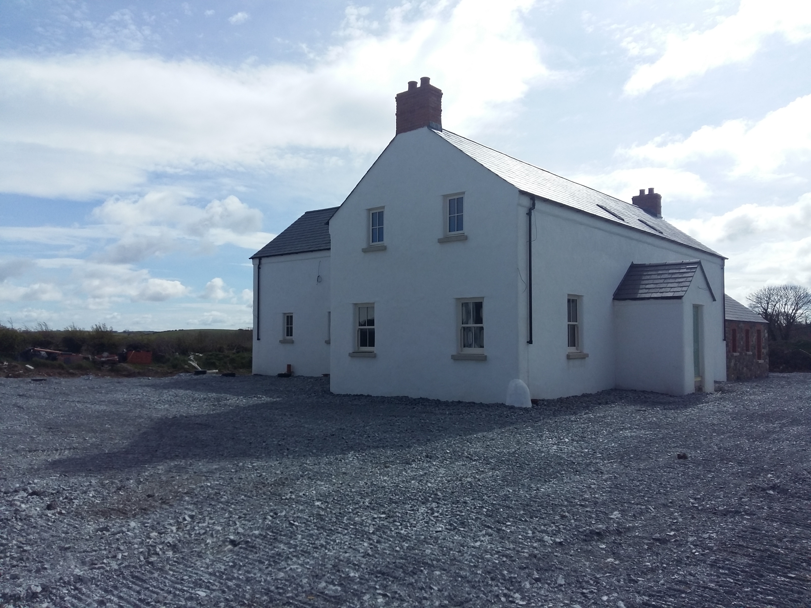
Thank you :-) The gullies weren't set when the guys were there to fit the downpipes and they wanted to make sure the lengths were right. I'm going to add another bracket about half way up each downpipe just to secure them against strong winds. There's been a little bit of progress in the kitchen again since it became weather tight and the beams have been added to the ceiling. I've also added a photo showing the front from the other end.

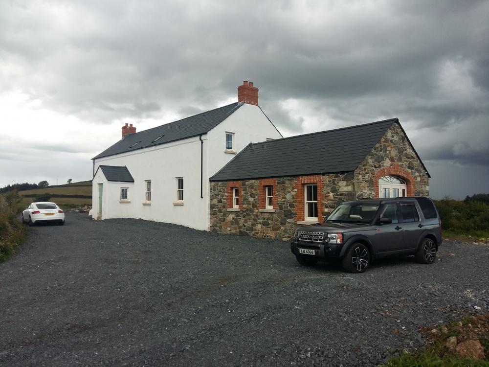 1 point
 -
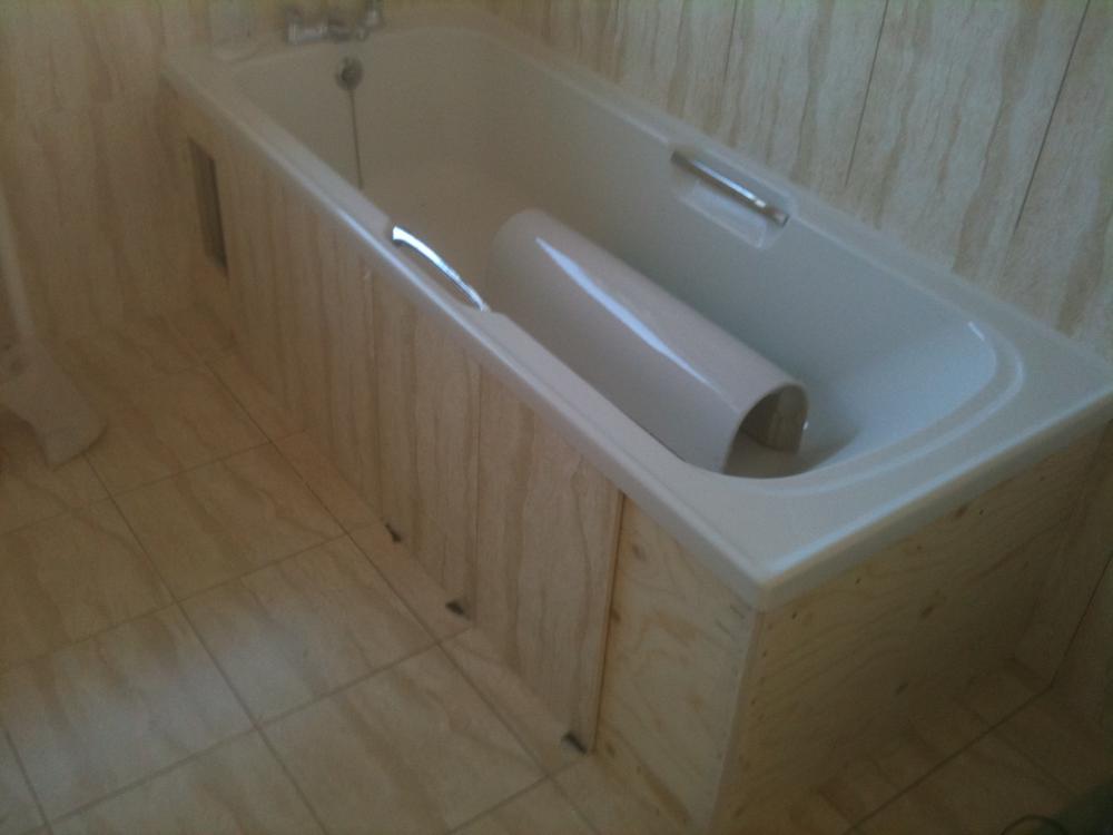
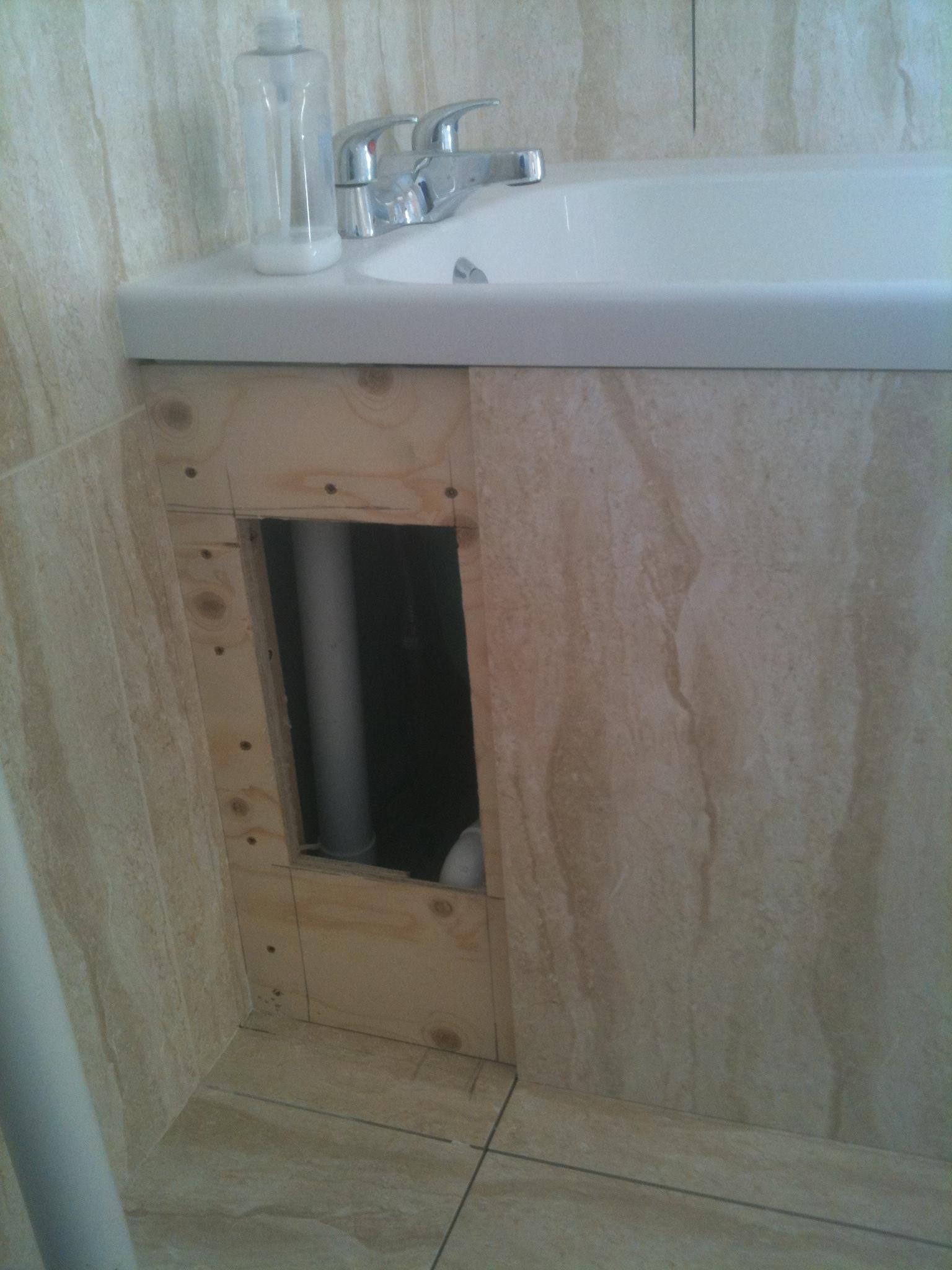
I usually cut a section of plywood out and fix a tile on with 4 or 5 50p size blobs of mastic. The tile the gets grouted as normal and looks flawless. I tell the customer to keep at least one full box of tiles, and the idea is if you need to get in ever, you just cover the tile in gaffa tape and whack it in the middle to break it. Remove it and clean up, change whatever and stick a fresh tile back. Fwiw most modern taps are all services from above . I only put an access option on these kind of jobs as there was also an air admittance valve ( on top of the white pipe shown ) so was more worried about that failing tbh.
 1 point
 -
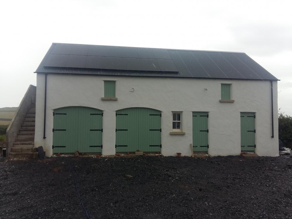
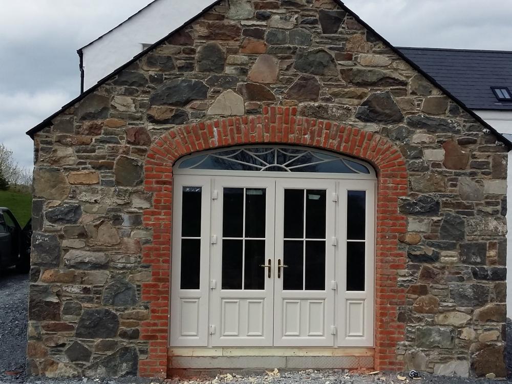
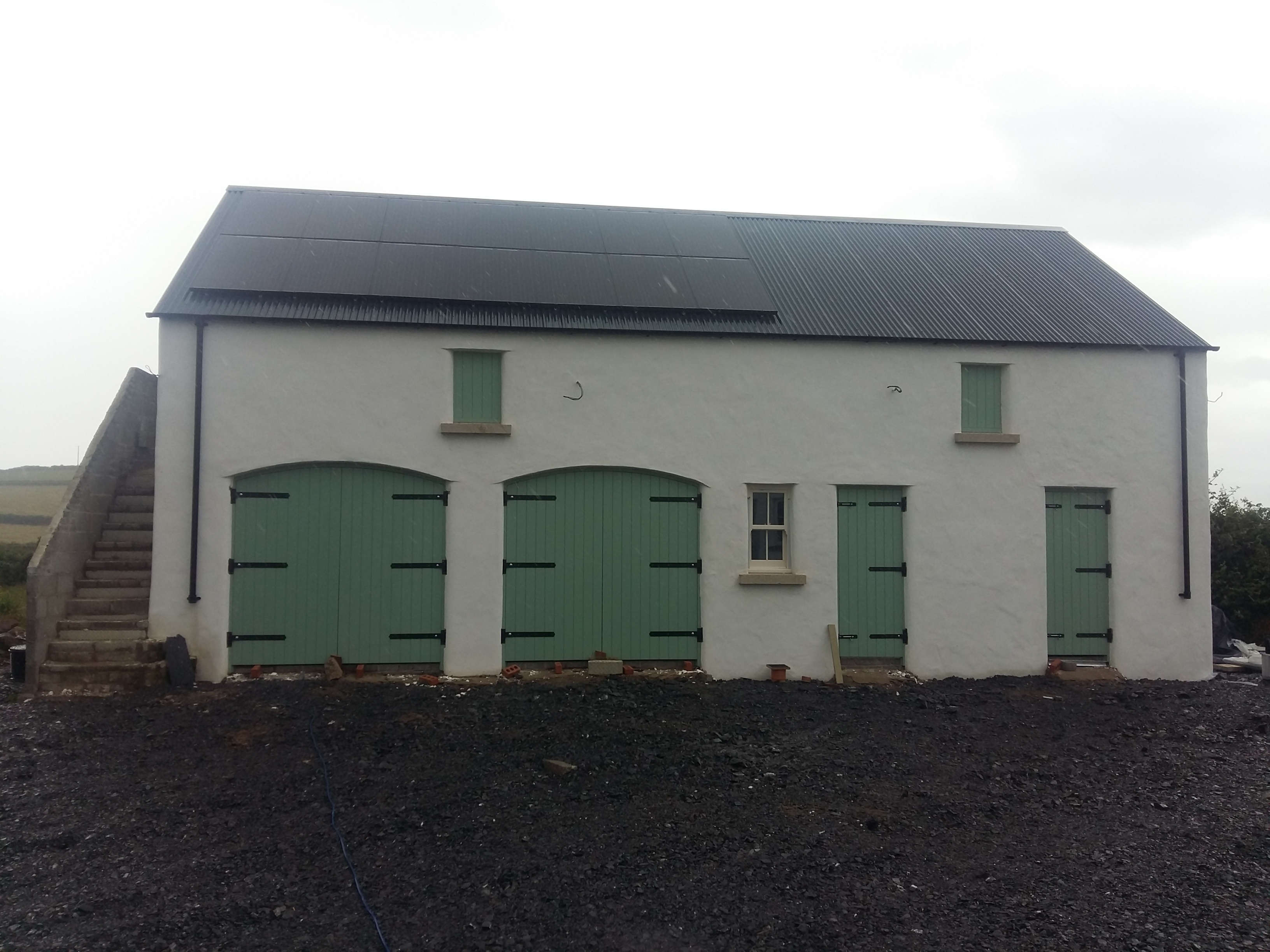
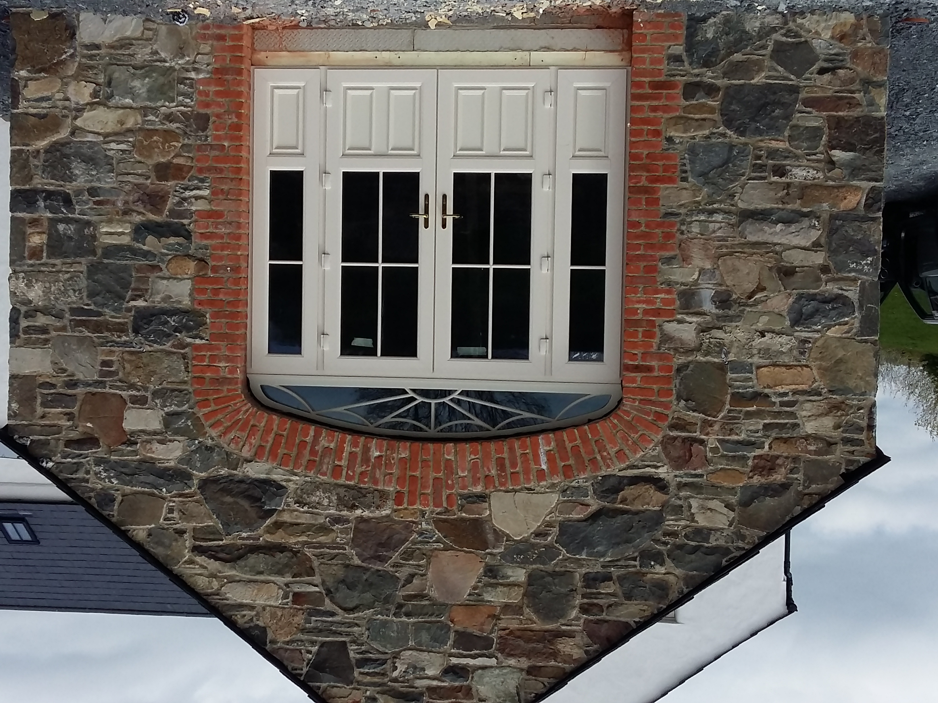
Thanks everyone, I'll check out the blogging section properly over the weekend Peter. Render is doing OK, I'll try to add a couple of photos I have on my phone? The garage doors were just fitted today and I've added a photo of the replacement French doors too.

 1 point


This leaderboard is set to London/GMT+01:00