Jump to content
  • entries
    7
  • comments
    91
  • views
    4328

The energy meter experiment


SteamyTea

2556 views

I am not sure how well it works yet, but it works in trivial cases i.e. a 40 W lightbulb and my fridge (once I had stopped stray morning light).  I am going to ask my neighbours if I can pop the Photo Diode on their meter as I don't want to stop the one that is already logging mine.

What would be good is if others, who have a lot more knowledge and skills than me (I am really just a chancer than fiddles about till it seems to work) could improve and add to it.

Things that would be nice are a remote sensor to save having to run a small bit of wire into the meter box.  A nicely made sensor cover that holds the magnet in place, and does not let stray light in.  A display, and an enclosure for the complete kit (thinking of you @Onoff and your plastic printing skills).

Remote, but not cloud based access may be interesting, but as will all new toys, after a few days, does not get used often.

Other 'things' could easily be added i.e. temperature, humidity, air pressure, but they are really stand alone items, though inside and outside temperature is useful.


So here it is, my feeble attempt.

What I have used to make my energy meter.


A shop bought energy meter

image.png.44b162879c936548933df82915e1f754.png

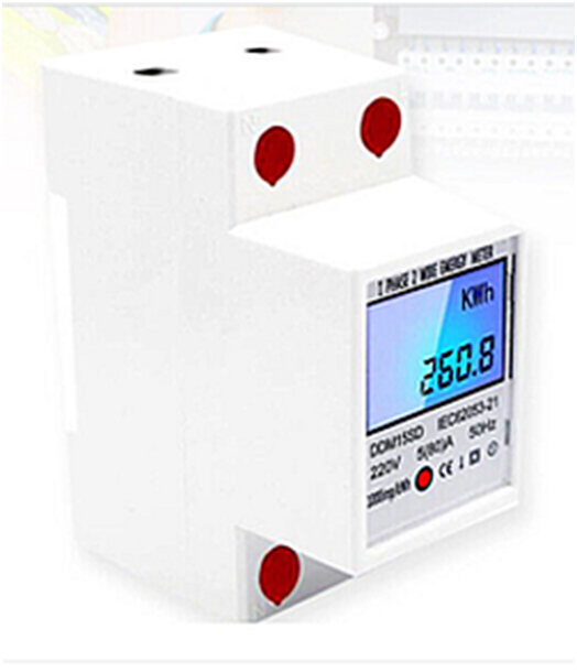
https://www.ebay.co.uk/itm/354118466147

I used this purely to test the power, 1 pulse per Wh, same as my main meter.  I will, as I bought 3 of them, use them on my 3 ‘night circuits’ once I have finished playing.


Some magnets with holes in the middle

 image.png.d1ee01e9900a09cf73327fcc569f0070.png

https://www.ebay.co.uk/itm/184928442876

These are to hold the light dependant LED onto the meter.  A suitably sized metal washer was super glued in place.


Some photodiodes to sense the red flashing light on the meter.

image.png.78c2cdfc5d5a4250c4bbbdf7a4824e5c.png


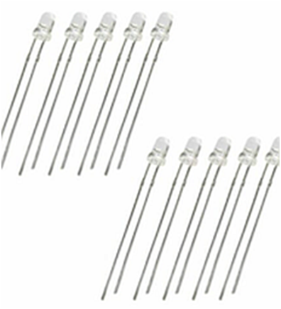
https://www.ebay.co.uk/itm/232690475106

This is the real magic, just wired in between a GPIO pin, 22 in my case and ground.  The important thing is to wire it in the ‘wrong way around’.  So the anode, the longer leg on the diode, is wired to ground, and the cathode, the short leg, is wired to pin 22.


A Raspberry Pi ZeroW 

 image.png.f63769877b0d0bad228a50bb670403c1.png

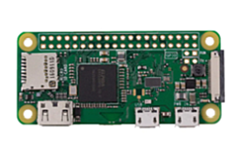
https://thepihut.com/products/raspberry-pi-zero-w

Just a bog standard RPi ZeroW


A header

image.png.b30e76d2f034532ecadcc38c642e6ad1.png

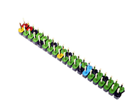
 https://thepihut.com/products/colour-coded-gpio-headers

Are useful, and I think you can buy the RPi ZeroW with them already soldered in place.  You need it to easily fit the RTC on.


A Real Time Clock

image.png.cc19547f571911d1dbf924eb09c8bf78.png

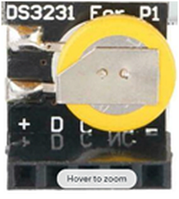
https://www.ebay.co.uk/itm/234603677979

While not necessary, I always fit an RTC (real time clock) as I cannot guarantee an internet connection all the time.  You have to muck about with the /boot/config.txt file to include the line


dtoverlay=i2c-rtc,ds3231


and edit the /lib/udev/hwclock-set file to disable the settings with the # symbol


# if [ -e /run/system/system ] ; then

#    exit 0

#fi


A USB to TTL Serial adaptor

 image.png.f6390e4394ab8ee9961485c90575650e.png

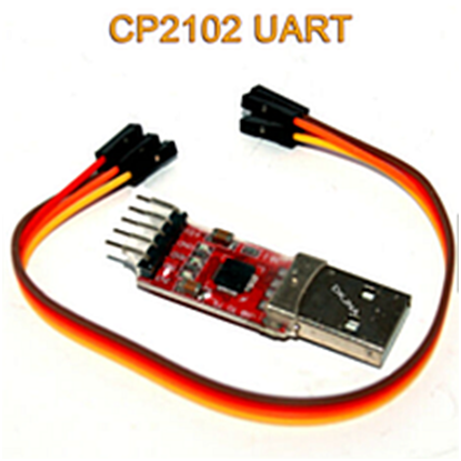
 https://www.ebay.co.uk/itm/203604196200

Useful when setting up a ‘headless’ RPi.  Just make sure to change the /boot/config.txt to inclide the line

enable_uart=1


The Code

The code I have used uses Python3 and standard libraries.

After much searching and thinking, I found that GPIOZero library was quite useful (https://gpiozero.readthedocs.io/en/stable/api_input.html) as it has some useful code for a ‘button’, or switch to the rest of us.

I also, included a block of code to create a daily *.csv file that automatically changes the filename every midnight.

All the code does is sense when the light dependant LED senses light, and when that light stops, it timestamps the daily *.csv file, then wait until more light appears again.

Simple, 3 lines of main code.


#!/usr/bin/python3

from gpiozero import Button

import time, datetime


button = Button(22)

def sort_time():

            dt = datetime.datetime.utcnow()

            runday = dt.day

            dt.day == runday

            ts = time.time()

            UTC = datetime.datetime.utcfromtimestamp(ts)

            logfile = '/home/pi/monitoring/data/meter-%s-%s-%s.csv' % (dt.day, dt.month, dt.year)

            tfile = open(logfile, "a")

            tfile.write("%s"%UTC + '\n')

            tfile.close


while True:

            button.when_pressed

            button.when_released = sort_time


What could be simpler.


The output is presented like this.


2022-07-09 13:05:38.577239

2022-07-09 13:05:40.028295

2022-07-09 13:05:40.374854

2022-07-09 13:05:50.753515

2022-07-09 13:05:52.390287


Each timestamp is equal to 1 Wh.


I do all the analysis in a spreadsheet.


39 Comments


Recommended Comments


Great write-up. So there's no 'rate limit' on the number of records - the more power you draw the more records are created. Might that not get a bit heavy if you logged a big load? like 100 writes to boil a kettle?

Link to comment
1 hour ago, Radian said:

100 writes to boil a kettle

I tried it in my kettle and it was fine. My CurrentCosts write up to 10 times a minute, large files are not really an issue these days.

There could be a secondary file that counts up from the first file every hour, then shows that.

It is those kind of details that others are better at.

It would be good if someone replicated my design and tested it, very easy to convince oneself that it is perfect otherwise.

Link to comment
1 hour ago, joe90 said:

wish I understood one word of that

Tis easy, even you can wire it up.

  • Haha 1
Link to comment

Wtf? 


You sketch it we'll CAD it / print it. I'm a 🐒 see 🐒 do kinda guy. 

Link to comment
54 minutes ago, SteamyTea said:

large files are not really an issue these days

No but the Rpi is writing to SD card if you're not using a RAM disk/network storage device/USB stick or HD. Most SD cards aren't really up to the repetitive write task but then again, they're dirt cheap.

Link to comment
1 hour ago, SteamyTea said:

Tis easy, even you can wire it up.

I could wire it up (with instructions) but does not mean I understand it 👀

Edited by joe90
Link to comment
16 minutes ago, Radian said:

Most SD cards aren't really up to the repetitive write task but then again, they're dirt cheap.

Got some that have lasted 10 years of logging.

And can easily change the file location to copy to a memory stick at the same time.

Link to comment
11 hours ago, Onoff said:


You sketch it we'll CAD it / print it

Thanks. Shall see what I can knock up.

Link to comment
11 hours ago, SteamyTea said:

Got some that have lasted 10 years of logging

Probably a genuine card then. The current market is peppered with fake SD but USB sticks generally fare better.


Thinking about how someone with no soldering skills could assemble this, some female to female 0.1" patch leads could be used to connect the photodetector to the 0.1" header on the Rpi so long as it was purchased with the ready assembled header pins. And to avoid the need for the USB to TTL serial adapter, with WiFi on the Pi, you can SSH into the command line by adding a couple of files to the SD card after writing the Operating System to it: Step by step Instructions here

Link to comment
10 minutes ago, Radian said:

Step by step Instructions here

I may give that a go as I have never managed to get it to SSH in with the 'create an empty file' method.


10 minutes ago, Radian said:

no soldering skills

Can you get small crimps to join very small wires.  Though that is more things to buy.


I am going to look around the shops and see if I can find anything that can be easily modified to make the LED holder.

I used a bit of rubber pipe and some epoxy. after super gluing the LED into place.

Picture to follow in a few minutes.


IMG_20220710_103411917.jpg

IMG_20220710_103329341.jpg

Edited by SteamyTea
Link to comment
44 minutes ago, SteamyTea said:

Can you get small crimps to join very small wires.  Though that is more things to buy.

The crimps and plastic shells themselves are inexpensive but the crimping tool you need is expensive. Not worth it if you're only doing this kind of thing on rare occasions. The patch leads are one way around it and You can also get male to female versions to make daisy chains in order to get a bit more length.


Link to comment
2 minutes ago, Radian said:

The patch leads are one way around it and You can also get male to female versions to make daisy chains in order to get a bit more length.

I suspect, anyone that fancies making one, will be a bit of a DIYer.


So you had any thoughts about adding a cheap display, but not one of those tacky LED matrix ones. Something like this.

https://www.ebay.co.uk/itm/165511794894


And the code to display useful stuff, i.e power, energy, time, price, temperatures.

It is that side of it that I have never done before and find frustrating.

Link to comment
10 minutes ago, SteamyTea said:

And the code to display useful stuff, i.e power, energy, time, price, temperatures.

It is that side of it that I have never done before and find frustrating.

OK, so there's a thousand different ways of going about this. But I recommend just one: Node Red.


Node Red can easily be installed in seconds and has a fully graphical interface that presents itself in any web browser. You can create dashboards and have it all show up on the sort of display you've found there, as a full screen. But as it runs on a webserver on the Pi you can also access it from any other PC, tablet or smartphone on your LAN. You can do anything with GPIOs and timestamps etc. like you've done in Python.


The other thing I'd highly recommend is to install a MQTT broker This gives you simple messaging between things and is fully integrated with Node Red, Python etc. Say, for example, you had other energy meters connected to Pi zeros. You could publish MQTT messages containing the power info and collect and display them all in Node Red. You could even communicate between the Python script your written and Node Red for display.


Thus you have one central server Pi running Node red and the MQTT broker (and have it also taking some measurements) and have as many satellite devices as you like. MQTT is a great way to communicate with ESP8266 modules as well, so you could slim down your measuring devices for temperature, power etc. with a £3 device!

Link to comment
19 minutes ago, Radian said:

ESP8266 modules as well, so you could slim down your measuring devices for temperature, power etc. with a £3 device!

 Could they be made to run reliably for a couple of years on a couple of D batteries like the CurrentCost does. My old clamp ones lasted 5 years transmitting away. The Optisence uses just one D cell and lasts at least 2 years, as long as I don't put my metal frame collapsible chair in the way. It is better that a tinfoil helmet at blocking a signal, and you can sit in it.

Edited by SteamyTea
Link to comment
1 hour ago, SteamyTea said:

 Could they be made to run reliably for a couple of years on a couple of D batteries like the CurrentCost does

Possibly. CurrentCost sends a radio packet every 10 seconds which is not possible over WiFi, on batteries. But WiFi can be brought up, say every 10 minutes, and the last 10 minutes of data could be transmitted including a temperature reading. The ESP can also sleep between pulses so minimising power consumption. Alternatively ESP32 has more in the way of power saving including Bluetooth LE. At the end of the day they're equally easy to work with. Anything you can think of doing has very likely been done and put on Github for inclusion in your code.

Link to comment

Great work!  Could do with 2 of them to the same cpu - we have a main meter and a PV meter.  I think we might need another meter again really, in series with the main one but backwards, to measure power flow both ways.  Then we have V2G....Why is it so complicated?!


Some elec meters have isolated outputs, as well as an led, that pulse.  This one that I've used does, pulsing at 1 pulse per Wh - prob worth getting that sort if you're buying one.

I used a 10k pullup resistor to 3.3V, connected -ve to cpu 0V, and fed the pulse signal into a cpu input:


https://www.amazon.co.uk/Electric-Electricity-Backlight-Certified-Calibrated/dp/B096YBRRYK/ref=sr_1_7?crid=3VCCVWXIONQEG&keywords=electricity+meter+din+pulse&qid=1657462762&sprefix=electricity+meter+din+puls%2Caps%2C106&sr=8-7


Link to comment
11 minutes ago, RobLe said:

Could do with 2 of them to the same cpu

Should not be a problem as the RPi has loads of GPIO pins, 

Just add


button1 = Button(23)


and


            button1.when_pressed

            button1.when_released = sort_time1


Also add


def sort_time1():

            dt = datetime.datetime.utcnow()

            runday = dt.day

            dt.day == runday

            ts = time.time()

            UTC = datetime.datetime.utcfromtimestamp(ts)

            logfile = '/home/pi/monitoring/data/PV-%s-%s-%s.csv' % (dt.day, dt.month, dt.year)

            tfile = open(logfile, "a")

            tfile.write("%s"%UTC + '\n')

            tfile.close


Though there is probably a more elegant way to do the above.

Edited by SteamyTea
Link to comment

This is a great little device, and I will build one but using a WEMOS D1 Mini device,  however I guess there must be a rate limit somewhere in this version and if you add in additional meters it will arrive much sooner, if its coming at all. Several concepts could, but don't think they will, indicate that although a terribly simple and reliable idea it may fail in exremis. I am not saying any of this is a problem for this system as implemented but it may be if you extend it without getting to grips with the nature of real time systems.


Firstly the RPi OS is not really a real time system so although the quickness of the hand deceives the eye it can only do so much in a given time and probably cannot do things at a given time! You can programme it to give priority to aspects of the code but when everything is competing this become a real art - games programmers will tell you this is their biggest headache - my fraction of the CPU is this and spread over....  Real Time OS's do guarantee timings, it is the definition of a real time system that time critical events are handled. This all means that although the RPi will probably do this reliably it may miss a pulse here and there while it is busy housekeeping - a headless system will take less time doing this naturally and this system is not being asked to operate at very high speeds (See below)


So, secondly, how fast does it need reliably to be. Most people have a 100A connection so if one was running that flat out (Approx 17Kw {240 x .707rms x 100A} of resistive stuff running) those pulses are going to be coming reasonably quickly, perhaps 5 pulses per second, and you might worry that your Rpi, usually running with Raspberry Pi OS, is busy doing some housekeeping while a pulse comes and goes without being spotted. This is assuming that the GPIO library does not implement any interrupt based process - if so all this is tosh - someone will tell me (See link below)! The sampling is not really a problem of the frequency of the pulses but rather their length, how long are the pulses anyway? If I can find a photodiode around here I will have a look at my meter and find out! Do they change length depending upon frequency one also wonders? For now I am going to work on 30ms pulses as a guestimate. So you need to guarantee your sample rate at least meets the Nyquist criteria (I was always taught that simplistically you need to sample at least twice the highest expected frequency / period to be reasonably sure you spot everything). So this means you need to sample at least every 15ms to be sure of catching a pulse of light. Rpi can sample at MHz so sounds like no problem but with an non RTS OS you might find that the writing of that CSV file actually takes a period of a of 15ms and you may have missed your pulse.


The good news is that even if the libraries don't implement the interrupt driven GPIO functions you can still do it and there is a very good explanation of all this here: https://roboticsbackend.com/raspberry-pi-gpio-interrupts-tutorial/ 


This world we are living is getting increasingly demanding of the union between mechanical, electronic and software systems. So if you can get the electronics to do some of the work the RPi does not have to be so real time. I think the Rpi has a PIO that can be set up as a pulse counter which you can just read anytime, count the difference - measure the time between and it recycles at the top but I may be wrong on that one. 


Link to comment

@MikeSharp01


As a test, I have set up an LED to flash for 0.01s then wait for 0.03s.

Left it logging, expecting a large file when I get back.


I think that will work out at 25 Wh per second.

90kW draw.

Few houses will go above 20 kW.

Dropping the odd Wh is not really a problem, and I think my CurrentCost does this anyway.


I did initially try to append to a list, then when the list got to length 10, timestamp it.

Was not very successful.


Be interesting if it works in the WEMOS D Mini.  I have some ESP 8266s, but not that good at micropython, not that good at python.

I did wonder about the file write time, if I deleted the tfile.close line, what are the consequences?

Link to comment

I actually don't think you have a problem. I need to find out if the python libraries implement the interrupt driven features but either way as you have the pi doing only a couple of things it will be fine. The problems come down the track if you get the pi doing more jobs and loose track of what is happening where and when in the system.

Link to comment
1 minute ago, MikeSharp01 said:

I actually don't think you have a problem

It was still logging when I got home a few minutes ago. File was almost 7 meg.

Just left it going and shall see what is happening in the morning.

I should be able to calculate how many pulses have been missed. Would be happy if it was less than 1%.

Link to comment

Ok so I have been working up a ESP8266 based equivalent of the Steamy counter. Although it broadly works I am having a real struggle getting the RTC to work reliably. Technically I don't need it as the receiver end could do all that, I could use the millis() functions to create quite good timing and I need that anyway to measure the interval and get a rough idea of instantaneous KWh. Could do this better with the 32KHz pulse train from the RTC if it was enabled on the boards I have - same as Steamy's. I have tried a slew of libraries but I still regularly get a bus conflict error on all three of my RTC chips and they all behave perfectly on an Arduino nano. As the RTC is currently managing the sensor timings - I put a DHT22 on the board as well for fun, I guess I need to fish out my logic analyser and look at the timing on the I2C to see whats going on although the scope would show me if the edges are fuzzy / noisy. I decided to echo the flashing LED on my sensor and made a bracket I can just tighten on the meter so nothing is actually fixed to it. So work still in progress I guess. 

16586658499743424359774414587329.jpg

Link to comment
20 minutes ago, MikeSharp01 said:

Ok so I have been working up a ESP8266 based equivalent of the Steamy counter

Going to be interesting to see your code. Never thought of adding an RTC to one.

Have fitted a DHT22 to them before. 

Link to comment

Create an account or sign in to comment

You need to be a member in order to leave a comment

Create an account

Sign up for a new account in our community. It's easy!

Register a new account

Sign in

Already have an account? Sign in here.

Sign In Now
×
×
  • Create New...