SimonD
-
Posts
1941 -
Joined
-
Last visited
-
Days Won
10
Everything posted by SimonD
-
Where does the discharge pipe go? There should be some easy means to see if the prv is letting by so either a tundish or a pipe termination outside where the pipe is turned back on itself towards the wall to stop hot, over-pressure release squirting into someone.
-
In case it helps you to feel better, we had a full topographical and lazer scan of the existing building to provide base dwg files as most of this was staying in place, then had a measurement survey by an architectural technician and again by an architect. I had to admit I thought we had it covered until a Polish brick layer kindly informed me that the back of the existing house was 120mm longer than the front. Cue a run to the phone to stop production of the curved glulam beams all ordered at the same length. In the end the glulam company did a fantastic job of manufacturing 3 different length curved beams for the main structure. The only pain for me was laying the metal standing seam roof onto a not square roof and hiding that it's not quite square! As lesson learned in not demolishing and starting again, but I do wish professionals could measure properly 🙄
-
Engineers not needed at all. 😉 A long long time ago in what feels like a galaxy far far away, I used to run document control for projects building anything from oil rigs and oil refineries to pharmaceutical plants all over the world. The engineers used to come crawling to us to ensure the right drawing versions were in the right place and the right time, especially when we got to construction drawings and sub-contract tender and issue. Nowadays, unless you've got good prior experience, some companies like the one I worked for ask for a Masters in Library Science for senior roles doing this.
-
No, fully installable from the outside as there's an expanding seal and a tightening too. Simple as - BTW - With a strap boss you need access to both sides of the soil pipe.
-
Just use the Macalpine mechanical bossconn as I linked to above - all you need is a hole saw and then use the compression fitting, so no messing around with cements or glue, or solvent weld reducers, or having to wrap around the soil pipe. Takes a couple of minutes max and you don't have any worries about whether the connection has been properly sealed as quite often happens with the wrap boss. The advantage of the Macalpine is that you can even use then for the blow offs from UVCs and boilers whereas the regs guidelines state you should NOT use wrapped bosses for these, but mechanical ones only. The 40mm version direct from Screwfix: https://www.screwfix.com/p/mcalpine-mechanical-pipe-boss-connector-black-40mm/55722 Simple and no mess
-
I tend to buy this one: https://mcalpineplumbing.com/traps/condensate-traps-and-fittings/mechanical-soil-and-rainwater-pipe-boss-connector
-
Communicating with the builder
SimonD replied to Bancroft's topic in General Self Build & DIY Discussion
That could be a bit of a challenge. Quite some time ago I was involved in a large litigation against a big company and some relatively new law (as in it had come into effect only about 12 years prior so case law still maturing). Part of that case involved debating whether the use of 'may' in the legislation actually meant 'must' or 'shall.' And if legislators and judges don't even know the meaning...... -
Recover, Battery Storage units £745 for 5kWh
SimonD replied to BotusBuild's topic in Electrics - Other
It's an interesting proposition, certainly. I've just looked at the company details and as it happens I've met one of the guys involved in this, but at this time it was in another company name - ecomove, which sold e-bikes, e-mopeds, e-scooters etc. in Bristol and has now changed its name and purpose I suppose. It's a small company carrying quite a lot of current liabilities. This is not necessarily a negative, it would just depend on cash flow of the business and the likelihood of being around if and when you want to scale up or you had an unfortunate warranty claim - and we know lots of much larger tech companies that do u-turns on products leaving customers in the lurch, so it's a risk for everyone. Good luck to them I say, I hope it does well. It's certainly something that's piqued my interest.- 1 reply
-
- 1
-

-
Cutting XPS insulation?
SimonD replied to Alan Ambrose's topic in General Self Build & DIY Discussion
What do you mean by reasonably accurate? I've used my jigsaw with a blade with 150mm cutting length on both woodfibre and eps at similar angles to this. With this you need to make a jig so you have a flat surface on with the rest to jigsaw as it won't make the angle if using the large flat area of ther xps. The other option is to make up a plywood jig that sandwiches the xps and gives you a cutting guide to rest something like the Bahco insulation saw on. I'd probably for for the second option. But if money is no object: https://www.festool.co.uk/products/cordless-products/cordless-insulating-material-saw/577231---isc-240-eb-basic-gb https://produkte.mafell.de/en/sawing/insulation-saw/insulation-saw-dss-300-cc -
Yes, absolutely. It doesn't just help with leaks, it helps lubricate the olive and nut so it's much easier to tighten it up without horrible squeeks and judder. On larger diameter compressions, you can use a bit of the paste on the thread which helps a lot too. The other thing you're going to be swearing about is the use of primary pro insulation. God awful stuff and the sealant is a messy nightmare - you also have to mend the outer protective layer on regular occasion. I only use Armaflex or Kaiflex with the adhesive and tape. TBH I now use trunking wherever possible now. Also, your anti-freeze valves shouldn't be installed on top of each other, but about 150mm apart. But what you can do with your situation is get the half bend covers like these: https://www.bes.co.uk/inta-zeroguard-anti-freeze-valve-protector-26812/ so if the top valve dumps its contents, it doesn't pour it all over the one below. An alternative in some instances is to have 1 anti-freeze valve at the lowest point of the pipework. And lastly, to be picky, you've got a lot of weight hanging of the connectors on the heat pump, no pipe clips until the pipe goes through the wall and this is what's holding the weight of the pipes. Personally, I would have run the flexis straight from the heatpump and then have the isolation valves on hard pipe properly clipped to the wall for support.
-
Replacement heating for an Old Farmhouse
SimonD replied to Iceverge's topic in Boilers & Hot Water Tanks
Way back when I was at uni studying aerospace engineering we spent time with one of the profs who assigned us a project developing exploratory approaches to more effectively harvest waste heat from power station cooling towers - either to inject this waste energy back into the heating process or take it elsewhere (yes, i know not really aerospace but the prof had a strong interest in energy conservation and it taught us quite a bit). This was a long time ago and heat pumps were very much part of the ideas. We're not very good at thinking this way, unfortunately, but better in other countries where they employ district heating. -
Today I had a call from a mate who was going to install an oil boiler and now wants to talk heat pumps!
-
Worcester Bosch Greenstar 8000 System Boiler Issues
SimonD replied to EinTopaz's topic in Boilers & Hot Water Tanks
I'm not that surprised. Sometimes it's better to have a system that is not too reactive and reactivity can significantly reduce efficiency. I think the figures in test A are okay. But I also caution against focusing too much on just the boiler temperatures and consider radiator temperatures and room temperature changes in relation to room volume. That way you'll properly know if the whole system you've got is in the right ball park. What are your expectations of what your heating system should be doing - specifically in regard to heating the space? I'm still of the belief that to get this thing running properly, you need to add some decent modulating controls, like weather compensation - but that, I know, is not what you want. -
ASHP outdoor unit heating pump Q
SimonD replied to BotusBuild's topic in Air Source Heat Pumps (ASHP)
Yes indeed, but for the really geeky ones of us, you've got to use Reynolds and relative roughness depending on material and even better the fluid temperature, and then using the Reynolds number you can even geek out over whether the flow is laminar, transient or turbulent 😊 This free calculator is pretty good: https://www.h2xengineering.com/pressure-drop-calculator/- 35 replies
-
- 1
-

-
- vaillant
- arotherm plus
- (and 1 more)
-
ASHP outdoor unit heating pump Q
SimonD replied to BotusBuild's topic in Air Source Heat Pumps (ASHP)
Yes they're crazily low. By my calculation the pressure drop in your longest ufh loop, 95m and flow rate of 2l/m is something like 12.8kPa. And then we have 10m on the 28mm pipework, assuming up to 7kW is just under 3.5kPa. So you are fine.- 35 replies
-
- 1
-
-
- vaillant
- arotherm plus
- (and 1 more)
-
It's funny the cash in hand malarkey. From the other side, it's so common for me to be asked by customers if I'll do the job cash in hand. I never do jobs cash in hand because they're the ones that show up the nature of the customer - they want cheap cash in hand deals but at the same time also want all the regulatory sign off and building regulations notifications is incredible. And they want all the back-up as and when suits them. As a trade, you need your wits about you to choose your customers wisely too!
-
ASHP outdoor unit heating pump Q
SimonD replied to BotusBuild's topic in Air Source Heat Pumps (ASHP)
I think there are 2 options here. 1. is to calculate the press loss in each loop to correctly determine the index circuit and then see if you have enough residual head at the heat pump. My suspicion is you probably do. If you wanted to do this then as you have the flow rates already, you might already have the pressure loss figures from the design documentation somewhere? If not, the pressure loss can be calculated from the flow rates. It's a bit laborious. 2. is you just take a punt and remove the buffer and additional pump and see what happens! I think you'll probably be okay, we won't know for sure until you get it up and running. Then there remains the question as to why they installed a buffer in the first place. Was it: - just a mindless design that plonked it in there; - to do with a calculated or feared pressure loss issue; - to do with system volume as your system doesn't hold the minimum volume per minimum kW output of the heat pump; - to actually buffer excess output from the heat pump as it's oversized? I would be worth doing a system volume calculation to make sure you have sufficient volume. That way if you don't, you could plumb in the buffer as a volumiser and this will save you a headache and repipe if you just cut it out and then have issues. The last thing worth doing is to understand your house heat loss co-efficient - this is how much heat your house loses per Kelvin change in outdoor temperature. To do this we need your calculated heat loss at the required design outdoor temperature and design indoor temperature difference. This figure is useful because we can then find out at what outdoor temperature the heat pump will reach minimum modulation to understand where it might start to cycle and then understand if the buffer was put in for this reason, although I doubt this because the buffer is so small. -
ASHP outdoor unit heating pump Q
SimonD replied to BotusBuild's topic in Air Source Heat Pumps (ASHP)
This is critical. Your index circuit basically means the sum of the sections of your heating system that adds up to the greatest pressure loss. For every meter that your heating water flows through a pipe is loses pressure. To know whether the pump can deal with this, we need to know the maximum pressure it has to overcome and at what flow rate. If you look at your specification chart, you have a max flow rate of 1205l/h and at this flow rate, if you look at your chart, it gives a residual head of just over 4m head. To know if the pump will be okay with this, you need to know if the circuit that has the greatest pressure loss is less than 4m head. Do you have a circuit diagram or do you know how your heating system is plumbed? -
So a little update. I've stripped back the plaster on the other side and it appears this has 200mm bearing also. Am I correct in assuming that a concrete lintel for a doorway under 1000mm will be okay with 100mm bearing each side?
-
One of the bits of my house remaining is a hallway where towards the end we have a doorway that was there with the original house. The hallway is wider than the doorway. The doorway is in a single skin brick wall right next to a brick pier. The wall is structural in the sense that on top of the wall I have a wall plate upon which there are doubled up bearers of 45 x 175 standing on edge along the top of the wall to which joist hangers are fixed for all the 1st floor flooring. It doesn't take any roof loads but there is a stud wall above. These double bearers span the whole width of the doorway extending to the end of the house in one direction and about 500-750mm the other side. Originally I thought this doorway would be fine but now we've got to plastering stage I've decided it all closes up the doorway too much and it just feels too narrow. The original lintel is a concrete one that I know extends about 200mm into the pier and about 150mm to the other side. It's the other side at 150mm where I need to open out the doorway. I was first wondering if I could use an SE's suggestion of doubled up studs anchored to the wall, but then I don't really gain much although maybe just 50-75mm would make all the difference, who knows. Are there, for example any metal brackets that can be fixed to the wall that would support the lintel? Or is it possible that with the doubled up bearers I might not actually need this lintel any more as this was the old exterior wall holding up a concrete tiled roof? This is probably not that straight forward, but does anyone have any suggestions as I really don't fancy the work required to take out this lintel and replace - and yes, I know I should have thought about it sooner 🙄 Thank you!
-
ASHP outdoor unit heating pump Q
SimonD replied to BotusBuild's topic in Air Source Heat Pumps (ASHP)
So what we need to know is which exact model do you have - what is its power output? Do you know the index circuit pressure loss for your heating system? And what is the property heat load? -
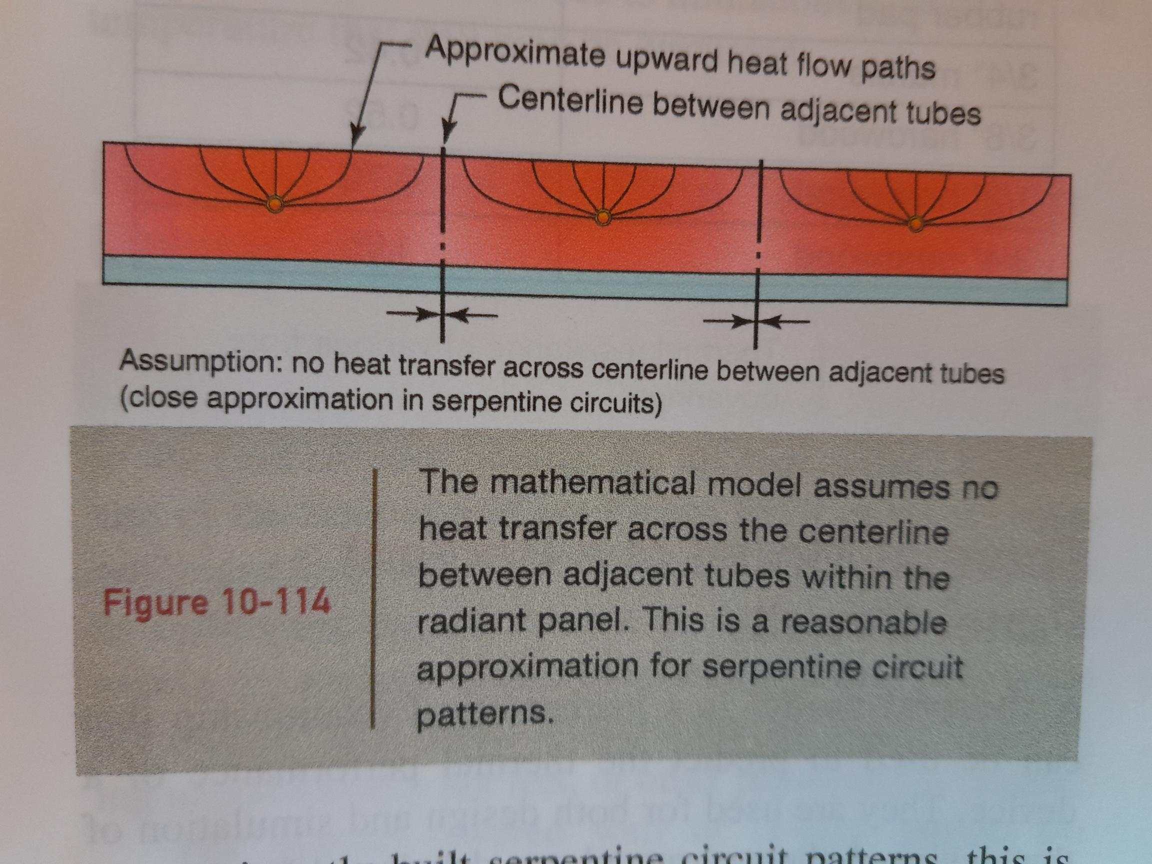
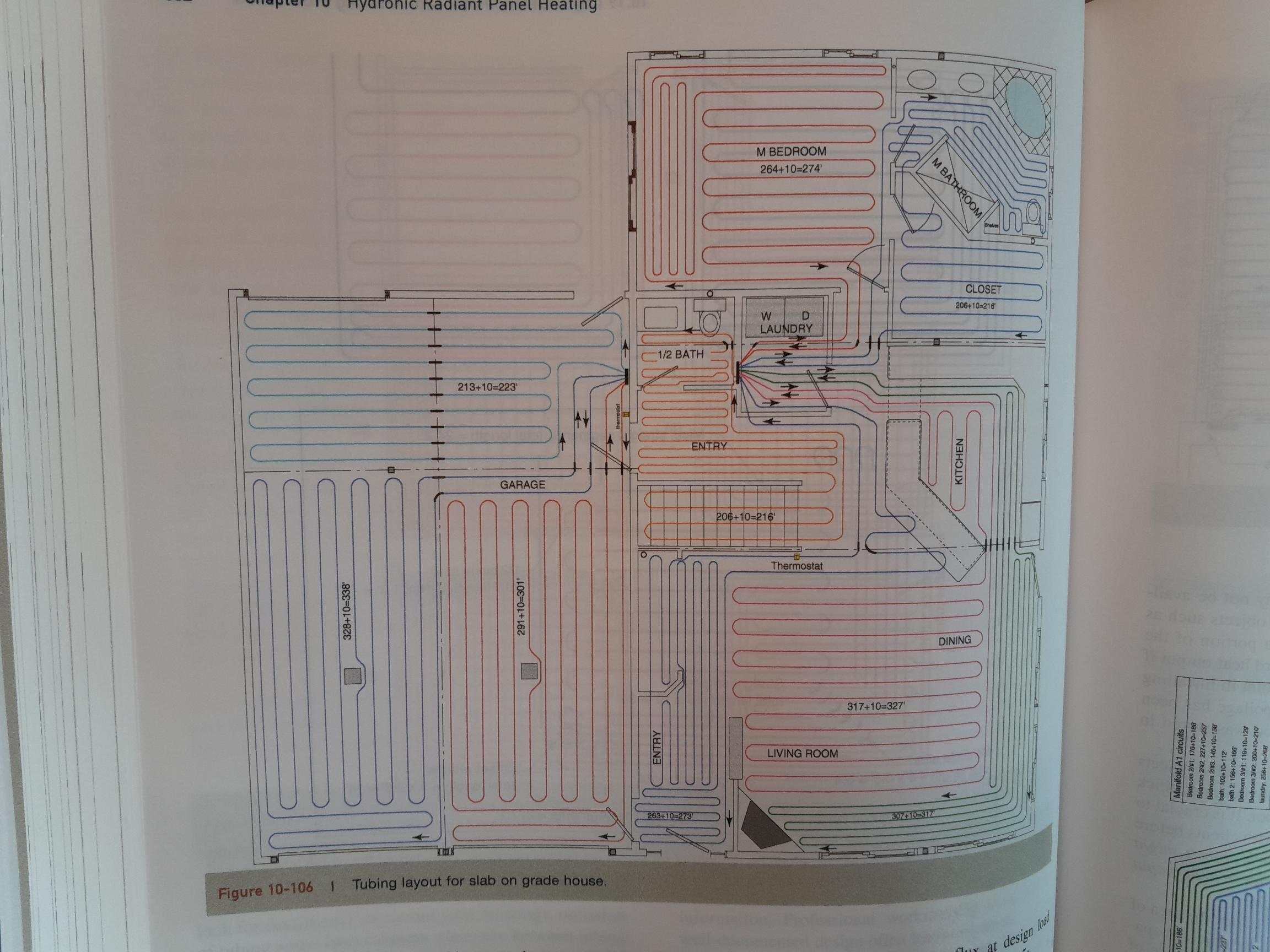
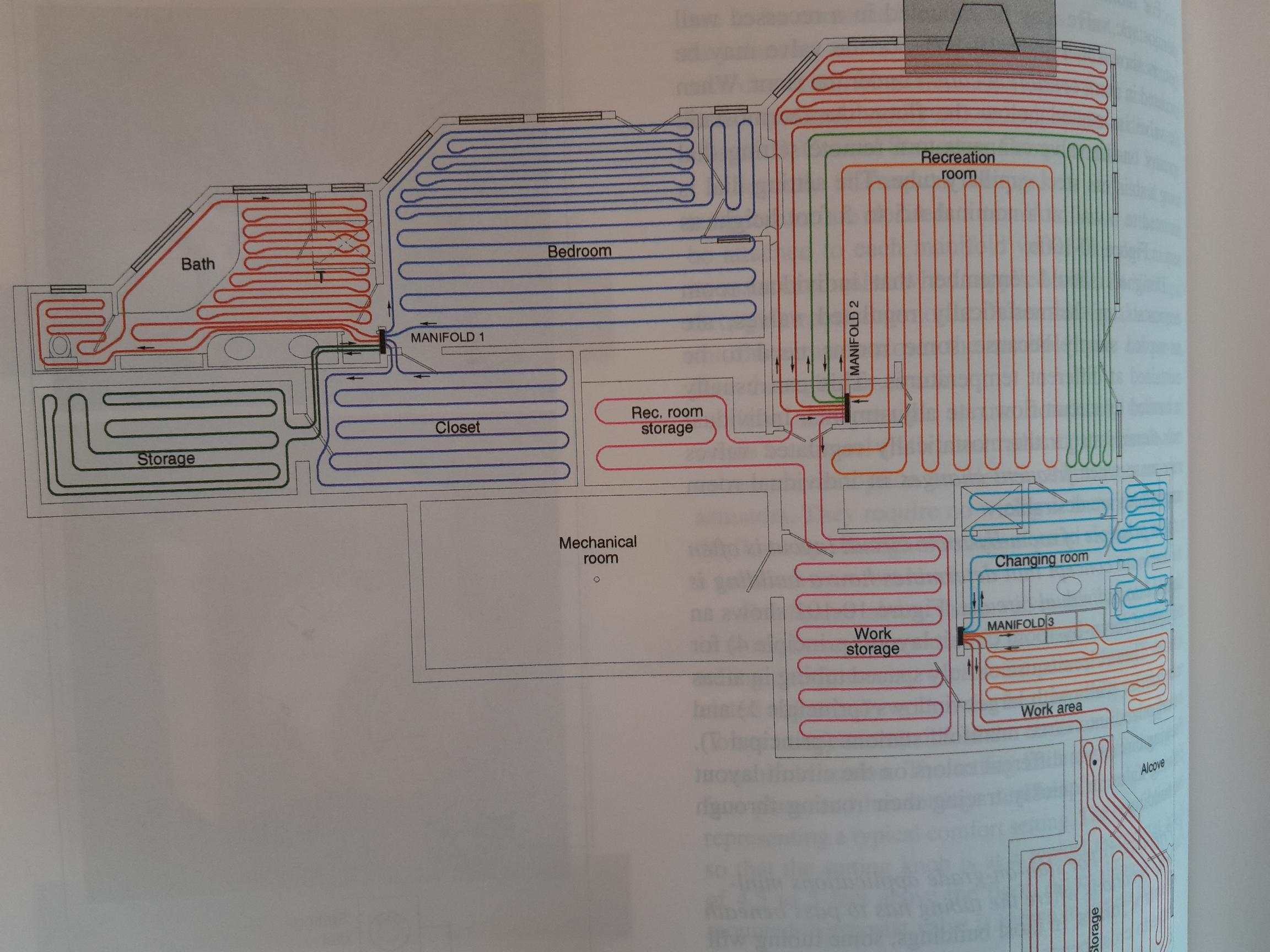
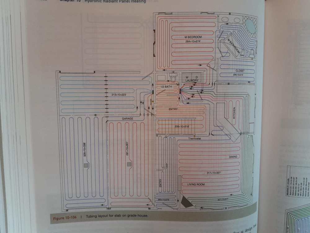
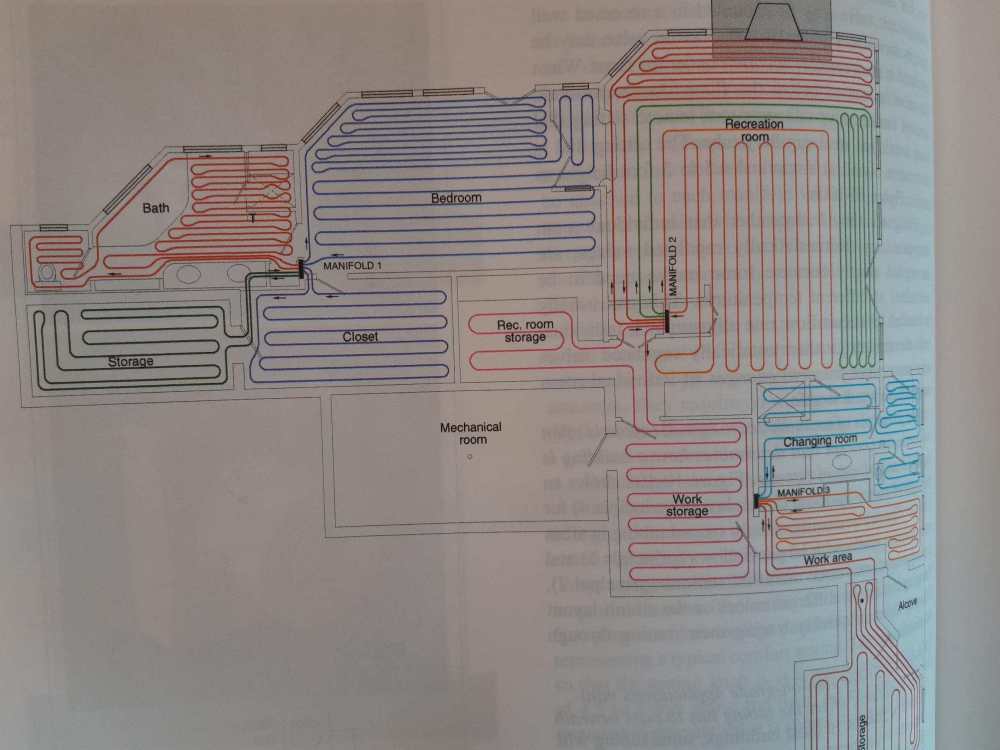
Yes, so the paper manuals and guides I used for all my basic training are (no great thermodynamics knowledge needed with these, thankfully 🙂). The underfloor heating design has lots of tables to referencing outputs and floor temps etc. and dovetails in the the CIBSE industry guide for sizing and designing heating system. The low temp guide has lots of easy win nomographs which can save a lot of time for ballpark figures: This links into the above question. As the output of the floor depends on pipe spacing, it seems weird that we can just discount that in design and just not worry about it? Output depends on the balance of several factors, including spacing flow rates and flow temperature all together. The calculation regarding the output of buried pipes is actually quite complex calculation, simplified here in this image: If you have significant transfer across the centre lines, then you're going to have problems with the balance of system output. Here is some images from a much more detailed hydronic books, which illustrate correctly varying the pipe spacing - look for example at where the spacing it closer at certain external parts of the rooms (this is also covered in the ufh design book above but to a much lesser detail: These and the illustration of pipe centre lines are from Modern Hydronic Heating & Cooling by John Siegenthaler. It has a very detailed section of UFH design, but the book costs nearly £100 and it's all in imperial so you need a way of looking up the metric constants etc. for SI unit conversion. HTH


-
UFH Design - LoopCAD, Heatpunk,Spreadsheets & Copilot
SimonD replied to Adrock's topic in Underfloor Heating
That's a good point. You always need to know the full load the pipework is going to carry as well as pump curve and heat pump drop offs. I always get these from manufacturer technical as part of a design if it's a new product for me. So to illustrate in @Adrock's situation. Lets for arguments sake say the output of the heat pump is 6.5kW in DHW mode. That same 22mm pipe, still assuming a total length of 30m (which it probably won't be as this pipework includes the section to the ufh manifold) This time I've adjusted water temperature to a conservative 40C. The figures are: Pressure drop: 19.69 kPa (2.01 meters head) Flow rate: 0.311 l/s Velocity: 0.97 m/s So the velocity is almost spot on for copper design purposes and you've got a doubling of the pressure drop, but if there's sufficient residual head at the pump, this should be no problem at all. My calcs include a 20% addition for fittings and if I remove fittings it drops to 16.40 kPa (1.67 meters head). If you used 25mm MLCP you could probably do the run without many fittings at all. So even in this scenario, providing there is sufficient residual head, which their should be from a decent heat pump as the pumps are now getting pretty big, even with DHW you're very well within a comfort zone. If I take this to 28mm. Pressure Drop: 5.69 kPa (0.58 m head) Flow rate: 0.311 l/s Velocity: 0.58 m/s So here, you're only just within the 0.5m/s velocity limit on dhw. As a real world example, I have one heat pump with a 6.5kW output at -5 installed with about 15m of 22mm polybutylene push-fit pit as the owner did not want to rip it all out and upgrade due to the extent of works required through the house. Yes, it's on the flow velocity limit of 1.2m/s on DHW but there are no issues at all with flow rates or function and efficiency is extremely good. The question is whether you want to incur the costs of 28mm pipework and a low flow velocity regime when for the vast majority of the time flow requirements are going to be nowhere near. -
water pipes underfloor: conflicting advice: help sought.
SimonD replied to saveasteading's topic in Barn Conversions
Sorry, that's difficult to say. I've got accounts with a few companies that have websites but they don't necessarily list the products on the site, you've got to call them to order the stuff in. Some of these are trade only. But most decent plumbers merchants, and especially renewable wholesalers will be able to cater for this as it's becoming increasingly common for this pipe to be used for heat pump installations. The water regs website is good, but it's not the complete reference. My reference is this dog-eared manual that's been seconded to drinks mat duty on occasion that you get when you complete your WRAS qualifications.
-
water pipes underfloor: conflicting advice: help sought.
SimonD replied to saveasteading's topic in Barn Conversions
Nothing wrong with exceeding expectations. It should be the norm really, shouldn't it? Glad to hear you've found your solution