MortarThePoint
-
Posts
2198 -
Joined
-
Last visited
Everything posted by MortarThePoint
-
DPC above wall plate on parapet
MortarThePoint replied to McCracken's topic in Bricklaying, Blockwork & Mortar
Could a liquid DPC be an option that gives better bonding to mortar? https://www.toolstation.com/damp-proof-membrane/p10290 -
We all know Superman is a bit of a voyeur so it's good to know Knauf Performance Plus plasterboard has "X-ray resistance" https://www.insulationshop.co/12.5mm_knauf_performance_plus_1200_x_2400.html
-
Large 2 part window installation
MortarThePoint replied to MortarThePoint's topic in Windows & Glazing
Got it in. It was a squeeze as I had made a measurement mistake but it is in and looking good ?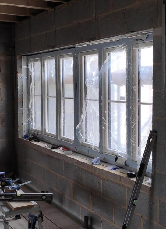
-
Thinking more in terms of walls, but it is a valid point. It's frustrating as I can see a few walls where I'd happily pay the extra £8/sh, but has to be sourced as a full pallet (38no. 2.7m sheets). Fischer have an interesting test report. Comparing various board performances with a HM5X52 fixing: 12.5mm Wallboard 0.6kN 15mm SoundBloc 0.75kN 15mm DuraLine 0.85kN 15mm FireLine 1.1kN In those last three board types and that fixing they conclude safe working loads over 0.2kN which is 20kg. "According to the Construction Fixings Association guidelines; “Ultimate load tests should be carried out and admissible loads (Safe Working Loads) determined according to the manufacturers technical policy.” For fischer this requires a safety factor of 4 for steel fixings and a safety factor of 7 for Nylon fixings."


-
Just saw this video comparing Habito, Duraline and standard plasterboard for impact resistance. Makes me want Habito even more, but it's 60% more expensive than Duraline and pallet quantities, so it's hard to justify.
-
I know you can use either wafer head screws or a stud crimper to joint metal frame together, but wondered what people actually tend to use. I like the idea of the crimper not leaving heads that stick out and the plasterboard has to go over. What do the pros use? @Conor looks like your MF contractor used some wafer screws, but did they use them through out or also use a crimper?
-
It's to keep the option of opening that area up and having it more open plan. There is a steel there so no need for a load bearing partition.
-
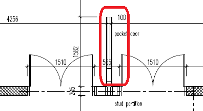
Do you mean the bit of wall circled in red. I may remove this from the design.
-
I might have some so that's a good thought.
-
I need to construct a shot section (565mm) of stud partition between two sets of doors. The blockwork either side of these doors is 190mm, thick, so I need to use substantial studs. I suppose I could use two lots of 90mm MF c-studs right next to each other. The wall circled in red below has a pocket door in it and I'm thinking of not having this wall altogether. That means the pillar sits isolated, so needs to be quite strong hard to resist the forces from the doors. The sole plate will be glued down and the header above the doors will go across to the blockwork. Which do you prefer the sound of: 2layers of 90mm c-studs 1 layer of 146mm c-studs with extra sheet of plasterboard each side. 7x2 timber
-
Large 2 part window installation
MortarThePoint replied to MortarThePoint's topic in Windows & Glazing
Great, I have a bag of ones similar to those as well. https://www.amazon.co.uk/gp/product/B07NWMCDVP/ That type is often described as glazing packers and used between the glazing unit and the sash frame, but should be good under the cill too. -
Large 2 part window installation
MortarThePoint replied to MortarThePoint's topic in Windows & Glazing
Thanks. Just standard frame packers like pictured below? I'm so used to beds of mortar under wallplates that it always feels like a nice way of spreading the load https://www.amazon.co.uk/Draper-44006-Plastic-Packers-Pieces/dp/B001233ZJC/
-
Large 2 part window installation
MortarThePoint replied to MortarThePoint's topic in Windows & Glazing
I found the information below in another one of their documents. This looks good for installing in sections. Any idea what the material I have circled in red is? It's not something the windows have come with and I presume it is something slightly compliant to avoid pressure concentrations.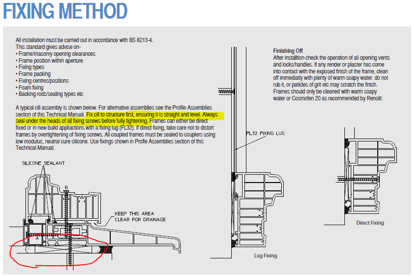
-
Large 2 part window installation
MortarThePoint replied to MortarThePoint's topic in Windows & Glazing
Thanks. It's on the first floor above a void unfortunately. We'll make a small scaffold for it, but may need to enlist some more hands unless we can work out installing in sections. -
Large 2 part window installation
MortarThePoint replied to MortarThePoint's topic in Windows & Glazing
As far as I understand it they even have hinges, but I may have got the wrong end of the stick -
Large 2 part window installation
MortarThePoint replied to MortarThePoint's topic in Windows & Glazing
With the Residence 9 flush casement system dummy sashes are actually normal sashes without handles and there is apparently a trick to opening them. -
Large 2 part window installation
MortarThePoint replied to MortarThePoint's topic in Windows & Glazing
Thanks Craig. I think the glass may be bonded in so could be an issue removing the glass. If I remove the sashes I'd be worried keeping it all just so (e.g. super square) so the sashes can go back in OK -
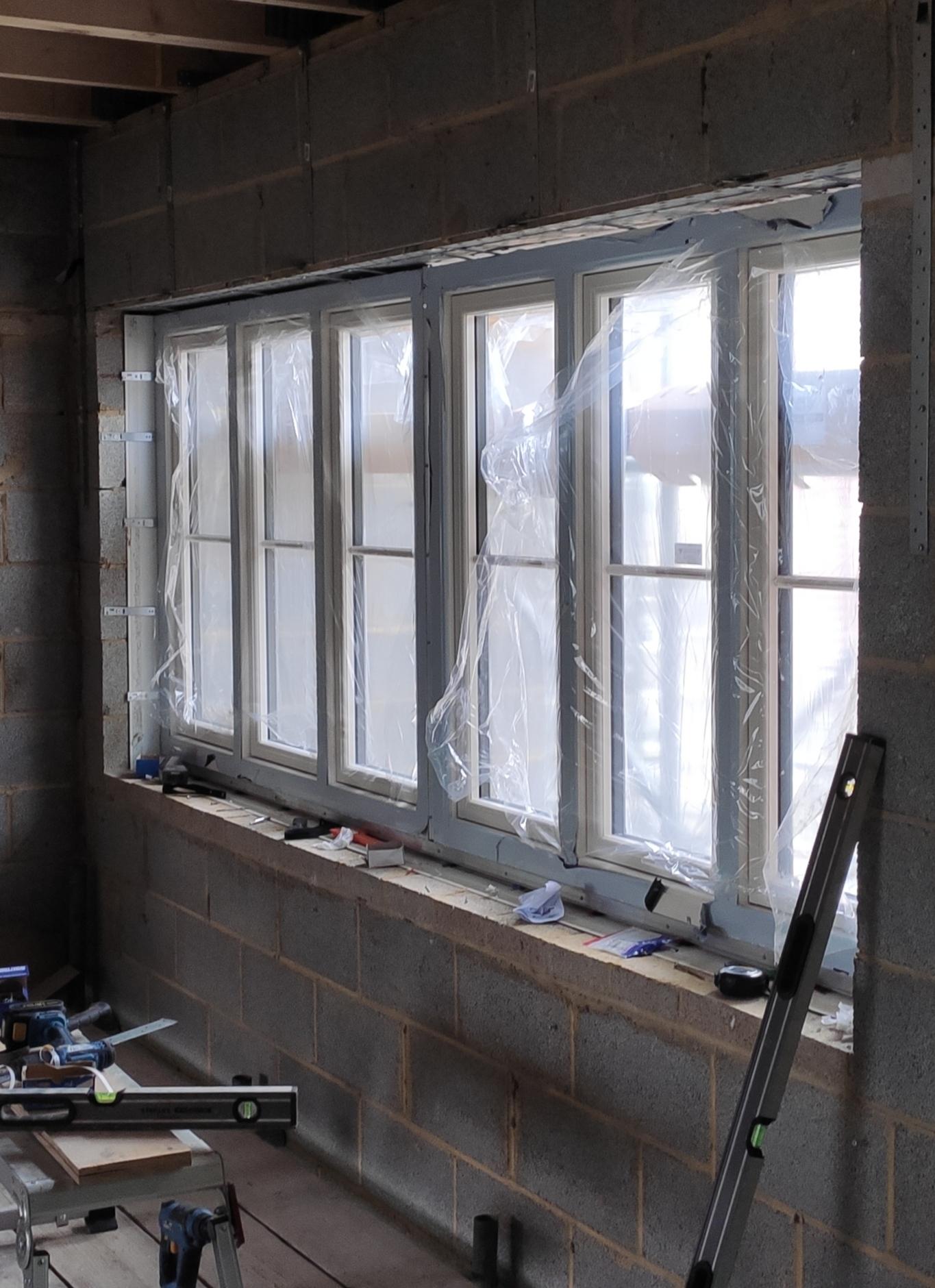
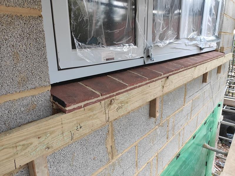
Most places I am using tile cills, but not in a couple of pleases. One of those is a 3.3m width by 1.3m high window that is made up of two frames coupled together, but a single cill running underneath. I'm wondering how to install this. This is heavy 100mm PVCu frames (Residence 9) with glass already in. Normal practice is to stick the cill to the frame prior to installation, but I'm not sure that makes sense. Possible approaches: Couple the two frames together and stick the cill on prior to installation of the whole lot. Heavy and hard to handle Attach one window frame to the cill and fit like that, then stick the second window frame to the cill during its installation Somehow install just the cill (drill and screw?) and then install the two window frames afterwards, sticking them to the cill Any tips gratefully received. I don't think the first option is practical given the weight and that it's just two of us installing the windows with their glass already in.
-
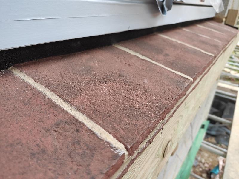
Well I'm no expert, but I am improving. Here's my fourth cill. My first three were in a group done together and smudged a bit unfortunately. Should have waited longer with those before jointing up.
-
That page only covers the ridge abutment and stepped flashings though.
-
Ouch! I presume you are more keen on chasing in lead at an angle if it is to be under render. If so do you have a spec for the thickness of the lead strip? 100mm?
-
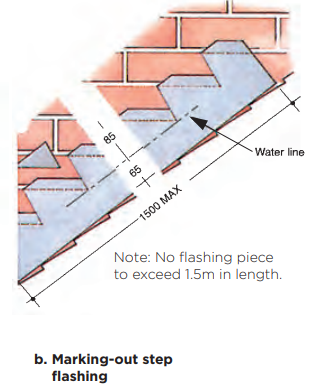
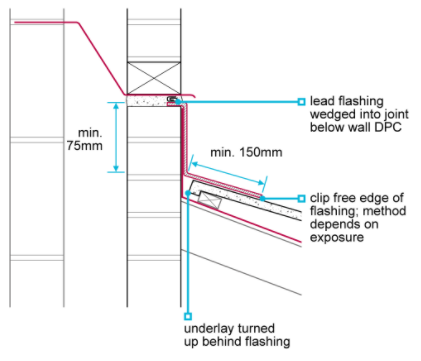
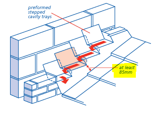
NHBC shows a stepped Flashing going as close as 65mm minimum to the tile line. The first link below shows older NHBC guidance which said 85mm minimum but that seems to now be 65mm. This is all for stepped flashing. I can't find anything for chased in at an angle but some logic (dangerous) dictates: Could be 85mm (or 65mm) measured across the flashing (e.g. 110mm tucked in ~25mm) Could be 150mm measured vertically which on a 45 degree wall is 106mm across the flashing Normally wouldn't be so fussed and they've used 150mm lead chased in (now). Above the bay window on the front of the house I want it tighter and fancy 100mm across the lead. Does anyone have a copy of the LSTA Complete Guide and able to see if they specify something for straight chased flashings? I know NHBC aren't building regs, but I haven't seen a building reg related to this and the warranty providers must meet or exceed regs (surely). I think a lot of roofers just have 150mm minimum in their head as that works pretty much everywhere. It's 75mm minimum lead upstand at a horizontal pitched roof abutment. https://nhbccampaigns.co.uk/landingpages/techzone/previous_versions/2011/Part6/section1/default.htm https://nhbc-standards.co.uk/7-roofs/7-2-pitched-roofs/7-2-20-weathering-details/ https://www.associatedlead.co.uk/wp-content/uploads/2018/06/Guide-to-Rolled-Lead.pdf


-
I've come back here after however many months and it's time for the roofers to tuck in their lead. Still think yours looks very nice. Looks like the vertical height of the flashing is about 130mm so at 45 degrees was it a 100mm strip of lead tucked in around 10mm? [90mm/COS(45) = 127mm] Or have you tucked it in much further ~50mm?
-
Nice idea, that hadn't occurred to us
-
It will be for occasional use. You have to walk past the intended back door to reach these doors.