MortarThePoint
-
Posts
2168 -
Joined
-
Last visited
Everything posted by MortarThePoint
-
RCBO for Mitsubishi Ecodan (11.2kW)
MortarThePoint replied to MortarThePoint's topic in Consumer Units, RCDs, MCBOs
Given how hard it is to find Type F RCDs or RCBOs from sensible places I'm doubtful the majority of people are using them. CEF list a 40A type F RCD for £160+. That's about all I've found -
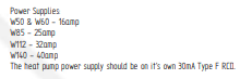
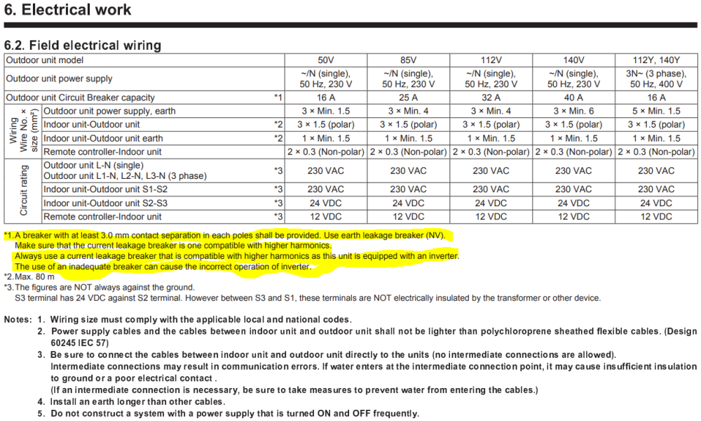
The schematic of my ASHP system design calls for a "30mA Type F RCD". I think that's out of date now and would need to be an RCBO. What type of RCBO do I want to use for this? Type / Curve and how do I reflect the "Type F RCD" requirement? From Ecodan Installation Manual:
-
What do you do at reveals when doing sand and cement (S&C) plastering on walls? Do you line with plasterboard as normal and then skim over both the S&C and the plasterboard with MultiFinish?
-
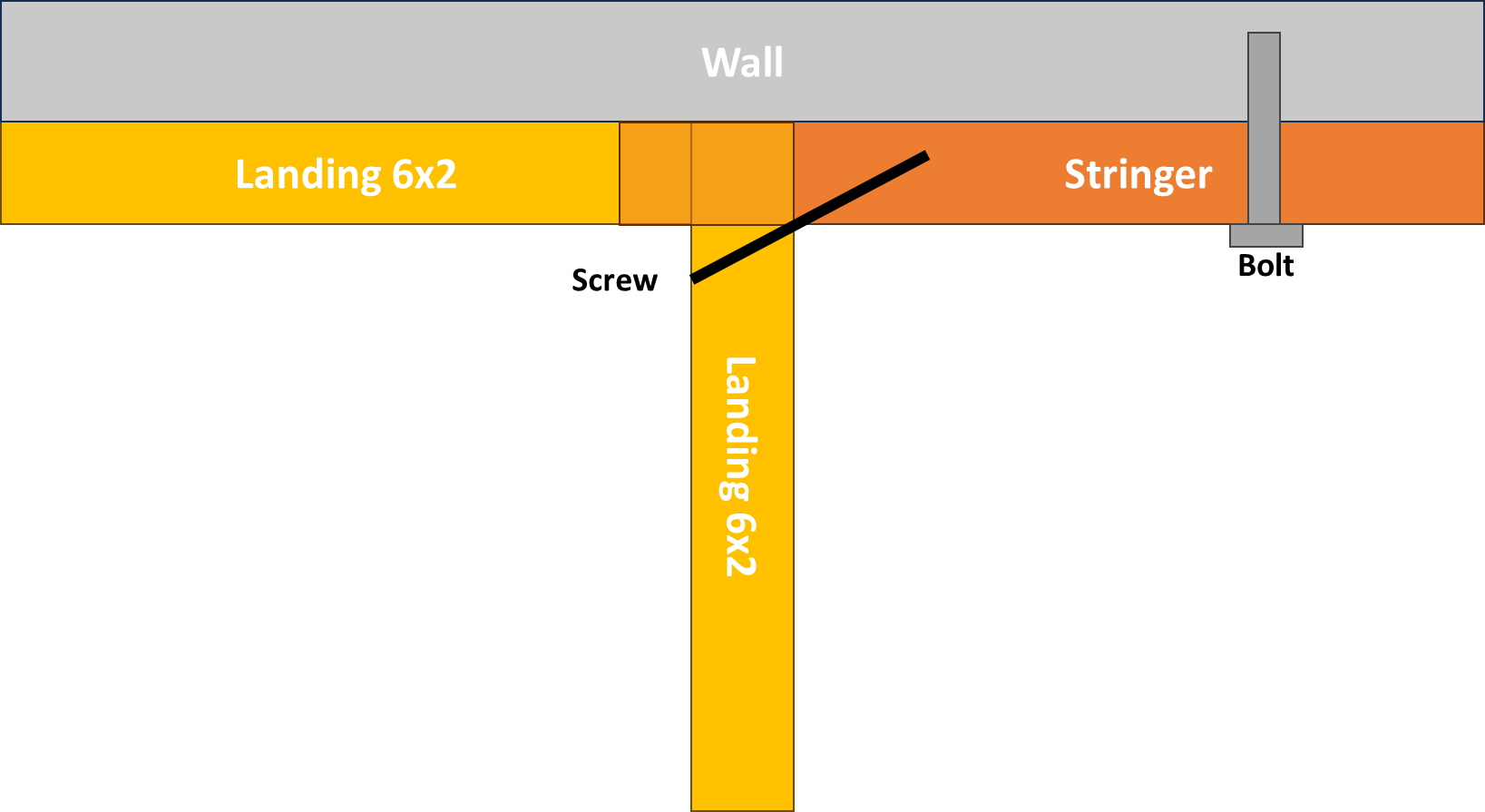
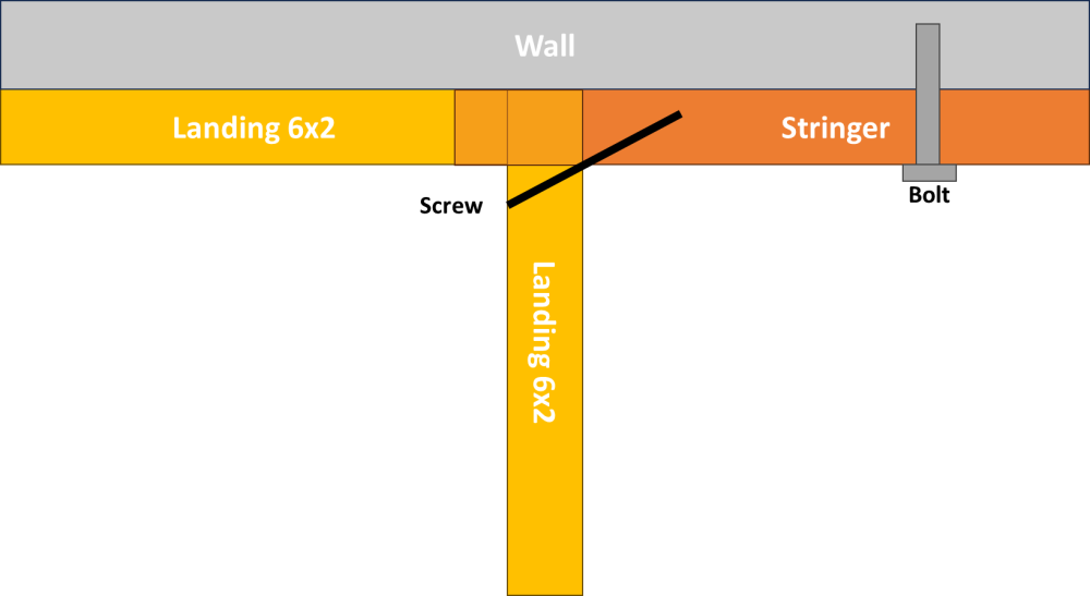
The 6x2 of the landing against the wall was presumably in line with the stringer, so did you toenail it through the landing's front 6x2?
-
The picture hasn't uploaded for some reason
-
What type of metal bracket? A CAD drawing would really help if you are able to.
-
How did the it attach to the half landing?
-
I'm interested in how the right hand stringer is mated to the skirting board at the top. Do you have a close up of that?
-
I want to do the whole thing myself and have the satisfaction, but the newel to stringer m&t joint is intimidating.
-
It's the beginning of the end for a business when it expects it's customers to bear the price of its poor management. A well trodden path sadly.
-
Stairbox are much more like it. £2800. Do they have are mortice & tenon newel to stringer connection?
-
If I cost up my staircase in parts, it works out as about £1600. I have just had a quote from the same company that supplies the parts and its £4500. I know there is work in the cutting and assembly, but it doesn't feel like £3000 worth. Without the CNC machines, it feels like it would take an experienced joiner 1-2 days to cut everything and then perhaps similar to assemble to the same state that you receive a staircase in. That means you're looking at perhaps £2400 compared to the £4500. Mass production should make the staircase manufacturer cheaper. What am I missing?
-
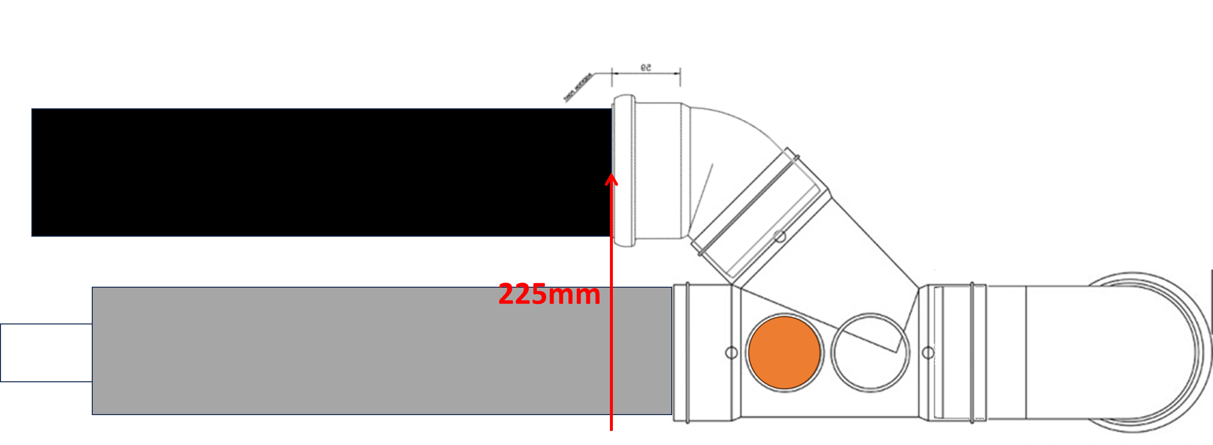
I might be able to do something a little similar passing the 50mm shower waste underneath the toilet 110mm and the having it change to 110mm for about 500mm before the using a Y on its back. A challenge is that the Toilet pipe ends up centred about 225mm above HCF at the junction so with the about 2.0m of run that makes it 225mm + 2.0m * 18mm/m = 261mm. A bit more to allow fall between Y and the 90 bend exiting the room makes for 270mm. If screed is 60mm and if tile adds 10mm that would put the pan connection at 270 - (60 + 10) = 200mm above tile which is about 20mm too high for most toilets. Closer than I feared it might be though. The bath pipe could offset vertically near to the boss so as to slop flow towards the bath. Can I be sure the boss wouldn't get blocked with poo?

-
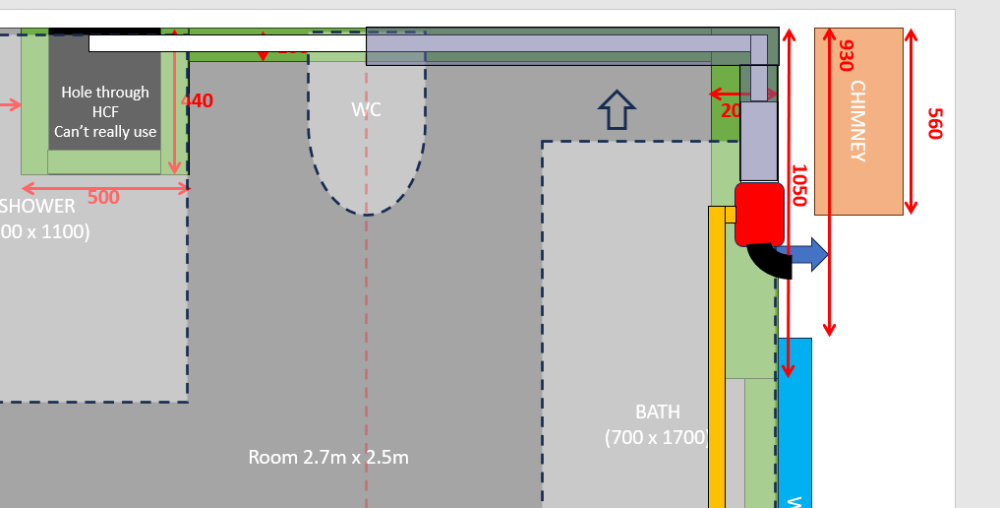
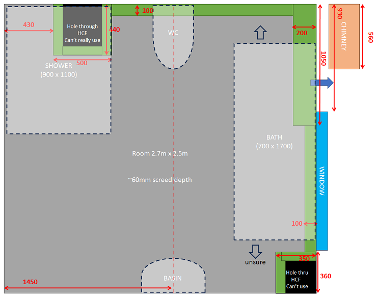
In terms of the whole room, here's what I am up against: Room 2.7m x 2.5m ~60mm screed depth
-
Cross post sorry, a good length of 110mm before the tee seems sensible. Not sure I can manage that though.
-
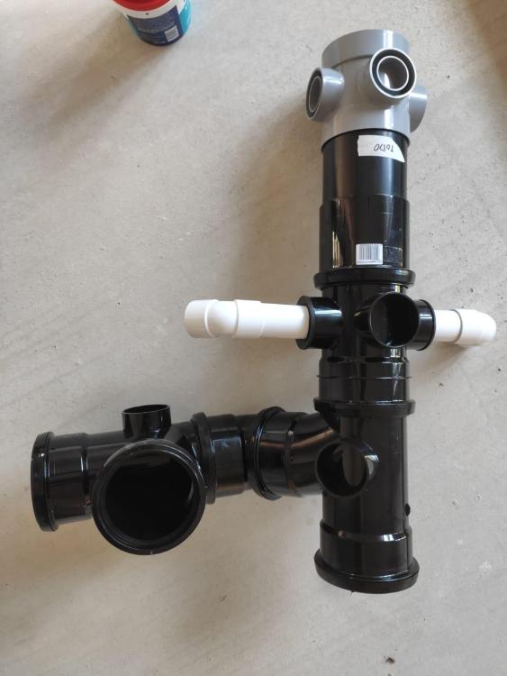
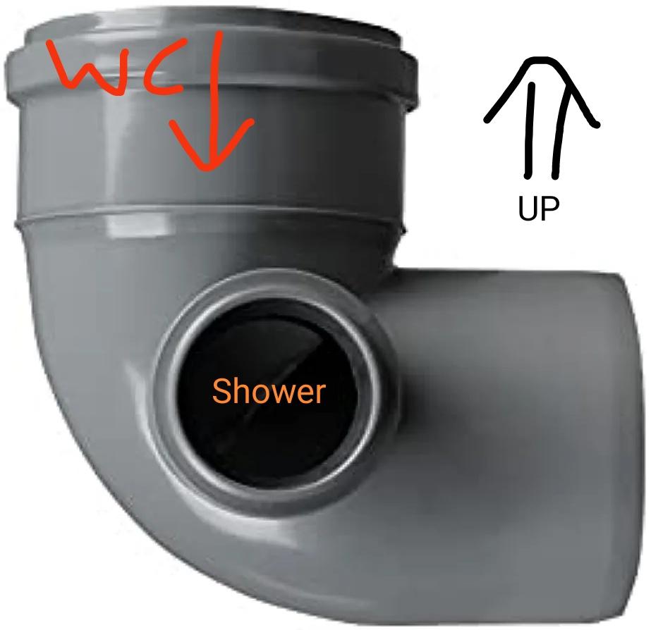
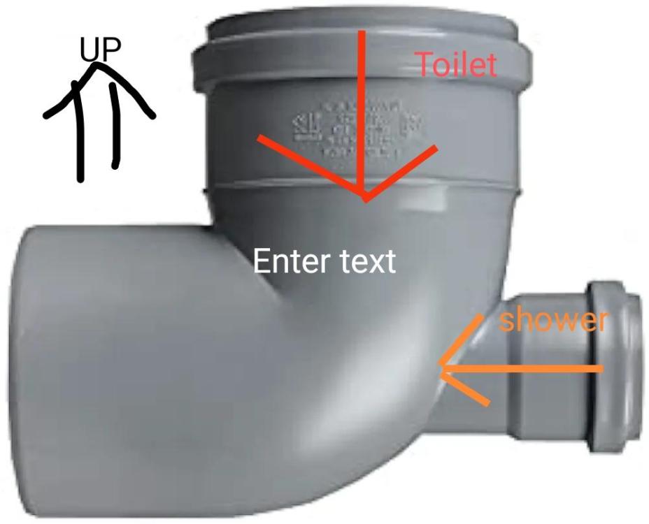
Are you thinking like one of these laid on it's back as shown here

-
No it is sold, eg on Amazon, and I can see how OK if waste pointed up
-
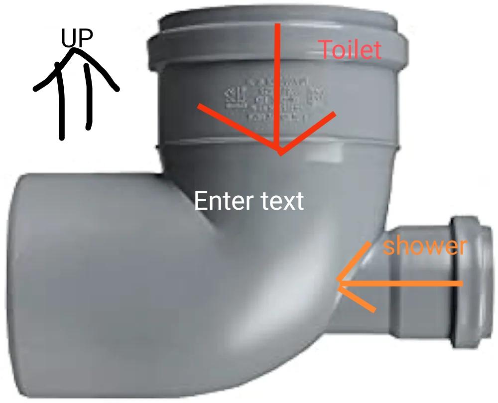
Pretty clear cut then I had concerns too, is this better

-
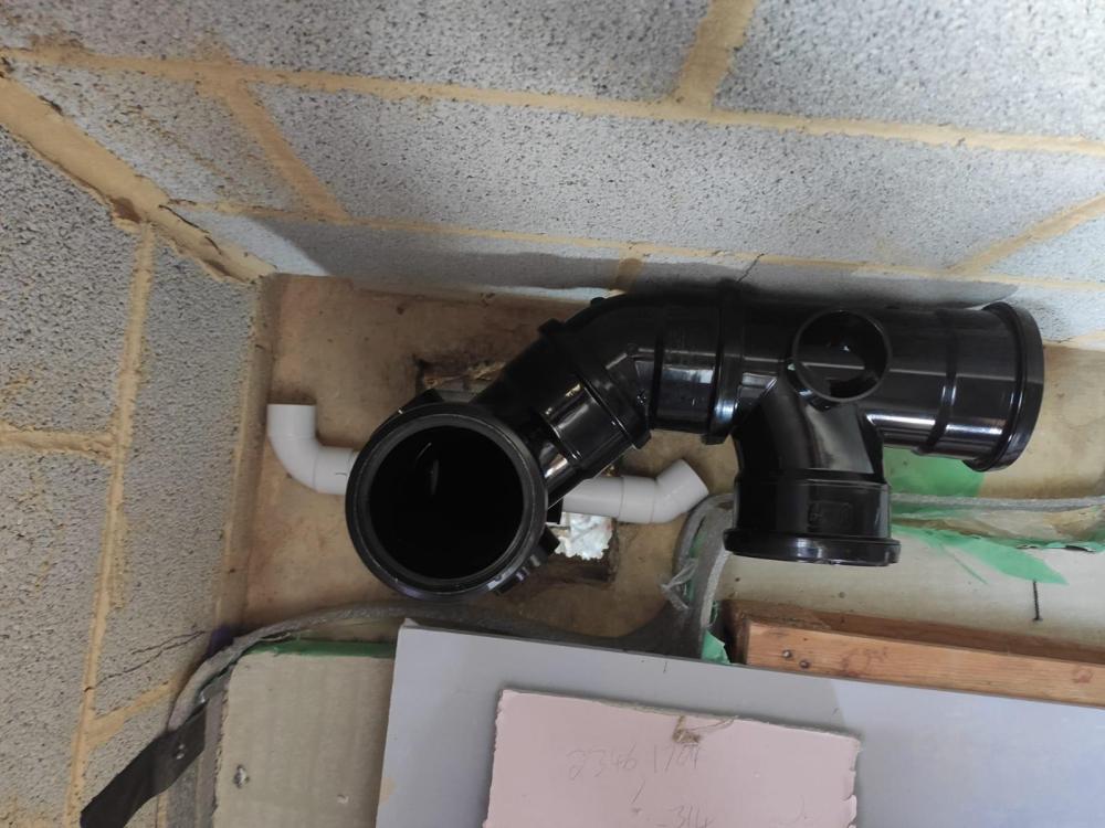
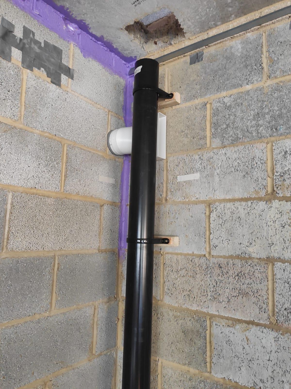
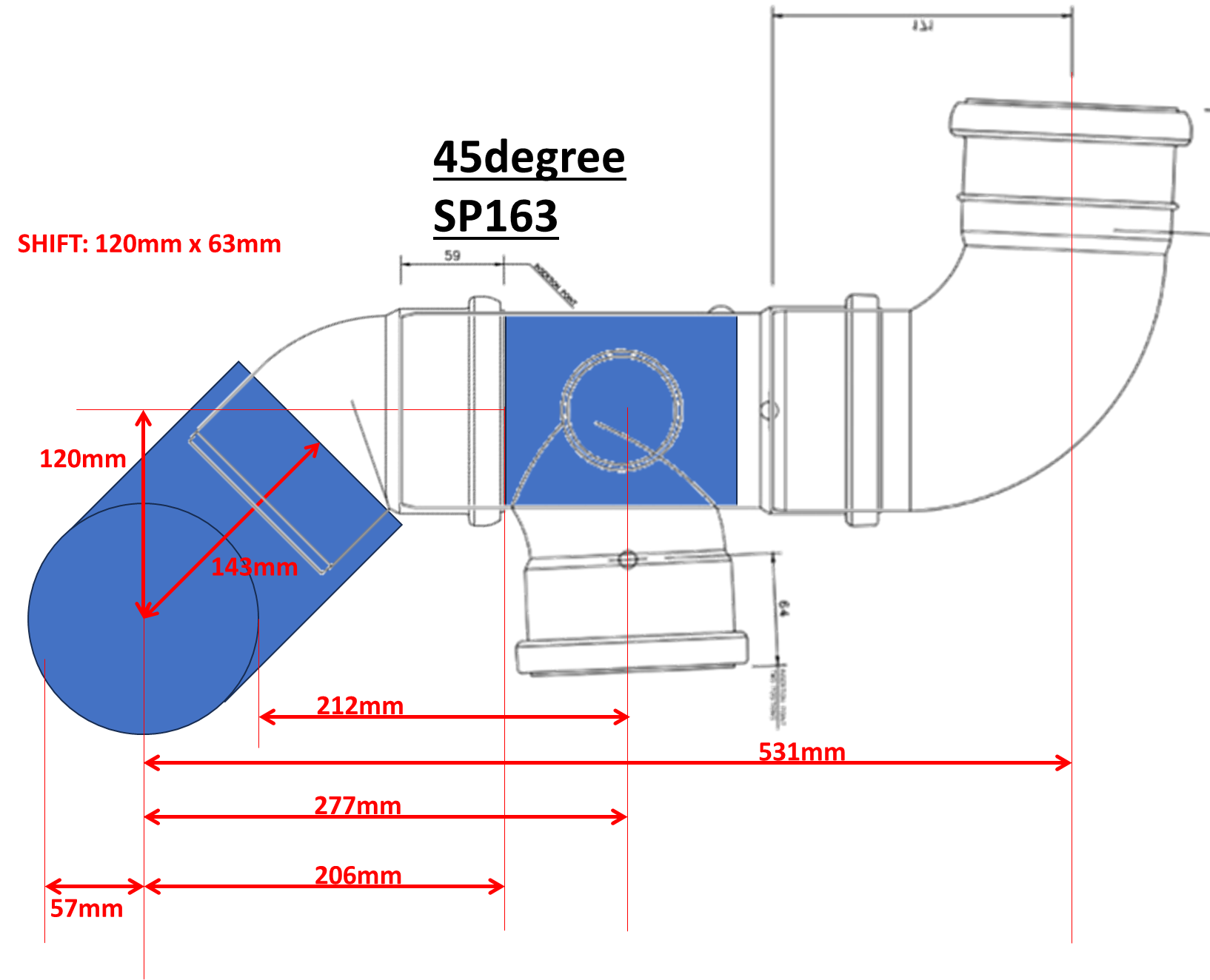
I need to get a toilet pipe and shower waste (plus others but similar principle) out of a room without passing much below FFL. My only thought is to do something like the attached image. It doesn't feel ideal, but is it a no-no? The exit of the bend would then pass through the wall and to a bend 90 heading down. I want to avoid joining the waste pipe the other side of the wall as that is outside and will increase the visual impact.
-
Staddle Stones vs Post Bases
MortarThePoint replied to MortarThePoint's topic in General Construction Issues
Why would it have to be big and flat. If anchored the staddle stone to the concrete pad and the post is anchored to the staddle stone I'd hope it can be something like 200mm x 200mm x 200mm. It would be better if I could find a rebar post anchor with a longer piece of rebar as then it could pass all the way through the staddle stone and be structurally connected to the concrete pad. I'd prefer something that doesn't end up visible, but I could bolt one of these to the top of the Saddle stone: https://tradefixdirect.com/post-supports/simpson-concealed-post-base-1-1 -
Staddle Stones vs Post Bases
MortarThePoint replied to MortarThePoint's topic in General Construction Issues
The post wouldn't be gripping the rebar so should there be some form of retention there? Something like the bracket below. It's rebar would ideally be longer if wanting to go all the way into the main pad. https://www.amazon.co.uk/support-bracket-adjustable-Terminal-90X130X8/dp/B01LZGXEPV/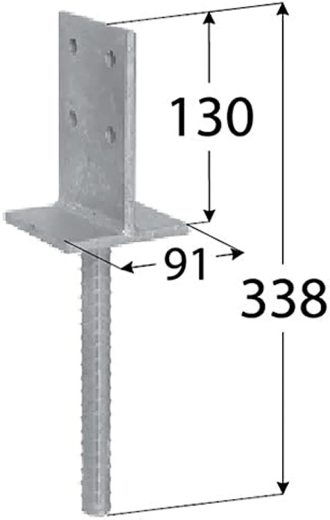
-
Staddle Stones vs Post Bases
MortarThePoint replied to MortarThePoint's topic in General Construction Issues
Looks like it's worth considering stainless a steel dowel: https://jbstone.co.uk/masonry-supply/staddle-stones/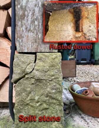
-
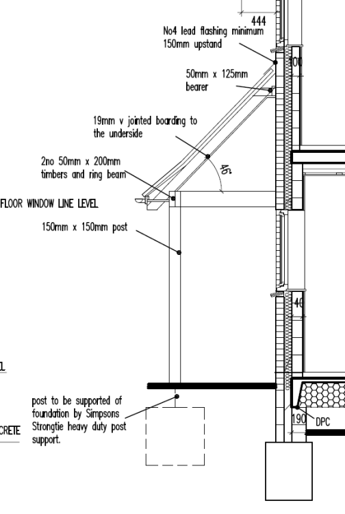
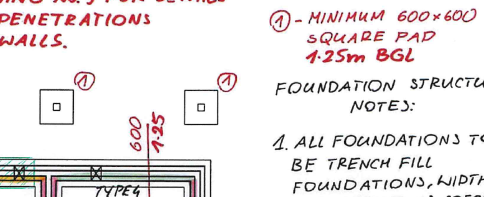
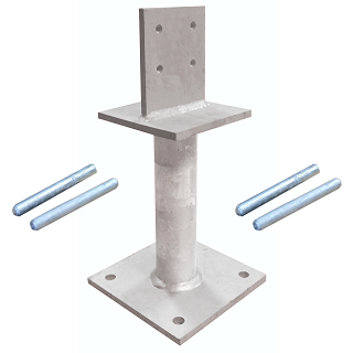
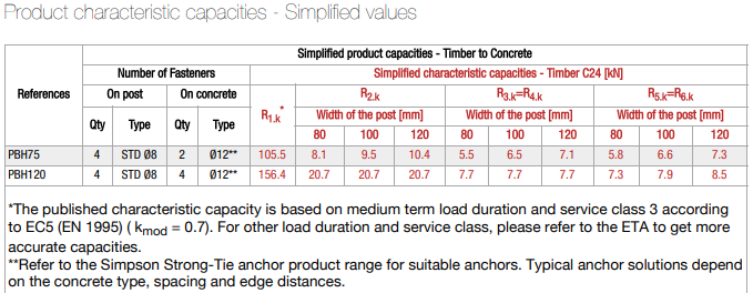
I'm building a Loggia across the back of the house and to this point assumed I was going to use a galvanised post base, and settled on PBH120 because it it higher than the cheaper PPA and PISBMAI alternatives. It feels like a good choice to have the bottom of the timber post >150mm above ground level to avoid rain splash in a similar way that having house DPC there does. I have cast 600mm x 600mm concrete pads on top of slightly larger pads that go all the way down to 1.5m. I have put the top of that pad 225mm below house DPC to allow: 150mm patio to DPC 50mm paving slab height [or 63mm] (could be thinner slabs on a deep (40mm) mortar bed 1:80 patio slope so based on 1600mm total patio width that yields 20mm. 5mm slack If using the Galvanised post base, the plan is to bolt them directly to the concrete pad and leave a 300mm x 300mm hole in the paving that I then fill with pebbles. I am a little worried that the post base may rust in time though, so that made me think of sitting the post (or even a shorter galvanised post base) on a concrete block of some sort. I have now learnt this is called a Staddle Stone and the post normally sits directly on this by means of a piece of rebar that is cast into the concrete block then sits in a hole in the base of the post. This seems like a nice approach. Discussions with @Gus Potter identified that I need to think carefully about lateral loads due to things like logs getting piled against the posts. I am not sure which of the R numbers in the table below of post base capacities reflects this direction of loading. How is this dealt with when using a staddle stone? It occurs to me that I could have a piece of rebar (e.g. T20 = 20mm dia.) passing all the way through the staddle stone and into a hole drilled in the concrete base. I expect I need a bed of mortar under the staddle stone and perhaps to resin the rebar into the concrete pad (and/or) staddle stone. Is that how it's done? Will there be enough lateral load capacity in such an arrangement though? The post may well end up being 150mm x 150mm Oak and I guess the rebar would pass into in about 75mm or perhaps a bit more. https://www.strongtie.co.uk/en-UK/products/heavy-duty-elevated-post-base-pbh
-
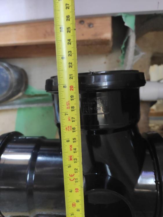
I drilled an oversized hole to allow a bit of wiggle and will pack it with acoustic roll when done. Flexible / offset pan connectors could give me extra wiggle room too.
-
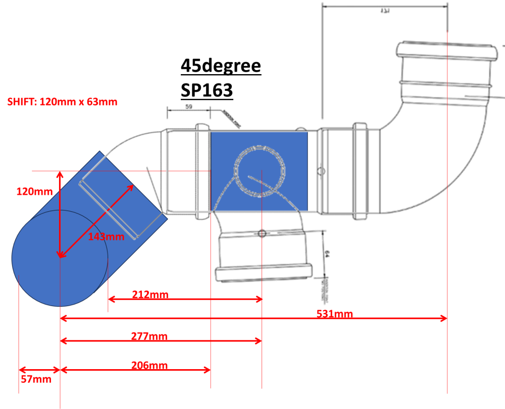
An adaptation to move it closer to the wall. 210mm + 36mm for a 20mm or 40mm Offset Rigid WC connector (or MACFIT 20mm / 40mm) and minus ~16mm for plaster and tile give >=230mm for back of cistern to wc connector distance. That may allow some close coupled, but certainly plenty of traditional style options. (a straight option is unlikely to work but is MAC-1 . About 200mm between the centre line of the loo in this room and the higher part of the box-in. That allows the pan to be up to 400mm wide at that point which is unusual (most narrower than that at their widest). Still another boss to use for a 32mm pipe. Also a second new boss to use below the floor for a 50mm shower waste.