MortarThePoint
-
Posts
2198 -
Joined
-
Last visited
Everything posted by MortarThePoint
-
Regulations for landing balustrade (banister)
MortarThePoint replied to MortarThePoint's topic in General Construction Issues
Can't get it in one length and prefer the look of it stopping at each post -
Regulations for landing balustrade (banister)
MortarThePoint replied to MortarThePoint's topic in General Construction Issues
What's the normal method of attachment between the intermediate post and the two sections of handrail? I'm familiar with the approach at a post that only takes a single handrail section where you can drill through the post and screw into the handrail end, but that wouldn't work with two inline sections of handrail. -
The plan is to use two 90x25 and two 40x25 timbers glued to make a 90x90 hollow square section. It's going to be painted and the narrower width timbers will be inline with the handrail and spindles so somewhat hidden. I'm thinking the 90x25 facing the landing will get screwed to the Unistrut at 200mm intervals to couple the timber to the metal. Alternatively, perhaps the 40x25 pieces as they don't stop at the top of the beam.
-
This metal post will be down the middle of a timber post that will add the vast majority of the strength of a solid timber post too.
-
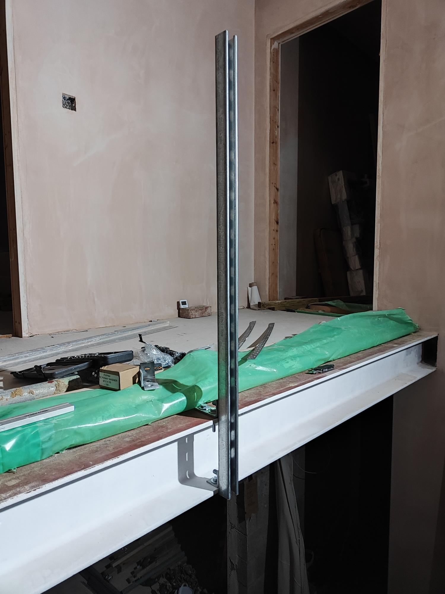
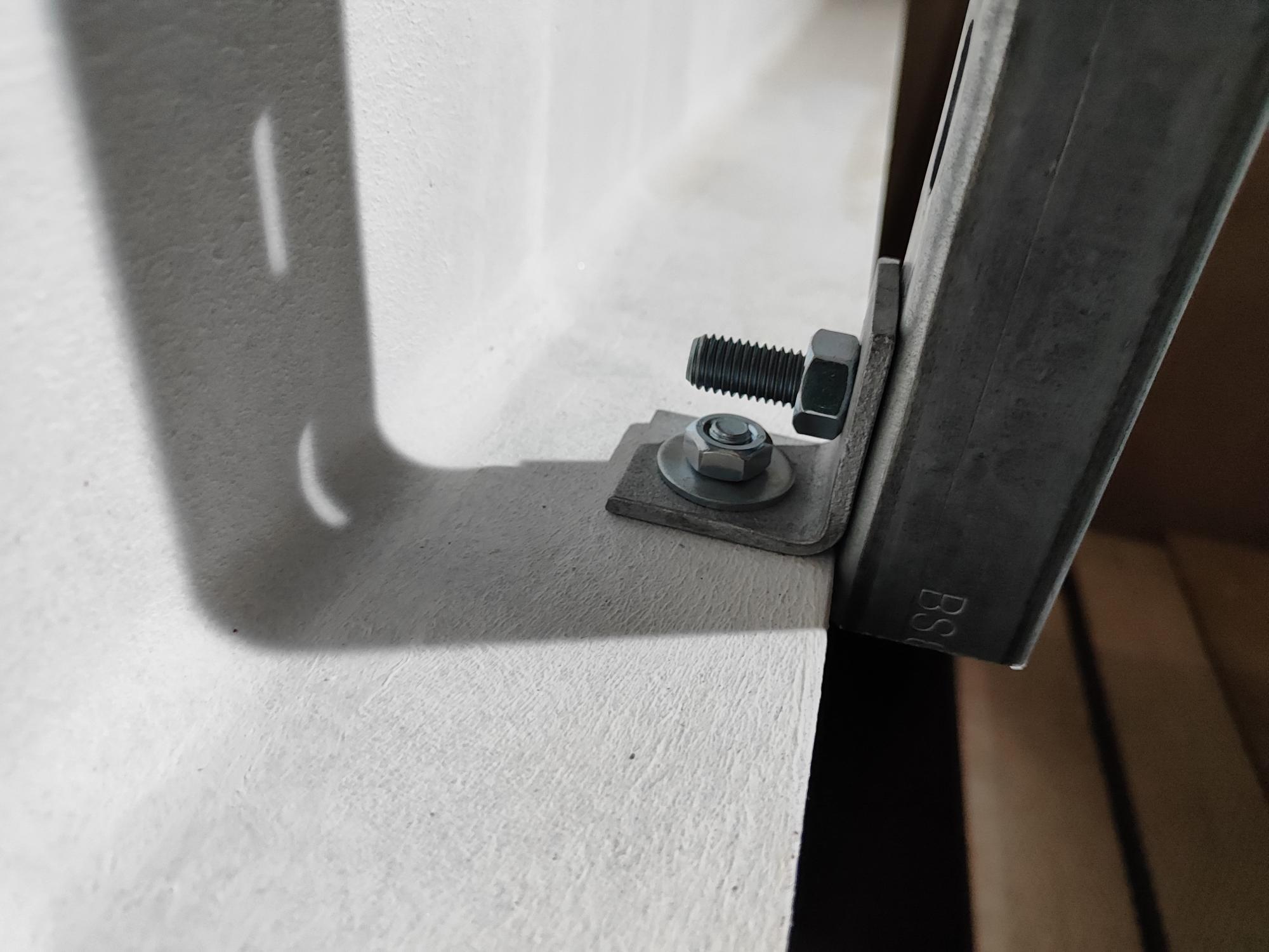
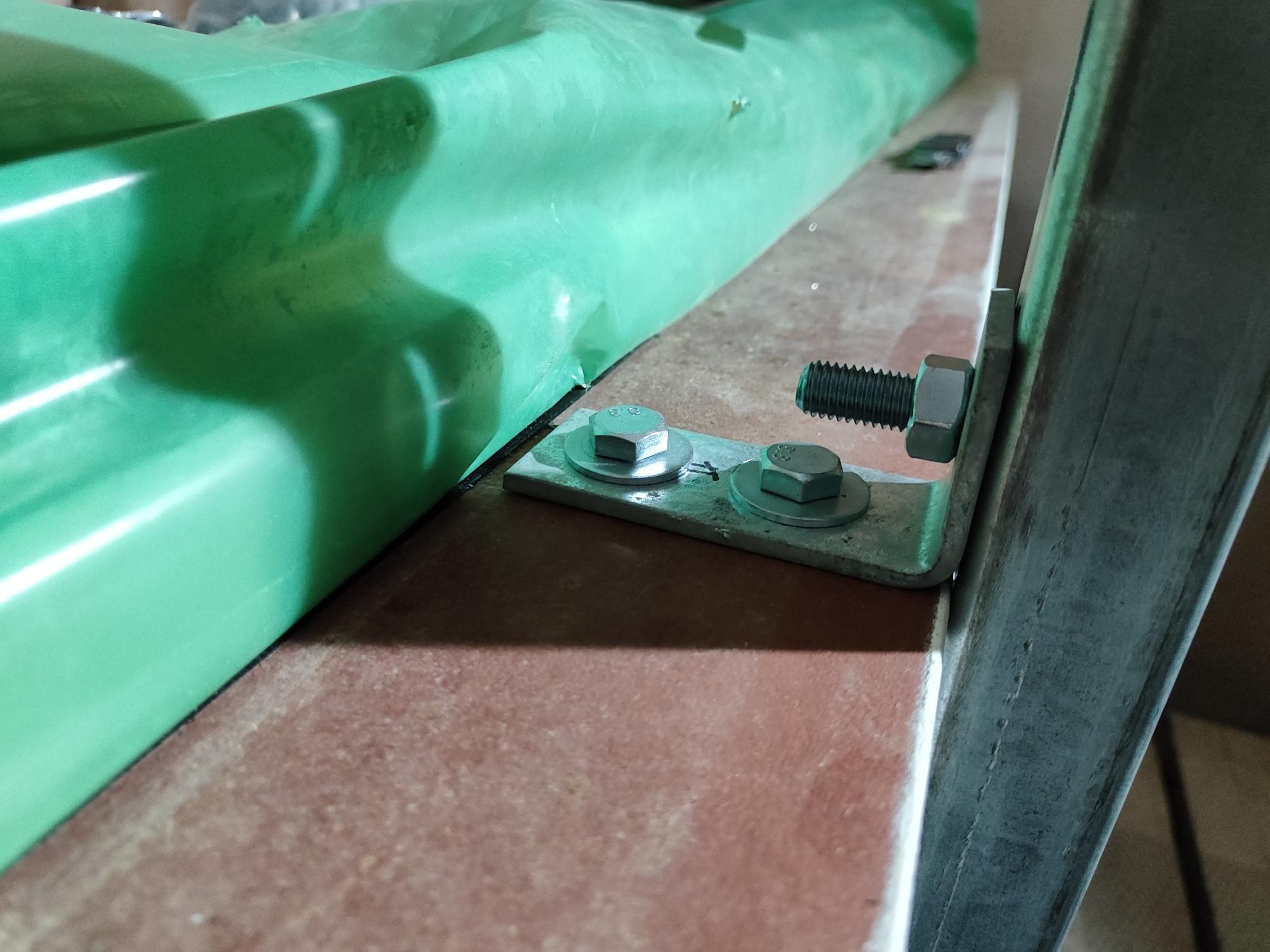
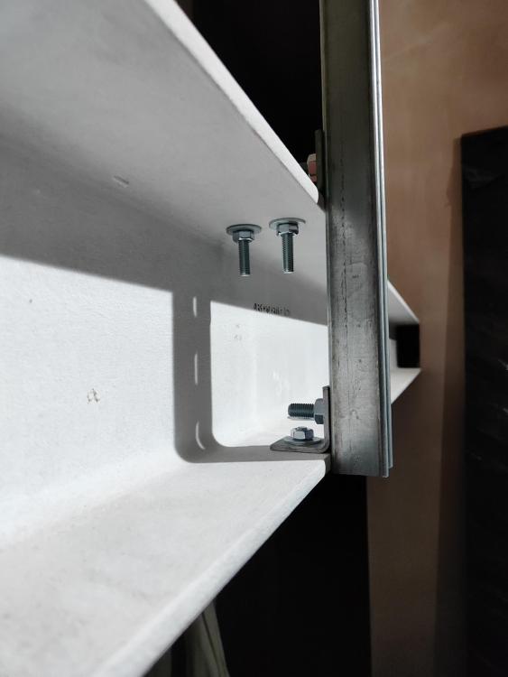
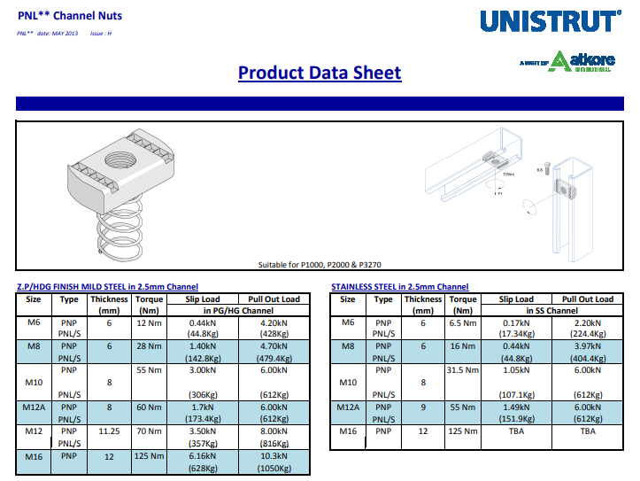
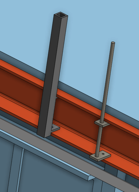
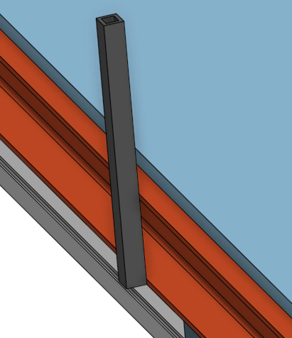
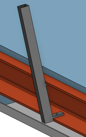
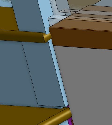
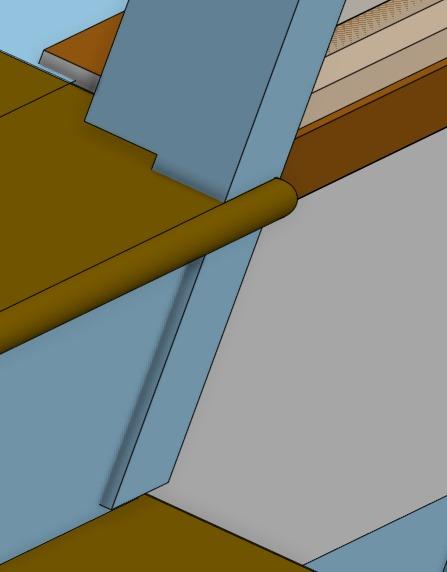
Here are some photos of the Unistrut in situ. It feels stiff. It extends 965mm above the top of the beam and to flush with the bottom of the beam. If a moment is applied to it equivalent to someone leaning on the handrail, the strut is pushed against the beam at the bottom and the top mounting is under tension. I used a top mounting that allows two M10 bolts (could upgrade to M12) to resist the shear and one M12 bolt in tension. All bolts are to be torqued, Loctited and doubled up. An exception to that may be the bottom mount's M10 shear bolt which doesn't really have room for a second bolt. The bolts are grade 8.8 so the M10 bolts have a shear strength of 22.3kN each and the M12 has a tensile strength of 48.6kN [https://eurocodeapplied.com/design/en1993/bolt-design-properties]. That means in terms of the bolts, the top mounting has a strength of 44.6kN. The strut acts as a lever to gears a force applied to its very top by a factor of (965 + 206) / 206 = 5.7. That means the bolt related strength would be 7.8kN before any safety factors are applied. @Gus Potter I know this isn't as beefy as your suggestion, but it feels solid. I could slip a solid rectangle section (e.g. 30x35) into the groove of the channel if I decide I want more strength. That could add up to another 79,000 mm^4 and achieve a total of 130,000 mm^4. However, I think the torsional strength of the 6.1m UC203x203x52kg may be similar to the bending strength of the 41x41x2.5 Unistrut. I could add a brace to the middle of the beam that couples it to the concrete HCF plank that is next to it which also spans 6.1m, but doesn't touch the steel beam. I think I'd rather not couple them though. I'm having two such posts which divide the balustrade up into three 1718mm sections. Discussions on another thread suggest 0.36kN/m UDL on the handrail which would make for a tip load of 0.62kN. That's well under the bolt strengths (~8%) and would create a Unistrut bending deflection of 17mm (L/57). It feels stiffer than that when I have applied a pretty large force. Any recommendation as to the required torques for the nuts?


-
Regulations for landing balustrade (banister)
MortarThePoint replied to MortarThePoint's topic in General Construction Issues
I was assuming a UDL of 0.36kN/m so total load of 3m * 0.36kN/m = 1.08kN -
Regulations for landing balustrade (banister)
MortarThePoint replied to MortarThePoint's topic in General Construction Issues
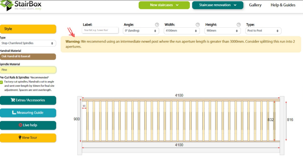
Interesting, so adding that to the Stairbox 3000mm figure suggests each newel has to be able to take 1.08kN. -
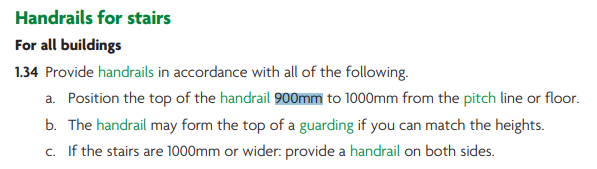
Other than height (900mm I think) I can't find any particular guidance on balustrades. It feels like there should be some maximum distance that a balustrade can be before it needs an intermediate newel post, but I can't find a regulation for that. Stairbox suggests 3000mm. Has anyone found a regulation that applies or has any guidance beyond what Stairbox say?
-
Looks like it's 6kN for a single M10 so if I used a bracket that allowed two M10 it would give over a ton of pull out strength What do you think @Gus Potter, could Unistrut be an option as it is super easy to work with and to source (e.g. TLC)? A lot less strong than 50x50x6 SHS (only 15% of the stiffness) but do you think it is 'enough'?
-
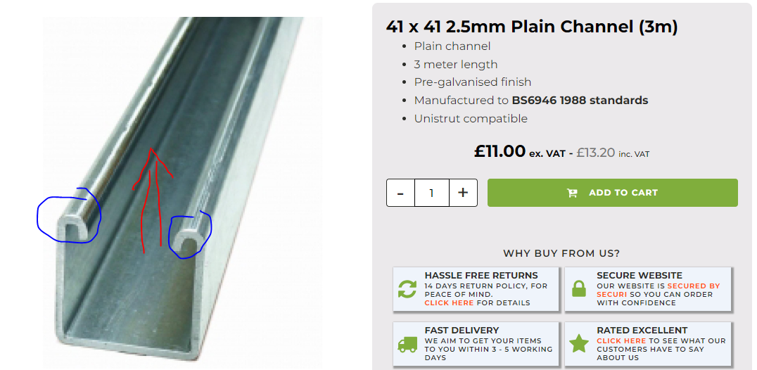
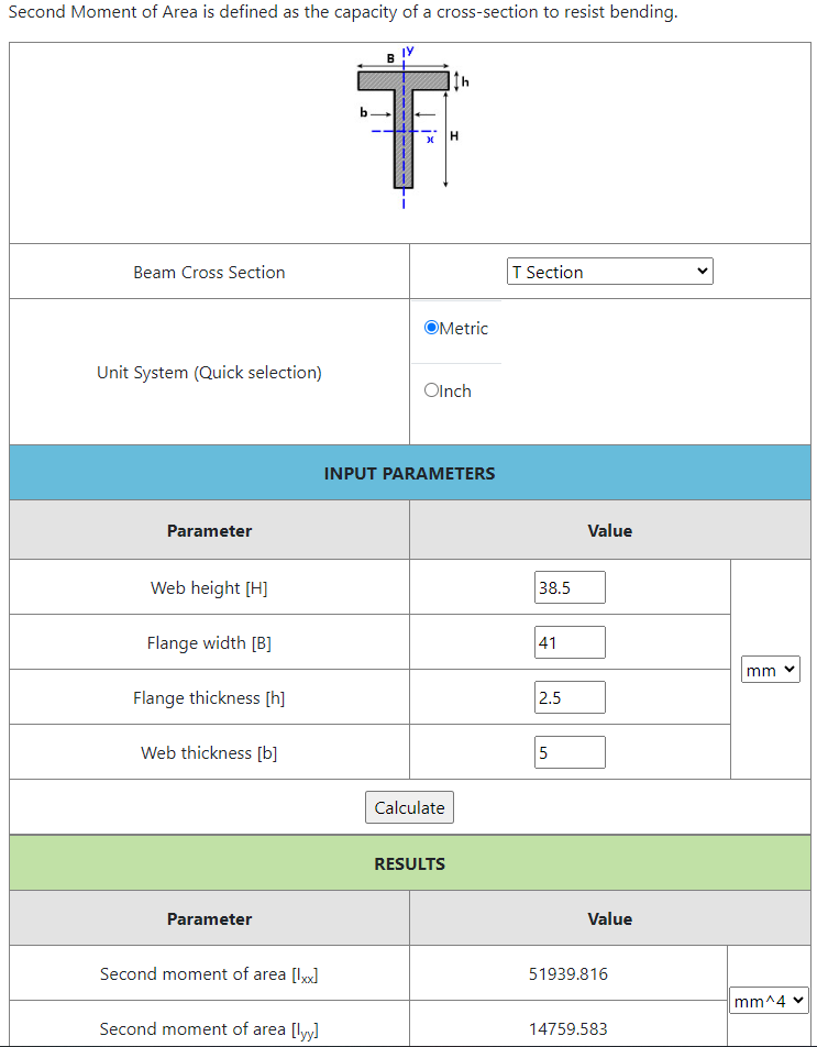
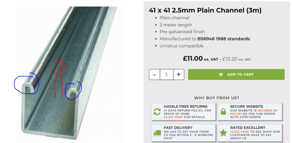
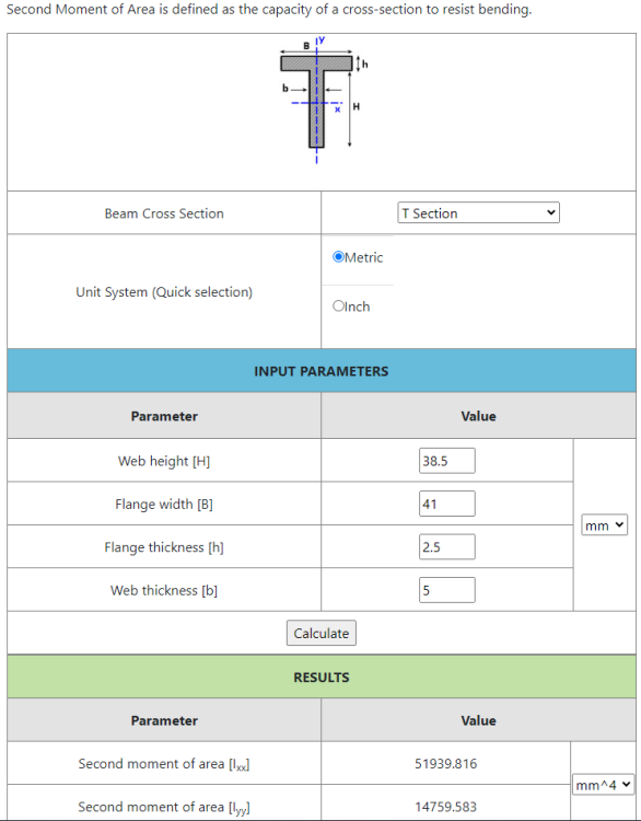
Unistrut steel channel looks like a possible half way house. It's 41 x 41 x 2.5 which isn't as stocky. It feels fair to model it as equivalent to a T section in terms of bending in a direction parallel to the red arrow (conservative since the parts circled in blue would add stiffness). The calculator gives a value for the second moment of area of 51,940 mm^4 which is 41% of the 40x40x5 SHS or 15% of the 50x50x6 SHS. That sounds like a massive downgrade, but the 1kN force at 600mm would give a deflection of about 6mm or L/91 which doesn't feel too bad for what is a pretty large force (100kg lateral force). If the mountings are 150mm apart, the force on the top mounting would be 5 times the load at the tip, so 5kN. I don't know how much force would pull out a T-piece from the channel.
-
Cutting a round hole in the timber post is easier than a square one. A 32mm piece of circular hollow section (CHS) with 4mm wall would have a second moment of area of 38892 mm^4 which is a quarter of the 40x40x4 SHS but would allow the use of a 32mm auger bit which is cheap. 1kN would bend it by about 10mm at 600mm cantilever. A 50mm CHS would be getting on for the 50x50 SHS but trying to drill a 50mm hole in a 90x90 post could be tricky to say the least. I may be able to outsource that though. I could mount a round tube against the flat surface of an angle bracket, but it would be nice to have something that mated to the curve.
-
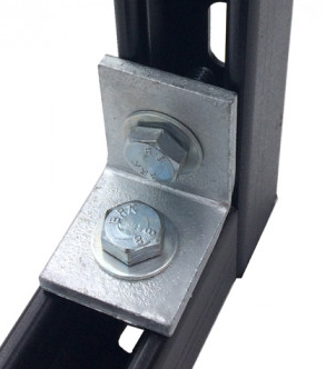
Actually, these look beefy: 90 DEGREE RIGHT ANGLE 1X1 HOLE - TYPE (P1026) - HOT DIP GALV. 53X41X5MM https://directchannel.uk.com/90-degree-right-angle-1x1-hole 14mm hole is a bit bigger than ideal but that could allow adjustment with M12 bolts
-
Instead of welding plate onto the 50 x 50 SHS could I use any form of angle bracket bolted to the SHS and to the beam flange. I would want it to be substantial and may not find anything beefy looking enough enough. I guess an alternative is to make a 'bracket' out of a short length of SHS laid on its side along the surface of the beam flange. Two vertical holes to bolt that to the beam flange and one horizontal hole to bolt it to the vertical SHS which is what I'm trying to mount. I could have one such short length of SHS on each flange. I wondered about some arrangement with U bolts, but that wouldn't work being sleeved by the timber.
-
Cross post, but same conclusion.
-
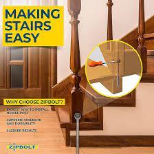
Using this calculator: https://calcresource.com/statics-cantilever-beam.html suggests a 106mm deflection on a 600mm long cantilevered 16mm steel rod (210 GPa) if exposed to a 1kN load at it's tip. Wow! The 40x40x4 SHS would deflect just 2.7mm by comparison. I am amazed by the deflection of the threaded rod given that a product like the ZipBolt exists
-
40 x 40 x 4 is the biggest SHS section I can get at 40mm. That is still probably stiffer than a 16mm solid cylinder (core of M20 rod) Using https://amesweb.info/section/second-moment-of-area-calculator.aspx 50 x 50 x 6 SHS: 347072 mm^4 40 x 40 x 4 SHS: 125952 mm^4 16mm round bar: 3217 mm^4 [M20 rod?] 25mm round bar: 19175 mm^4 [M33 rod?] perhaps grade 8.8 has a higher Young's Modulus and Tensile Strength than Mild Steel though?
-
I could even beef it up to M20 threaded rod, or larger: https://www.orbitalfasteners.co.uk/products/m16-x-1m-high-tensile-grade-8-8-studding-threaded-rod-steel-bright-zinc-plated-din-975 https://www.orbitalfasteners.co.uk/products/m20-x-1m-high-tensile-grade-8-8-studding-threaded-rod-steel-bright-zinc-plated-din-975
-
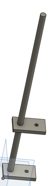
An alternative that comes to mind, but is less substantial is to make the setup below. It's two 10mm plates each 50mm x 90mm with a 16mm hole and a 10mm hole along the centre line, 16mm hole 20mm from one end and 10mm hole 25mm from the other end. The 10mm holes could bolt the plates to the beam flanges and then a length of 16mm threaded rod could be passed through the 16mm holes and bolted to the plates. That would create the third image when attached to the beam (nuts not shown). The plates could be stacked during drilling so the alignment of the two plates would be perfect.

-
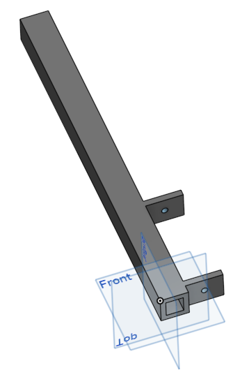
Thanks Gus Shouldn't be as the changes are associated with moving it parallel to the stringer direction so not narrowing the stair flight and the landing is plenty wide enough. It will be all timber (posts, spindles and handrail) 90mm x 90mm with height TBD (whatever gives the right handrail height etc) Nice and strong approach, that hadn't occurred to me. The posts are going to be centred 20mm in front of the beam so if it was 40mm SHS it could simply be welded across the front of the beam's flanges (see image below). Do you think 40mm SHS would be substantial enough I can't weld, but can bolt things together. Should I consider getting a length of SHS fabricated with two bits of plate attached to bolt to the beam flanges? The fabricator would probably struggle to get the spacing of those plates perfect, but as long as they were square to the SHS and less than the flange spacing I could pack it out. As an example, I have sketched up one (bottom two images) with 60mm long tabs of 10mm thick plate with a 10mm hole. I could drill the holes in the beam (or this part) slightly oversize to allow perfect plumb alignment. I am expecting a single M10 bolt both top and bottom be strong enough, does that sound right? Alternatively, if there is anything vaguely standard of a similar shape that could work I guess.
-
I wouldn't do that, but would have plasterboard in between any posts. Newel post is easier than the balustrade posts (same post shape as newel). It still leaves the challenge of how to anchor the posts since the centre is past the edge of the steel. Some options that occur to me include: Bolt a piece of flat bar to the top and bottom flanges of the beam and then drill holes in that through which I could pass a threaded bar which then goes up into the balustrade post(s) Timber infill in the beam which is bolted to the web of the beam. The post(s) then get screwed to that. Bolting the timber infill to the beam would require tapping the hole in the web as I don't have access to the other side of the beam to use a nut.
-
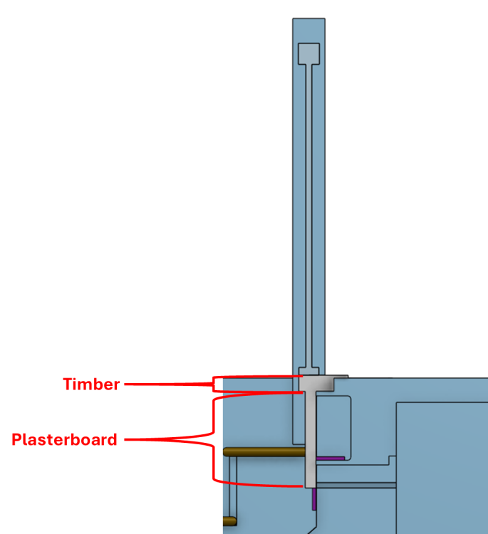
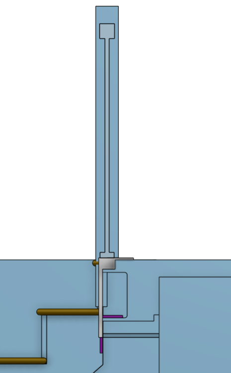
This is what that would look like in section
-
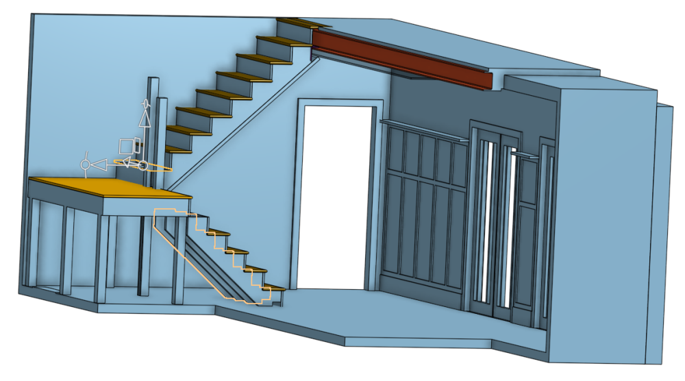
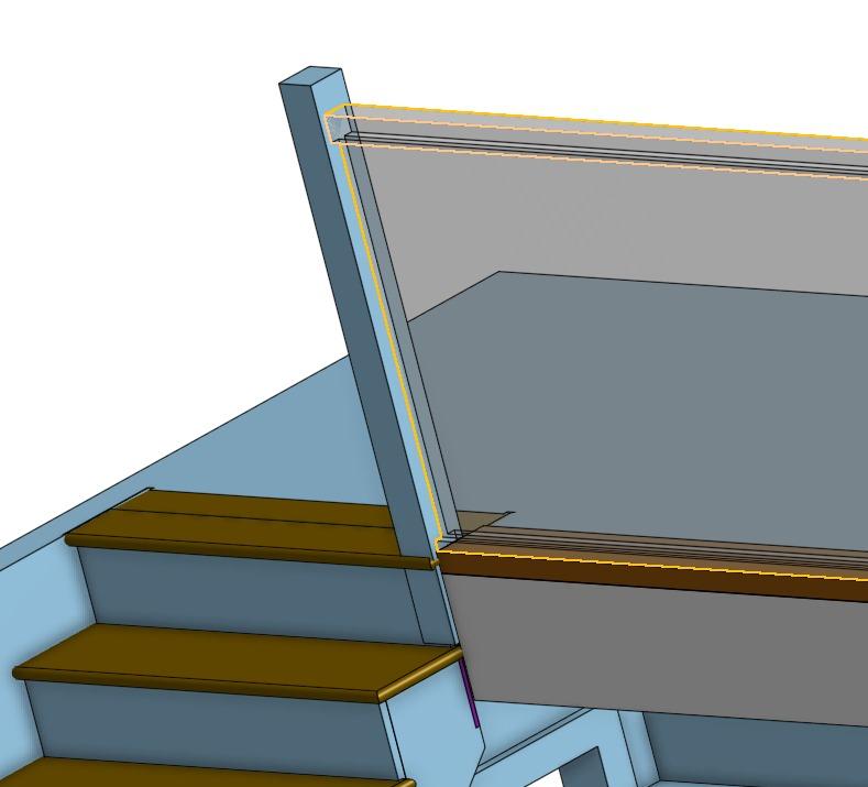
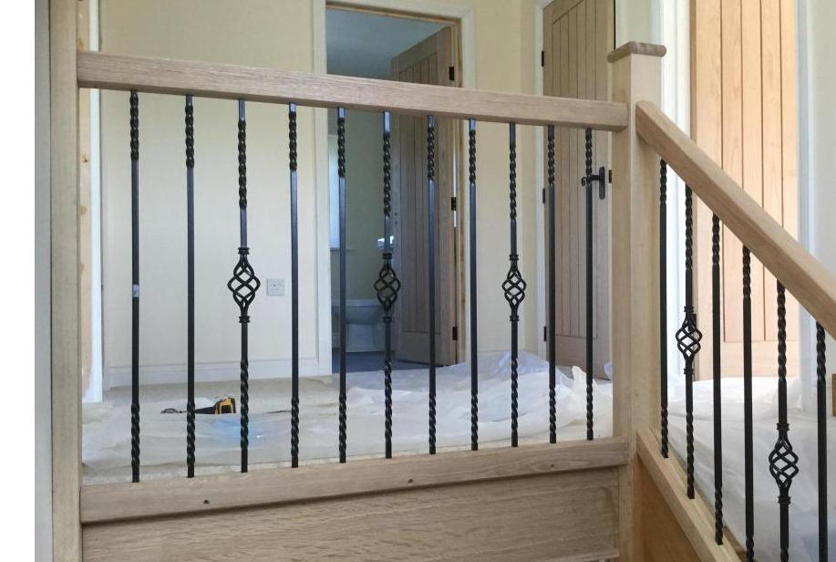
I'm positioning my lower newel posts to have one centre line aligned with the front of the riser and the other centre line aligned with the stringer's centre line. I can't so easily do that at the top since the riser is forward of the steel beam (red) that forms the edge of the landing. The plan is to clad the beam with plasterboard and have a piece of timber above that which then has the balustrade assembly on. That means the centre line of the newel post needs to align with the centre line of the balustrade which needs to be suitably far behind the edge of the timber above the plasterboard. As far as I can tell, that leaves 2 options: Push the newel post back relative to the riser, moving its centreline to above the beam Build out the full length of the beam (could overhang the timber slightly) to provide something for the balustrade to sit on. Option 1 is easier but looks a bit funny (see images below). The size of the move here is 38mm which comes from riser thickness (20mm) minus the plasterboard thickness (15mm) plus half the handrail width (60mm/2) and plus a small margin (5mm). I guess I could lose the 5mm. Option 2 could be made up of double cladding the beam to give and extra 15mm of plasterboard thickness, losing the extra 5mm and then overhanging the timber above the plasterboard by 18mm. @joe90 looks to have had timber extend out from the edge to create something like option 2 (image copied below) @Gus Potter you've had some good ideas on these stairs, what would you suggest? I'm slightly unclear how I would anchor the larger posts of the balustrade if I move it's centre line past the edge of the beam. I have been assuming using something like a zip bolt or threaded bar through the centre of these posts and through the flange of the steel. With the posts moved forward of the beam I would have more meat on them to straddle the front of the beam and perhaps bolt to the web?
-
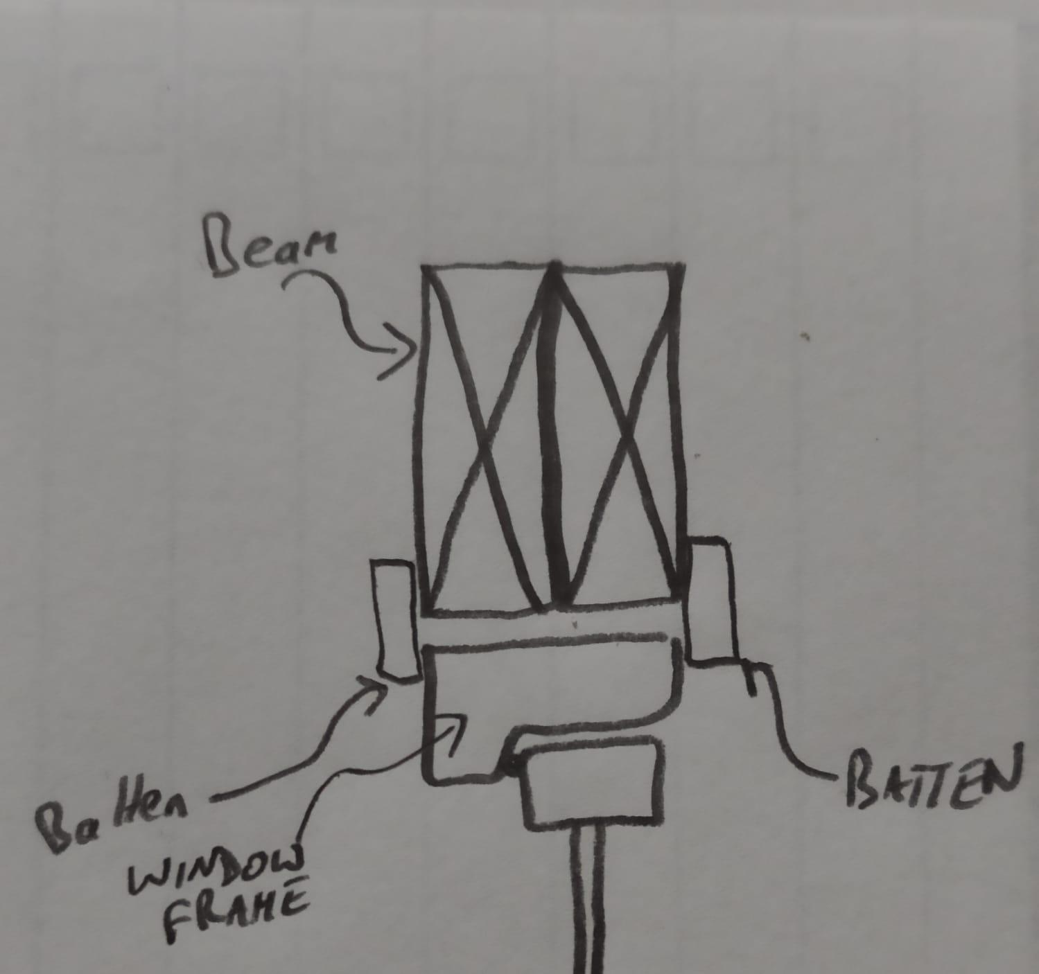
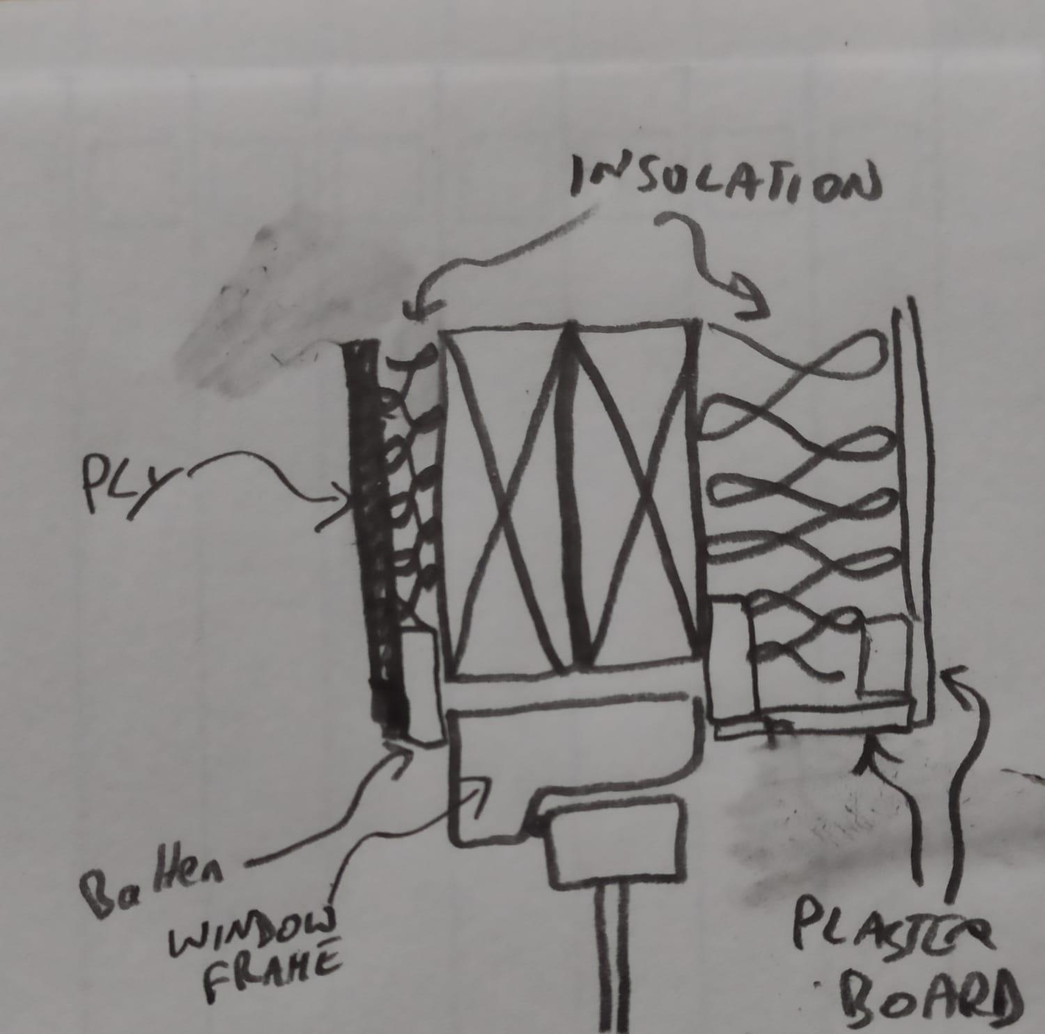
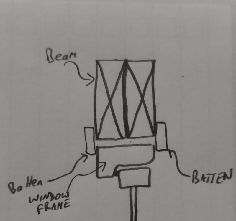
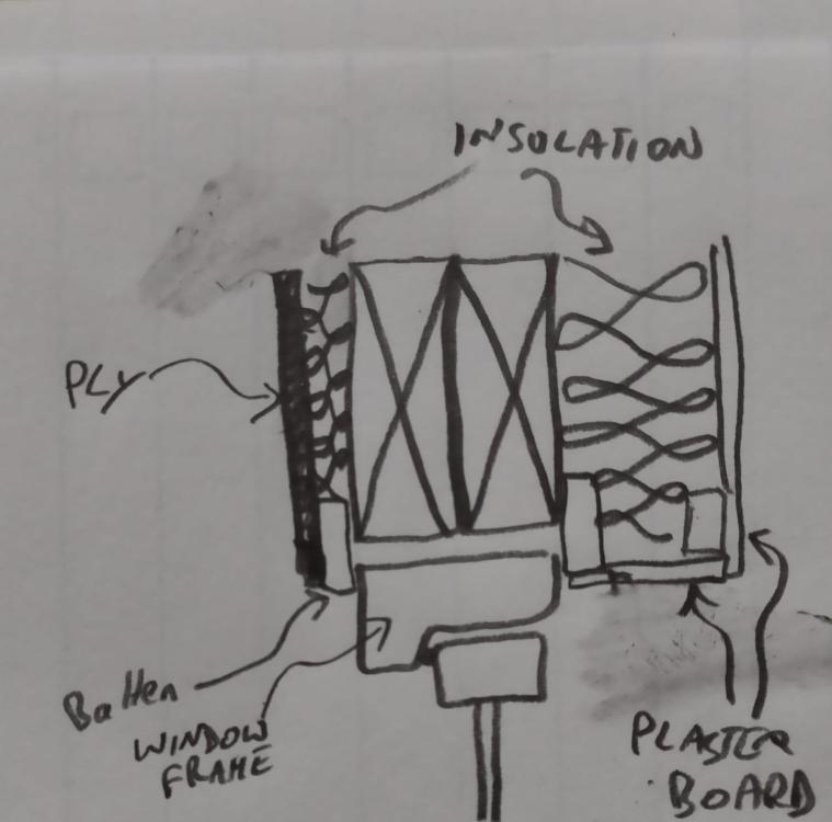
This is what I've come up with so far. I was already planning to have 60mm of wood fibre insulation on the inner surface of the beam and 20mm on the outer surface anyway. That needs to be covered with plasterboard inside so battens needed anyway. I could screw the batten to clamp the window frame horizontally but still allow vertical movement if needed. What do you think? What's normally done?
-
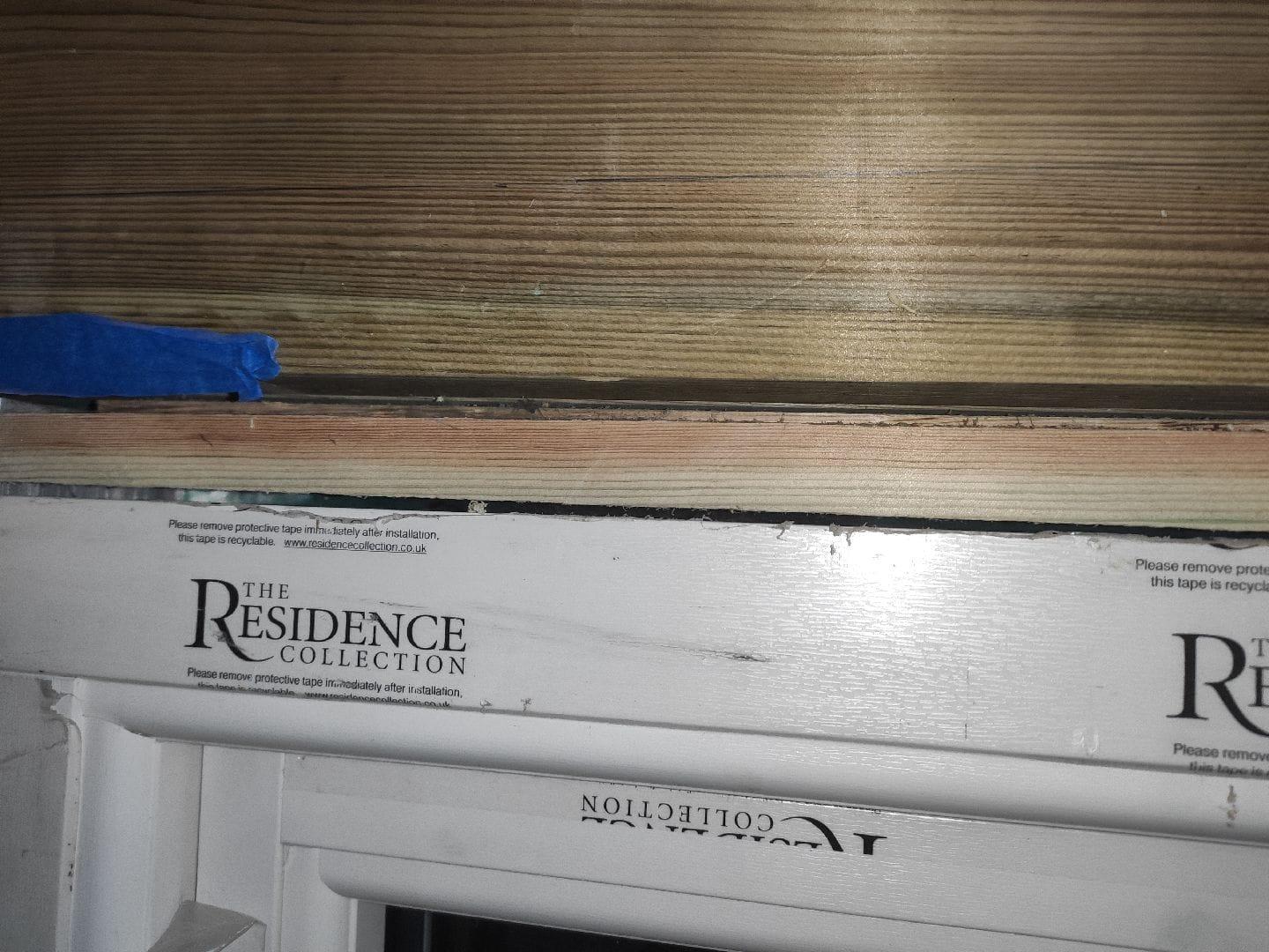
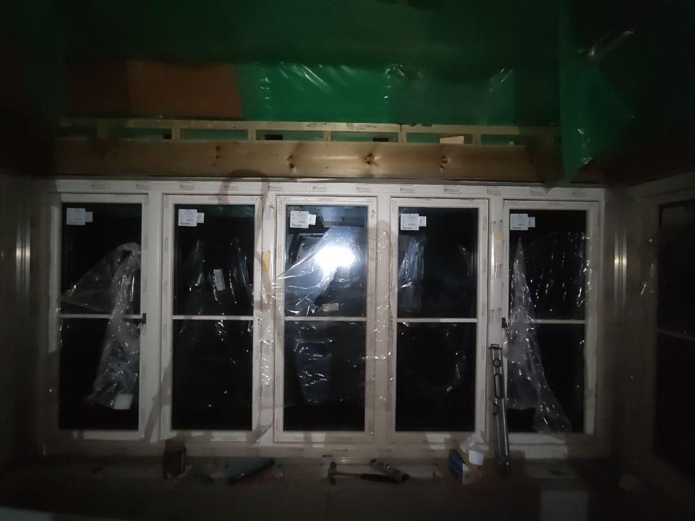
I have baypoles and jack's in the corners with a 2ply 195x45 beam over the centre 5 light window. It's a 3.2m span. I don't want the beam transfering any load to the window. How should I stop the window blowing in and out? I've left a 5mm gap between beam and window. If I put screws going up through the window frame into the beam it would transfer load. Note the beam has another now non-removable piece of wood underneath but that just to narrow the gap so not relevant.

-
200mm of insulation for the First Floor feels massively excessive to me.The concrete that insulation is sat on is in the heated envelope (unless over a garage) so is already warm. A well insulated house is going to have a low UFH flow temperature (e.g.35C) so thick insulation is a waste of money. Ground Floor sure, but not first floor. Insulation on first floor is only for responsiveness and zoning as far as I can guess.50mm would be plenty for that. Just seen your not the OP so presume you're talking about Ground Floor