
Radian
-
Posts
2586 -
Joined
-
Last visited
-
Days Won
15
Everything posted by Radian
-
I have these. Stainless Steel - bending is very difficult without putting what seems like too much force on the head of the slate below. Any tips?
-
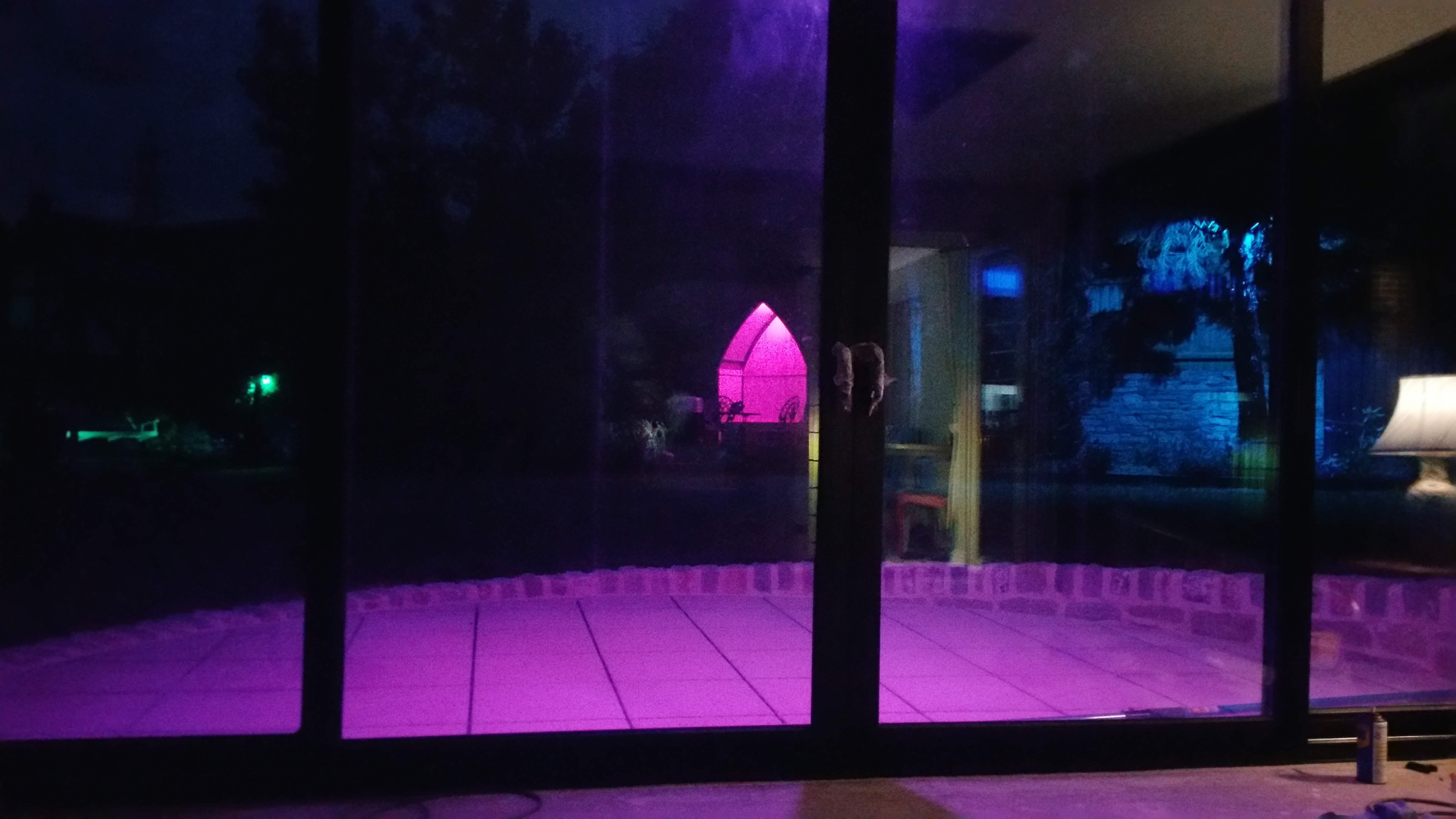
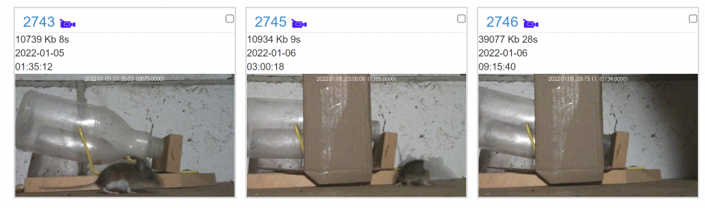
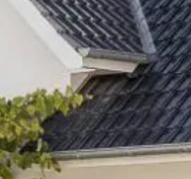
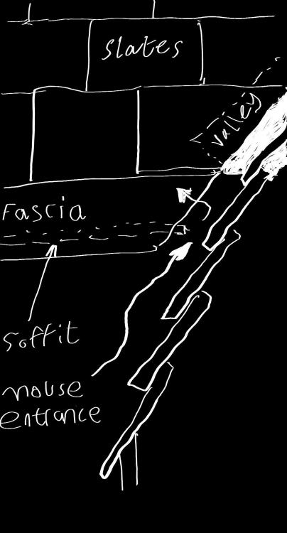
Every Winter we get at least one unwelcome house guest in the loft. This year is no exception.? The night before last, the little bu99er climbed on top of my DIY seesaw bottle trap locking it down with him on the outside. Look how he frantically wants to get inside to munch the peanut in there! How ironic. vi_2743_20220105_013504 (1)_Trim.mp4 So yesterday I made an arch out of a cardboard box to stop him climbing on top. At 3AM he got the bottle half way down by gingerly leaning into the opening, but it wasn't until later that he lost all will power and got completely inside. BINGO! Next stop, the back of Sainsbury's car park two miles away ? In the past we've released them closer to home (across a busy road) but on more than one occasion the same mouse has got back in the loft the following day so now we take them for a longer ride. Pure coincidence there's a nearby Owl sanctuary between us and the supermarket.? Ahem. At least we give 'em a sporting chance. But enough of that. I want some ideas how to stop? getting in. I think I know where as there's a very obvious entry point into the soffit box. This seems inevitable because it's where the eaves meets a perpendicular roof at a valley something like this: The cross section sketch shows the mouse entrance at the gap between the timber fascia and adjacent roof. The gap is necessary as water cascades down the GRP valley and down to the lower gutter. Looking at this junction from the inside of the loft I can see daylight here. The obvious solution is to spray foam the gap from inside the soffit box but this will bridge the fascia to the valley gutter and rot it out. The eaves have plastic vent trays all the way along the bottom of the first row of slates but stop at the gap no doubt for the same reason. Seems like a stupid design.
-
They didn't try it in my loft ? ? Seriously though, it can get very drafty up there with around 480,000 mm2 venting along the eaves perfectly aligned with the prevailing South Westerlies. I'm still thinking it would be worth it almost to get a maintainable surface. Cluster flies are an annual occurrence.
-
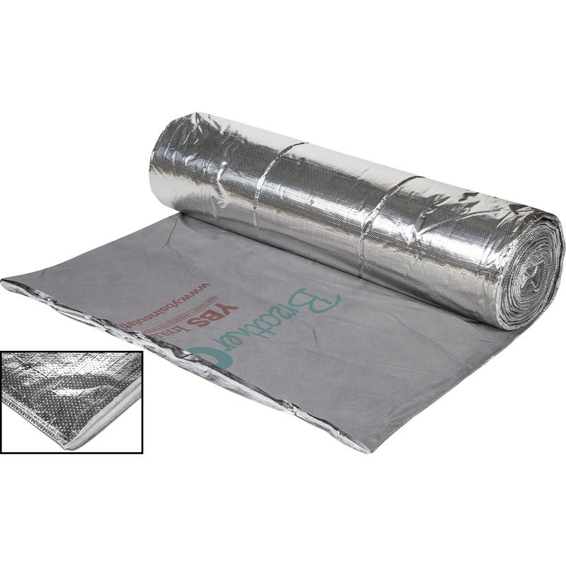
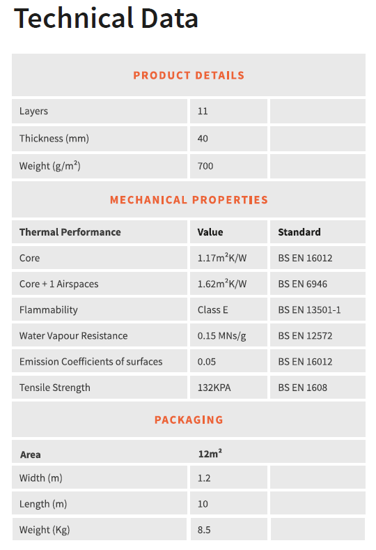
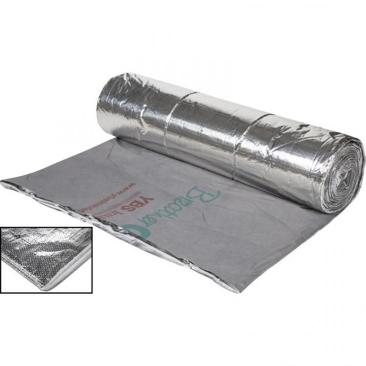
I've seen that mentioned as well "windwash" is the term I believe. Makes sense. I was wondering about using a breathable foil "space blanket" style sheet on top to prevent windwash and also to create a sensible surface that can be vacuumed - the current fiberglass has a layer of a couple of million dead flies and can't be hoovered. This YBS BreatherQuilt is described as "Low vapour resistant (good at allowing moisture to pass)" but does 0.15 MNs/g sound OK?

-
I'm adding extra insulation to an existing loft with only 200mm max. up there at the moment. I don't mind taking the old stuff up to put down a VCL but I wanted to check to see if it's really necessary. The only signs of condensation are on the vertical stack exiting the roof but I think I've nailed that. So the absence of a discrete VCL has proved OK for over 20 years in this house. However, if adding more insulation (aiming for 300mm everywhere) changes the vapour behaviour, I'm not sure what might happen. I don't know about new-builds but it never used to be a consideration in vented roof spaces. There again, they rarely had much in the way of insulation. Unvented spaces would certainly need additional vapour control - I get that. The only issue I can forsee is in the region I have boarded for access and storage. This is currently just T&G chipboard laid over the bottom truss chords which trap the insulation underneath. My plan is to attach 150mm x 50mm joists to the webbing, running parallel to the chords, to support the flooring 250mm further up to allow for 50mm airflow above the insulation. Alternatively I could bring it down to the sit on top of the insulation saving 50mm height so long as I have a vapour barrier under the insulation. But
-
I'm sorry if this proves to be a bit of an "old chestnut" but I've spent hours trying to find a definitive answer so I'm asking one more time... If putting in fresh mineral wool insultation between (and then a second layer crossing) over rafters in a ventilated (cold) loft space, what kind of, if any, Vapour Control Layer should I be putting under the insulation first? Some sources seem to suggest a complete vapour barrier (e.g. polythene) draped over the rafters and resting on the plasterboard to prevent inside moisture reaching the insulation. However I never like the idea of wrapping things in plastic: If extreme cold temperatures should ever bring the 'warm side' of the insulation down below the dew point (or if extreme loft temperature/humidity in the summer exceeds indoor conditions) then condensation may form in sensitive places that have insufficient drying-out capability. Other sources suggest using a Breather Membrane defined as a material having a limited degree of vapour resistance thus letting some moisture to pass in either direction. The latter sounds more sensible to me but just doing nothing sounds very similar given the finite permeability of gypsum etc. After all, in all the lofts I've seen, pink fluffy stuff just goes straight in! (not that that makes it the right thing to do though)
-
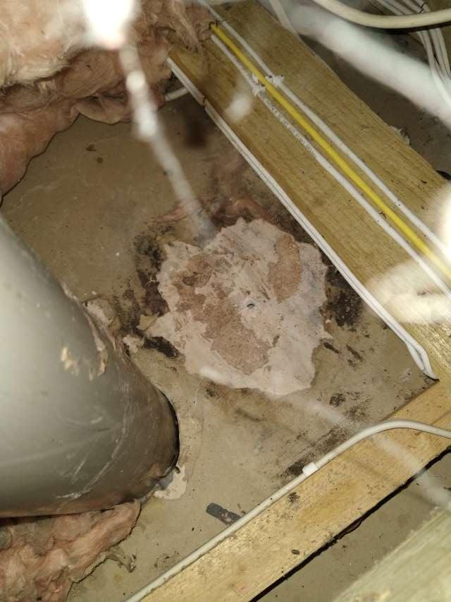
That's what I looked at first but the exit point is well sealed and shows absolutely no sign of water ingress. I think this is it... nice one! I kind of ruled it at at first because there is an identical stack on the opposite side of the loft and that was perfectly dry around the plasterboard. But the clue is in the direction the pool goes off in - notice the wet patch was on one side only, and there's an open vented CH header tank at the end of an imaginary line drawn between the stack, pool and nearby tank. And I was having a problem with warm system water circulating up the feed pipe that caused lots of condensation inside the tank. I'd forgotten all about this. I think I fixed that issue when I recently rebuilt most of the CH system but this has made me look more closely at how the stack comes up through the plasterboard ceiling. Below is a service box in the corner of a room that goes down two floors so plenty of warm air can come up. I will gun some foam around the gap for starters. But would it be necessary to lag the pipe where its exposed in the loft? The loft is ventilated but always that little bit warmer than outside so the pipe can reach the dew point first.
-
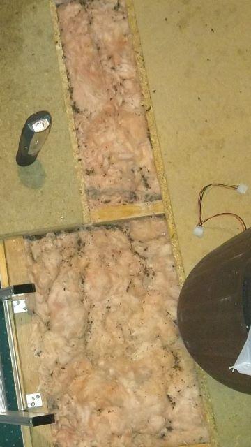
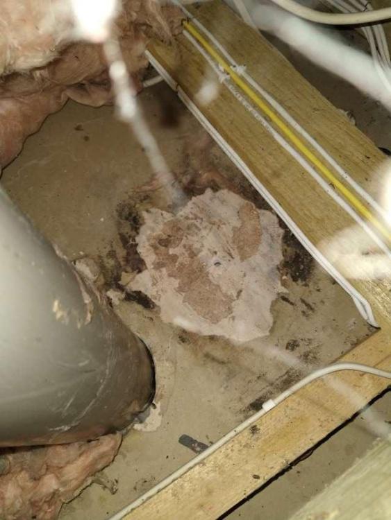
Up in the loft I pulled back some pink insulation around this sewer stack and found a wet patch: The card layer of the plasterboard was disintegrated and mouldy. The stain doesn't go much further than you can see in the photo so is not any kind of leak coming in from the edges of the region shown. It can only have come from above or possibly down the pipe. Neither of those options make sense to me as there are no signs of a leak anywhere above and the nearest plumbing is a meter away. The pipe is a little dirty and if the seal through the roof were to blame I'm sure it would show. But the stain does go right up to the pipe in one place. I'm baffled.
-

Insulating a Cathedral Roof - Mould and Condensation
Radian replied to LeRouret's topic in Heat Insulation
Did you ever bump into Richard Wright? -
I would look upon that as an opportunity to dump your excess power somehwere less piss-taking than the grid. The problem though is that you would only want the excess to go into the HW. That's what @ProDave is suggesting in point 3 above. A solar PV diverter like this one does it all for you. However, with some off-the shelf electronics from Ebay or Amazon and a bit of coding I would say it was probably something within the scope of a DIY'er for under £50
-
How the hell do you get the damn thing off!
Radian replied to canalsiderenovation's topic in Bathrooms, Ensuites & Wetrooms
Dunno nod, looks like the screws might be entirely inside the channel - glass pushed in after covering them up. Is it just friction fit in the soft plastic grips in the channel? If so, Silicone spray the heck out of it would be my suggestion before levering it out (carefully). WD40 is mostly silicone but also has oils. -
And if the empty 50mm cavity is filled with blown EPS having K-value (ƛ-value) of 0.034 W/(mK) we get R-value of 0.05/0.034 = 1.47 So replacing the Air gap in the above sum with EPS fill: Layer Resistance / m2 K W–1 Inside leaf 0.13 0.9 EPS fill 1.47 Outside leaf 0.9 0.04 Total R-value 3.44 So the resulting U-value drops from 0.46 W/m2K to 1/3.44 = 0.29 W/m2K which represents a 37% reduction in heat loss. Is it worth the expense if other issues are giving you a cold house? Note that EPS cavity fill does not provide any significant impediment to air circulation. According to the National Blown Bead Association (NBBA) one of its key selling points is that:
-
I have the same construction in my home so I'm curious about the U-value of this kind of wall. To calculate the U-value of an empty cavity wall constructed from thermalite blocks we first have to sum all the R-values of the material involved. Thermal conductivity (ƛ-value) from the thermalite aircrete turbo block web page is given as 0.11 R-value = thickness of the material/ ƛ-value e.g. 0.1/0.11 = 0.9 for 0.1m thick blocks. In addition to the blocks there are three layers of air adhering to the outermost and innermost layers, and the air in cavity. These are generally given as R-values of 0.13, 0.18 and 0.04 respectively for the inside, cavity and outside surfaces. Summing all R-values then: Layer Resistance / m2 K W–1 Inside leaf 0.13 0.9 Air gap 0.18 Outside leaf 0.9 0.04 Total R-value 2.15 U-value = 1/R-value = 1/2.15 = 0.46 W/m2K which is not exactly awful?
-
If fully wet plastered then at least you're not living inside a draughty plasterboard tent (dry lining). But having two walls of thermalite separated by an air gap would not immediately suggest a 'cold house'. Apart from heat loss through the walls do you have any other theories as to why its so cold? Is there loft insulation? Underfloor insulation?
-
'Fraid so WGL. On quite a steep pitch at 50°
-
True, but all the basic science is applicable to whatever construction work we're doing. I despair at the lack of basic understanding displayed by our typical building trades. To them the job is a 'goodun' if a big delivery of celotex turns up to site and finally disappears inside the building. Somewhere. And because nobody ever rings them up at 2AM complaining that air is pouring into their new building, they don't have the same appreciation for air-tightness that they have for water.
-
Shame there are only a handful of Feynman videos. Another good science communicator (who reminds me a lot of Feynman) is Canadian Building Science guy Joseph Lstiburek. I don't see much mention of him in these forums which is a bit of a surprise given how relevant his talks are to what we're all into here. To my mind, Joe sums it up when he relates how when its cold we don't swallow our sweaters but wear them on the outside (a few seconds in from this video)... https://www.youtube.com/embed/rkfAcWpOYAA?start=622
-
Wow, that takes some doing - what with photons not being the teensiest bit charged! Must have been detecting the scattering of electron positron pairs in a magnetic field then? Pretty obviously my dream Physics teacher would have been Richard Feynman who, incredibly, would be 104 now if he had not been stolen from us in 1988. I still feel very sad about that.
-
Thanks @SteamyTea I think you see what I did there - not reading the units carefully enough. My science teacher is very likely rolling in his grave. If not he has surely got himself into the Guinness Book of Records.
-
Oh Just realised. 0.042W per meter thickness per K! So yes, 1/0.15m x 0.042 thick = 0.28 Forget this ever happened.?
-
Sorry @A_L I'm having a senior moment here. When I take 1/R for the product listed I get 0.28W/(m2⋅K) which seems about right for a U-Value when I compare it with my double glazed windows that were rated at 1.6W/(m2⋅K) but the same list gives Thermal Conductivity as being 0.042W/mK which you appear to confirm as also being measured in m2 per Kelvin. What's confusing me is there's a big difference between 0.28 and 0.042 if they share the same units.
-
Whenever I look at EPS insulating panels I often see a list of parameters such as these: 150mm White Polystyrene Board (EPS) for External Wall Insulation (pack of 4) Thickness: 150mm Width: 500mm Length: 1000mm Pack coverage: 2m2 Density: 10kg/m3 Weight/m2: 1.5kg Weight: 3kg Thermal Conductivity: 0.042W/mK R-Value: 3.55m2K/W Compressive Strength: 75kPa Fire Rating (Reaction to Fire): E Here R-Value is given in m2K/W so if I want to convert to U-Value I would naturally take the reciprocal 1/3.55 = 0.28 Now that would be 0.28 W/(m2⋅K) right? But from their numbers "Thermal Conductivity: 0.042W/mK" what the heck is that? Is that meter.Kelvin or milliKelvin or what?
-
In case anyone handy with a soldering iron (and good life insurance) wants to replicate this, I offer my circuit diagram with all the usual caveats: On the left is a simulation of the bare solenoid connected to 240V RMS to estimate the power requirement. I used a multimeter with LCR ranges to characterise its inductance and DC resistance. Both these may change on your coil - especially if 120V is used. On the right is the simple half-wave rectifier with a current limiting resistor to maintain the same power in the coil. C1 has to be high-voltage e.g. 400V rated, D1 can be any 400V 1A diode (e.g. 1N4004) and R1 must be rated for something like 10W or more. It has to dissipate 4 or 5 Watts. Again, these values may need to be tailored to other switches but I would guess any 240V mixer switch that measured around 5000 Ohms on a multimeter would work OK with these values.

-
Me too. Thanks Roys! I'm told it came out quite well for a novice builder like me. Let's hope the overall design of the construction doesn't let it down - I think I thought of everything ?
-
Insulating a Cathedral Roof - Mould and Condensation
Radian replied to LeRouret's topic in Heat Insulation
I'm not in business myself and have no real feel for how much a trade would charge for this job. Here in the UK I would think the materials might amount to somewhere between £3K-£4K I'm guessing a couple of people might be able to do it in 3 or 4 days but I've never seen an actual example of your kind of tiles so don't have a feel for how long they would take to strip/replace. If it were mine I'd definitely have a go myself. Yes, well that's what I can't gauge from your description - how the load is distributed and onto what. The rigid insulation is relatively lightweight but here in the UK we would start at 150mm thick minimum and maybe go up to 250mm the further North we are which makes it somewhat heavier. I wonder what would be considered an appropriate U-value in your location? You might make enquiries. In your case I would also look into EPS (Expanded Polystyrene) as this might be the most lightweight option available to you. Depending on rafter pitch, the decking might be as light as 9mm ply and might be possible to be kept as a single layer under the EPS if, as I previously suggested, you mount the triangular battens directly on top. In this case you can work off of boards to spread your weight on the battens. The shallow pitch of your roof, the low height above ground and the lightweight nature of materials involved would definitely tempt me to DIY this and save several £K and get it done right.