TerryE
-
Posts
3806 -
Joined
-
Last visited
-
Days Won
30
Everything posted by TerryE
-
Jeremy, I use Screwfix a lot for many reasons: It's cheap compared to classic Builders Merchants (BMs) such as Travis Perkins. I live between a couple of branches within 15mins drive and service is quick, and their opening hours are excellent. I can buy online and know that the items will have been picked and waiting by the time that I get there. IMO, they very rarely score below 5/5 for the quality and functionality at that price-point. My only caveat is that for some things they've slowly been jacking up their margins over last few years for some lines. For example in plumbing. their bulk 10×90° elbows are competitive but some of the other slow turnover items are maybe 30% more expensive than Internet plumbing specialist such as the one that Peter mentioned -- if you can afford to wait the extra 2-3 days for delivery.
-
I am just going through the list of bits and pieces that I need. Whilst for the common stuff like end-feed Ts and Elbows it makes sense and is just easier to buy in 10, there's some stuff lie the 3/4" BSP male to 22mm compression elbow that I need 4 off. Just 4, and I am unlikely to need more or less, so if I go to Plumb Centre, say, which does a Pegler branded one at £10.58 inc VAT. I can get generic ones online for about half this price (e.g. here on eBay at £5.50). Both are brass components. I really can't see what the problems are with going the one for half the price. Both are brass co1mponents; passive fittings, and as far as I concerned if the the connect the bits that I need connected and don't leak then what's the difference? Any thought as to why I might be wrong here, or is there agreement on this approach?
-
We've made the policy and design decision for no mains gas in our new build. This has four tiers of saving: No Gas connection fees and these are typically ~£3K No need for Gas certified subcontract labour No daily connection charge No gas appliance annual maintenance charge This is a saving of ~£4K up front for the first 2. The last two cost us over £400 p.a. in our existing house (we could buy nearly 7,000 kWh for the same at E7 low tariff). We have got a 2-ring gas hob in the new kitchen, but that's run off a propane bottle outside. No PV because the planners said no, but we've got a wind farm and 3 solar farms within a 5km radius of our village and we will be buying green tariff electricity, so you could say that we've out-sourced the PV
-
Addressing backflow risks in Wet/Bathroom design
TerryE replied to TerryE's topic in Bathrooms, Ensuites & Wetrooms
A friend of mine was walking one of the coast-paths during the vacation when we were at uni. A big fizzzt and that was him done for. A surprising % of people who get hit by lightening survive. The main reason for death is that their heart stops or goes into fibrillation. If there's no-one on hand to perform CPR, then that's them gone. But we'd better stop this diversion otherwise Nick will tell us off -
Addressing backflow risks in Wet/Bathroom design
TerryE replied to TerryE's topic in Bathrooms, Ensuites & Wetrooms
I think that you mean that your house has been hit by lightening and you yourself not once and not fatally -- unless you are the forum ghost -
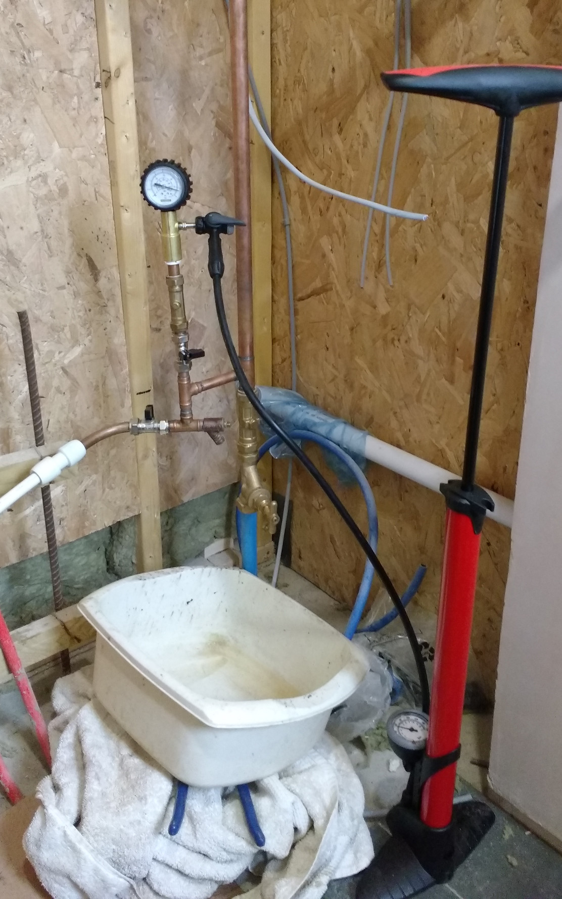
OK, One of the benefits of a manifold system is that we can do all of the pressure testing centrally. So is the T&J setup as per various feedback from Nick et al. I don't use the mains supply at the moment for anything other than testing. So coming from the mains I have: MDPE - Cu 25/22 stopcock : 22 Cu Double check valve : 22/15/22 T to (2) and finally a length of 22mm with an elbow and draincock at the top to act as a sort of air catcher / mini expansion Short 15 to 15/15/15 up to (3) and down to (4) 15 isolation valve, 15 double check valve and a Monument Dry Pressure Test Kit (£30) pumped by a Halfords Metal Trackside Pump (£18) 15 T to draincock and (5) 15 isolation valve and tail with Hep2O straight to hep2o flying lead which connects to whatever pipe or assembly that I wish to test. Most of these bits were old spares apart from the two price listed items so the setup was cheap and easy to make. The main disadvantage is that this Munson gauge only measures to 4 bar. But the set-up works well and the trackside pump is good for flushing out the test water so you don't leave drippy pipes after testing. Thanks guys

-
@Barney12 I am more than happy to go through all this, but it doesn't really belong in a topic about Alu cill depths. It's really about all the issues to do with adding a stone / blockwork skin to an MBC-style frame. I'll do a blog post over the weekend. Did you check your private mail?
-
Addressing backflow risks in Wet/Bathroom design
TerryE replied to TerryE's topic in Bathrooms, Ensuites & Wetrooms
IMHO. Can be both, but it's just that drop the H after someone got really arsey with me. Doesn't pee feels colder than the bath water? This is true for most actions that you do if they beach some regulation. However poluting the public water supply is a fairly sure one. IMO, if I had double check valves on the appliance and on the supply line then the risk of getting killed by lightning is far greater. -
Dual Hobs in Worktop, design vs structural engineering
TerryE replied to TerryE's topic in Kitchen Units & Worktops
Yup, ours is similar. Why the hell he designers don't put the touch controls at the bottom of the panel escapes me. -
Dual Hobs in Worktop, design vs structural engineering
TerryE replied to TerryE's topic in Kitchen Units & Worktops
Oops sounds like you need a stool or a stick with a rubber hand on the end in your kitchen -
@Barney12, no, MBC weren't proactive here. It was an issue that I picked up on eBuild chit-chat before we spec'ed the frame so we added 12mm on all sides to our frame window openings to give us room to insert the "shims", that is the framing. I've you haven't done this and the window openings are already agreed, then there is an alternative approach that either @ProDave or @Stones described (sorry, can't remember which; it was nearly 2 years ago) and this was to use something like the 38×44 tanalised construction timber to make up box frames which you screw to the outside of the frame openings once the frame is erected (depending on your detailing, then you might need to have an inverted U instead of a box) -- then you mount your frames in this. Most high-spec window frame profiles are 80mm+, so positioning them like this is fine. We got this right more by luck than by judgement. It's a pity that MBC (and other framing companies) don't go through this as part of their design check list. If you want to talk it through then PM me your voice details and we can do. That's if one of the other guy doesn't get there first.
-
Addressing backflow risks in Wet/Bathroom design
TerryE replied to TerryE's topic in Bathrooms, Ensuites & Wetrooms
Two comments: Repeating what some once said to me: "when have you ever been f**king humble in expressing your opinions?"; stick to IMO That's what I do. IMO, this debate isn't about real risks, it's about passing the inspection. -
Barney we have a similar profile except that our outer skin is stone ~125mm thick. What we did was to mount our windows in a narrow mounting frame (marine ply is typically used) so that the face of the windows sit some 45mm in front of the frame and largely close the cavity. This overhang is insulated by the cavity closers that surround each window. This makes finishing off the windows in term of weatherproofing, cills, etc a lot easier. If you look at the thermals is makes bugger all difference to heat losses and the slightly increased psi effect is still far above the thresholds where condensation might become a problem.
-
Addressing backflow risks in Wet/Bathroom design
TerryE replied to TerryE's topic in Bathrooms, Ensuites & Wetrooms
If you read that brief that I linked to FC1-5 is about protecting the public supply, and not necessarily about protecting the household. The difference between FC3 and FC5 as I read it is that for FC5, mandates a suitable air gap; a double check value (or even 2 in series) isn't good enough. In older non-pressurised systems this could be achieved by feeding the shower from indirect H/W and C/W primed from a cistern, with the cistern filled from a ball-valve -- and thus creating the airgap between the shower tap supply and the public supply. (This would not protect other indirect-fed basins fed fro the same indirect supply in the scenario that Nick discussed, BTW.) The problem is that this type of gap doesn't exist with modern pressured systems, so the Building Inspector should therefore fail any configuration which breeches this guideline. The easiest way to avoid any issues during inspection would be to comply with it by fixing short hoses or adding "permanent" restraining rings on the hose lines so that any shower hose passes the "can't reach the pan" test. Whether you remove it or not after the inspection is your affair. You might feel that a decent double check valve in the shower feeds should be perfectly adequate, but if you do and this does fail then you would be legally liable for the contamination that occurs. -
That's why it is in the Boffin's sub-forum but when JSH, ST and anyone else with informed views and I have reached a broad agreement to all the geeky shit and agree on conclusions, then I'll do a blog post summarising the "how to" in a blog post or mainstream topic.
-
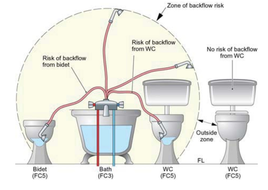
This issue is one that you could come a cropper with your BInsp if you aren't careful. Here is a good paper written for WRAS which explains the issue and figure 2 is the nub of this issue You have to prevent the risk of backflow at two separate risk levels: (FC3) For basins and baths you can use double check valves, a self cancelling diverter (one of those button ones where the button pops if the flow stops), or a guaranteed airgap (FC5) For anything where liquids containing shit or its micro-orgamisms can pool, and in particular for toilets and bidets, these must be air-gapped with no exceptions. An airgap means just that. In old indirect systems that were fed from a ballcock, using the indirect hot and cold on the shower feeds would meet this requirement but on pressured systems there is no such airgap internal to the pipework. What this means is that the hose nozzle must be physically prevented from being able to be dropped into an adjacent loo or bidet. This means that you have to ensure that the hose is either too short for the nozzle to reach or that there is some restriction that effectively limits the hose length to achieve the same, such as a fixed shower screen between the pair or a permanent restraining clip around the hose. If the geometry / layout of your room means that this is a risk then using a very short hose or a permanent restraining clip to prevent this is the minimum that you should anticipate needing to get sign-off. How permanent this constraint is after the sign-off is up to you and your conscience, but this is a real risk to the water supply.
-
Peter, what gets me is that I often can't find what I am looking for or I am spoilt for choice, and both do my head in. So take two examples: The draincocks. I know when and where to use them. I've end-fed soldered them in the past so technique isn't the issue. However I was searching Screwfx to buy a few and could find them: drain, too many hits; drain valve, too few and the wrong ones. I had to know to call the bloody thing a draincock. Durrrhh! PRV. Again we are spoilt for choice so it would be good to know which actual model people have used. Putting the bits together once you've bought everything is the easy bit, IMO.
-
Effectively no, mains quality what is a pretty poor conductor: good enough to electrocute you but not good enough to use for earth continuity. On this main thread of DIY plumbing, this is a mix of design knowledge, techniques and skills and quality. As Jeremy commented the building industry in the UK is dogged by poor quality. I've worked in IT all my life and for three years my title was IT Operations Director for Rolls-Royce (the aero-engine one not the car one). Now that is a company that has quality as part of its DNA and culture, and IMO pretty much at the opposite extreme of current practice in the building industry. In IT whether application development or IT services where I worked for the last 10 years of my career, there is still a good quality culture. Processes and procedures were documented; testing and review were build in; essentially everyone was subject to independent scrutiny and accountable for there outputs. Lessons learnt where aggregated up and fed back into improving the processes. This was just part of the culture, and on the IT services side of my company I was at the top of that review and assessment pyramid in Europe. It wasn't perfect but it was a different world away from what we see in the building industry today where individual tradesmen work largely unchecked and in isolation. Now the average self builder will definitely not do as good a job as the top tradesmen, but IMO a best Q is to ask: with a small amount of advice and support (and sometimes testing / certification), will he or she do better than the average tradesman working to a rate that they can afford? And I think that the answer is "yes, definitely" for most knowledgeable self builders.
-
As far as I can see you need the SAP rating for Building Approval and some people need a A rating for some BSoc funding approvals, but after that it's either an ego thing, or a sales gimmick. We're not planning to sell our new house, so I don't really care about the SAP rating, just the true operating parameters such as performance, operating and maintenance costs. Jan's residual concern is about the summer peak and whether we will need the ASHP to provide active cooling.
-
@jack, can you use for mod privileges to move this last post out of this thread onto the parallel Boffin's thread on the UHF / slab design. What I poked you for here was a description of your mains riser chain, that is your stopcock / double check valve / filter / PRV and any isolation or drain valves; how you've configured this. [@TerryE, I've moved the post to your other thread and deleted it from this one. I'm leaving your post here for reference]
-
We might have the same problem but in our case mitigated the worst of the symptoms by an unintended consequence of an earlier design decision: we originally had 4×90m loops but I asked MBC to remove the areas under the units and breakfast bar from the cover. At this point it was just easier to drop to 3×100m so we also dropped the utility room -- except the feeder runs into the manifold which all run into it. But I was also thinking of doing a plate model were I approximate the slab by say 500×500 tiles with a plate heater at 40mm below the surface and (1) treat the UFH circulation as a very high horizontal cp on plates where the UFH is routed and (ii) include the deeper ring beam areas, again with an increased cp to reflect the overall effect of the rebar. But this is a lower priority at the mo. Jeremy, if you want to remove the buffer tank then you need to trim your other control mechanisms: (i) I recall that @jack runs without a buffer and sets his ASHP output temperature down to around 25°C at which point it is outputing around 2kW (this will depend on the low rate), and (i) you may need to open the UFH TMV mixer threshold slightly, because it's the limits on the Δt that in turn limits total amount of heat that you can dump into the slab in one go. At the moment I am planning on a single dump during E7 low tariff period because I am using an inline heater, however if I was using an ASHP then it might be better to use smaller heat slabs 2 or 3 times a day, say equating to the ASHP running for 30-60mins. More modelling
-
What would be really useful for people like @joe90, @jamiehamy and me would be to some of those that have been through this such as @jack, @Calvinmiddle, @JSHarris, @PeterW, @PeterStarck just list off their feed stack in terms of components used that is from the MDPE coming in to the split of feeds to DHW and DCW, plus maybe any comments on any retrospective +/-s. And not forgetting the pros here like @Nickfromwales
-
As I said in another post if I compare our 20-30 year-old plumbing in our current house and the HEP2O manifold system in our new house, they are truly a generation apart in terms of technology. It's not just the materials, but the skills needed to do the latter are fundamentally different to the former. The old system was unpressurised, all in copper and loop-based so lots of solder joints in inaccessible places. The only active components were manually operated taps. In general this was very energy wasteful. The new system is plastic / push fit radial so no joints within the building fabric; the system runs at a limited mains pressure and there are sensitive active components. A large amount of thought and planning has gone into achieving the overall energy efficiency. The old system was a trade and the new a technology that requires a professional approach and a lot of the old trade skills are simply redundant. Yet I suspect a large number of plumbers (probably a significant majority, IMO) have yet to make this switch, so the consumer or self-builder might be very constrained by the skill set of his chosen plumber. A friend of mine doing his own new-build is in exactly this situation: "old-school" plumber = old-school installation = expensive and energy inefficient. In our case we can easily supply most of the skills and labour needed. And in a lot of area such as layout planning, scheduling with other trades, component procurement we're probably a lot more skilled than the average plumber. What we really need is a few days for high-grade professional services: to do the component selection for the active components and to review our design, and then at the back end to commission and test the completed system. I'd happily pay double the going plumbers day-rate to get this sort of quality service, but it would only be for a few days so it would still make economic sense for us. But for the true professional plumber, this is a very niche market.
-
Replies to Qs The GNU gfortran compile is part of the GNU gcc bundle so adding it takes seconds on a Linux (or Cygwin if you run Windows) if you haven't already got it installed. It is Fortran90 and I use the F90 features, so it is a little different from the old F77 that we both used last time in anger. I initially wrote the early versions in C but the C language just gets in the way of reading the code and understanding what is going on. So I moved it over to Fortran as this sort of application fits it so well. So I prefer this. As to the GUI approach, all of the parameters are just that, a block of Fortran parameter declarations (one of the F90 additions and which the compiler treats as compile-time including things like real,parameter::pi = 2*acos(0.0) which is nice). If I want to change anything, just tweak the parameter block, save and recompile; it only takes a couple of seconds. So no fancy input parsing; I leave this to the compiler. As to the output I simply dump CSV data to stdout, and post process this with (LibreOffice) Calc. for example my main output code is: write(fmt2,'(A,I4,A,I4,A)') '(I5,1H,,I5,',2*nRings+2,'(1H,,F8.4),1H,,F12.4)' do i=1, nSections write(unit=*,fmt=fmt2)iter,i,Twater(i),(T(i,j),j=1,nRings),(W(i,j),j=1,nRings),Wair,Q(i) end do (The first line is standard hack because you still can't provide a variable count in a format repeat group.) Sometimes I might use a shell filter such as grep -P '^\s*\d*,\s*50,' /tmp/a.lst > /tmp/a1.lst as a post process. (This picks out all lines with the second field = 50, that is the midpoint in the 100m loop), to keep the Calc file smaller. If such a filter is useful, then it's trivial to add it to the code as an extra line or two of logic. Nick I'll cover this in my extended discussion below. Basis of the model (This section can be skipped by normal mortals, but this in the Boffins sub-forum after all.) My passive slab has ~73m² of concrete 0.1m thick – that is roughly 17½ tonne of concrete in total across the footprint of the house, but the slab also contains another 10 tonne of perimeter beams, cross bracing and steel beneath this which all adds to its overall thermal capacity. Some 55 m² of this is covered by Under Floor Heating (UFH) pipe placed roughly 50 mm below the slab surface in 3 loops, each just under 100m in length and laid in the standard “double back” spirals used in most UFH designs. There is 300mm EPS below and to the sides of the bulk of the slab, so the main (radiant) losses are into the living space above it. Accurately modelling this type of design is practically impossible because of the uncertainties introduced by the steelwork within the slab, and of huge computational cost of executing a time-varying 3D spacial model. So what I wanted to do here was to focus on the time dynamic and heat propagation effects around the pipe run themselves, by modelling an approximation which is more easily simulated but which will have the same macro characteristics of the heat flow through a real concrete slab. So what I am going to focus on in this model is an approximation which is a 100m long homogeneous tube of concrete some 150mm in diameter with a hole running through the middle some 14mm in diameter. Water is circulating through the centre hole at 1 m/s and is heated by a 1kW heater at one end. The surface of the concrete tube is radiating heat into a black body at 20°C at 3.5W/Km². The initial temperature of the concrete is 20°C. My reason for choosing this radially symmetric geometry is a pragmatic one: that this type is it is radially symmetric and therefore computationally solvable with a 2-D approximation, (and its steady state can by analysed analytically). The 3 × 100m pipe runs have a total volume of 5.3m³ which is pretty much the same as the piece of the slab covered by UFH (albeit roughly half of the total mass). The total surface area of the 3 tubes is 141m², which is roughly double the radiating area of the slab, so halving the normal approximation of 7W/Km² will give a similar net heating effect as the actual slab. The 1kW × 3 tube arrangement is directly comparable to the 3kW inline heater that I plan to use initially. So overall this model is good enough to explore some of the issues and performance characteristics that I want to quantify. I approximate the concrete mediums by a set of concentric rings at a uniform mesh interval. As previously mentioned, since the radial temperature gradient is nearly 3 orders greater than the axial gradient in practice I can practically ignore the cell heat flows though the concrete and assume that the only axial heat flow as as a result of the circulating water. Removing these terms also allows me to increase the ∆l (intervals along the pipe) whilst keeping the evaluation stable. By assuming that each material layer is a fixed multiple a fixed thickness ∆xi and by using a fixed time step ∆t, the solution can be approximated on a fixed (∆x, ∆l) mesh using a n∆l × 1-D implementation of a formulation of a simple delta approximation to the 1-D heat equation. This formulation uses 2 material properties that are specific to each material in the wall: VHC the (per) Volume Heat Capacity, which is just a product of the density ρ and the heat capacity cp K the thermal conductivity It also is expressed in terms of the heat flow, W, at each layer boundary and of the temperature at the centre of each layer, so for the jth section of concrete pipe, Tij is taken at midpoint between boundaries i and i+1 and conversely Wij is calculated on the layer boundaries between temperatures Ti-1 j and Tij. Note that a positive W indicates a left→right heat flow (that is T is decreasing in the direction of increasing i). The basic equations internal to a given layer are straightforward and documented in the source code. I've left discussion of the heat equation itself to Wikipedia, etc. Analysis of the Results and What This Tells Me This modelling the slab as three pipes of concrete has some strengths and some serious limitations. The main advantage is that this gives us some understanding how the slab reacts to a prolonged heating period followed by the heat source removal. What it is missing is that this radial approximation will start to break down as the heat diffuses through the slab, and in particular in my slab where I have large internal and perimeter ring beams which add another 70% thermal capacity of the slab and I'll return to this point later. When the 1kW heat is applied it takes a few minutes for the return to start to lift in temp because the slab is cold and sucking all of the excess heat out but over the first 15mins or so it then settles down to a quasi steady state where the 1 kW generates a lift in circulating temp by some 1.6°C so there is a steady thermal gradient of roughly 0.016°/m along the pipe. The radial profiles then slowly rise and the whole temperate slowly increases to support pumping 1Kw/100 = 10W per metre into the concrete. The temperature profile of an individual 1m segment looks very much like the analytic solution to the radially symmetric 1-D heat equation because the second order terms are so small. (I've updated the first graph above to show the temperature profile of the water over time for the start, middle and end of the pipe, and which shows this.) The ambient air temperature plugs into the outer boundary condition. The external heat loss is represented by a radiance of 3.5W/Km² at whatever the external Δt is. This is a bit of botch because the real value is nearer 7 but only half the area is exposed, so this gives the right ballpark for the BC. As soon as the heat is removed, the slab rapidly transitions into a different mode. Since the radial profile is no longer being pumped from the centre, the 1/log(r) type profile starts to relax back to a more uniform profile as the heat start to spread more uniformly through the pipe cross-section. The circulating water now acts to redistribute the heat created by the 1.6° gradient pretty uniformly along the concrete "pipe" and another hour or so the difference along the pipe is minimal. It is really by this point, say 5 hrs, in that the radial approximation begins to lose its validity. The slab is acting far more as a uniform plate some 75mm thick, insulated below and radiating above. In my case the heat energy will also started to get "cached" in the beam underworks partly assisted by the rebar acting as heat pipes. So whilst the general shape of this curve will remain the same, I think that my real slab will be more sluggish in dumping heat so the curve will be flatter. My Conclusions You can use the slab as a buffer If you want to pump 3 kW into the slab then you need to accept that the circulating water temperature will rise of its own accord maybe 5-7°C more than ambient. Alternatively if you limit the Δt a few degrees than the rate at which you an pump heat into the slab will be limited accordingly. Measuring the flow return temperature is the easiest way to instrument the overall temperature of the slab (so llong as you ignore any heating periods and for maybe 3 hours after any heat input.
-
Dual Hobs in Worktop, design vs structural engineering
TerryE replied to TerryE's topic in Kitchen Units & Worktops
In a previous post you mentioned that you were hankering for a handle-less look. With a plain handled door style you could fairly easily swap out the door for a different colour in the same or visually similar style and transfer the handles to maintain the consistency. The disadvantage of a handle-less look is thaat the handle is sculptured into the door profile and is part of the door itself. Companies temp to redo their styles every 5 years or so, so there's no guarantee that you will be able to source doors with the same handle profile. Just a thought to factor into your design choices We are only a couple of hours down the M1 off J15 , so if you and Ian are heading down the M1 south, why not arrange to pop in and look at what we've done.