
Adam2
-
Posts
793 -
Joined
-
Last visited
-
Days Won
1
Everything posted by Adam2
-
 Thanks for the link, also listed I saw this one which looks to be easier to use as I think you can probably more easily put the clamp around the live or neutral vs having to always disconnect. BUT - are there options which allow a clamp around the 3 cores in a typical LNE supply that will provide accurate/reliable readings?
 -
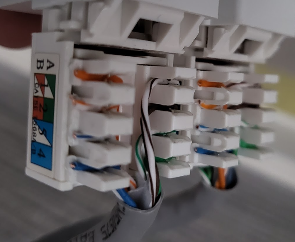
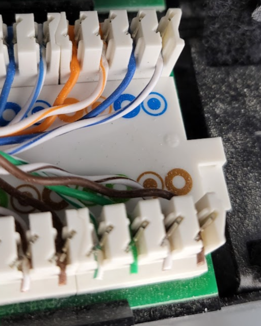
Ahh the fond memories of the ISO 7 layer model 🙂 Thanks for all the valuable info, always good to learn. I think the cable installer just had a brain fart and systematically crossed the oranges in the faceplates - he was being assisted by his old man so possible that there was some miscommunication. Even though seems to work I'll swap them to align with the labeling for piece of mind and at the same time check the + punch down again to make sure all is good - not too many anyway. May also go buy a more comprehensive tester - not long until Christmas!
-
Thanks @MJNewton will look at switch spec and do my test above to learn a bit more 😀
-
Ok which is what I originally expected. So that bega the question as to why my switch (unifi 24 port POE) reports a Gb connection when the wall plate looks to have bad wiring. Feels like some key info is missing. In morning will wire put a device on the end of a port with what looks like switched over orange cables and then on one that I've terminated as per the B layout image and see what the switch thinks about that. I wonder if it does some magic to determine incorrect wiring or something clever.
-
OK thanks - so more info 🙂 The tester I have is this one basic - just shows a LED for each pair 1/2, 3/6, 4/5, 7/8 - writing this makes me notice a typo in the original message which I'll update if poss. When I connect the following: 1 - Patch panel port with terminations as per images (supplier says is "B") 2 - Cable from patch panel into tester 3 - Other end of tester - cable running to wall plate - wall plate wired as per "B" image on the keystone module 4 - Cable at back of wall plate terminated into patch panel (1) Tester shows 2 green LEDs pairs and 2 LEDs not lit at all - I did an experiment to see what condition causes no LED vs red LED -seems red LED is a pair that is crossed and no LED means one of the wires in a pair is not connected. When patch cables are used on their own - so a single cable plugged into both ends of the tester - I get 4 green LEDs indicating all pairs working as expected From looking at patch panel looks like all wired the same.
-
Thanks yes have a cable tester which I used and had results above. Just cannot understand how the wall panel can be wired incorrectly as per the colour on the module yet do 1gb connection and cable tester reports 2 pairs with no signal maybe I'm using it wrong or something but it is simple just 2 cable connectors and some lights to show each pair...
-
I had a company come round to sort the patch panel and some wall connections etc. The panel is as per the images on the back of the 48 port panel (supplier says intended to be wired as T568B) I took one of my wall plates off as I wanted to see if they had wired up as T568A or B as I needed to do another wall plate myself. When I took an existing one off I noticed the orange cables were swapped - weird, almost T568B. So, I plugged a pre-made long patch lead into the wall outlet and used my patch cable test device to connect this into the patch panel - it shows 3 pairs as not good and 1 pair as good. so weird - thought it would be 1 pair bad. So - swapped the oranges around and now I use my tester and I have 2 pairs good and 2 not showing any connection WTF??? Looked at another faceplate - wired the same with oranges seemingly crossed. On one of these I have a laser printer connected and the switch (Unifi) reports this as being a fully operational 1Gb connection - which I guess means 4 pairs need to be working correctly. Clearly I'm very confused - any pointers appreciated to calm my confusion 🙂 Else will call installer in morning to see what he thinks.

-
OK well, I'm glad I couldn't meet your expectations on this occasion 🙂 We've had our fair share of dramas along the way. Will request that the replacement is heat soaked and will get the supplier to install as well as my tilers are understandably not excited by the prospect of doing this again! Next time we'll design out any ideas of a 2m x 2m shower screen
-
Today we'll discuss costs for replacement 😖
-
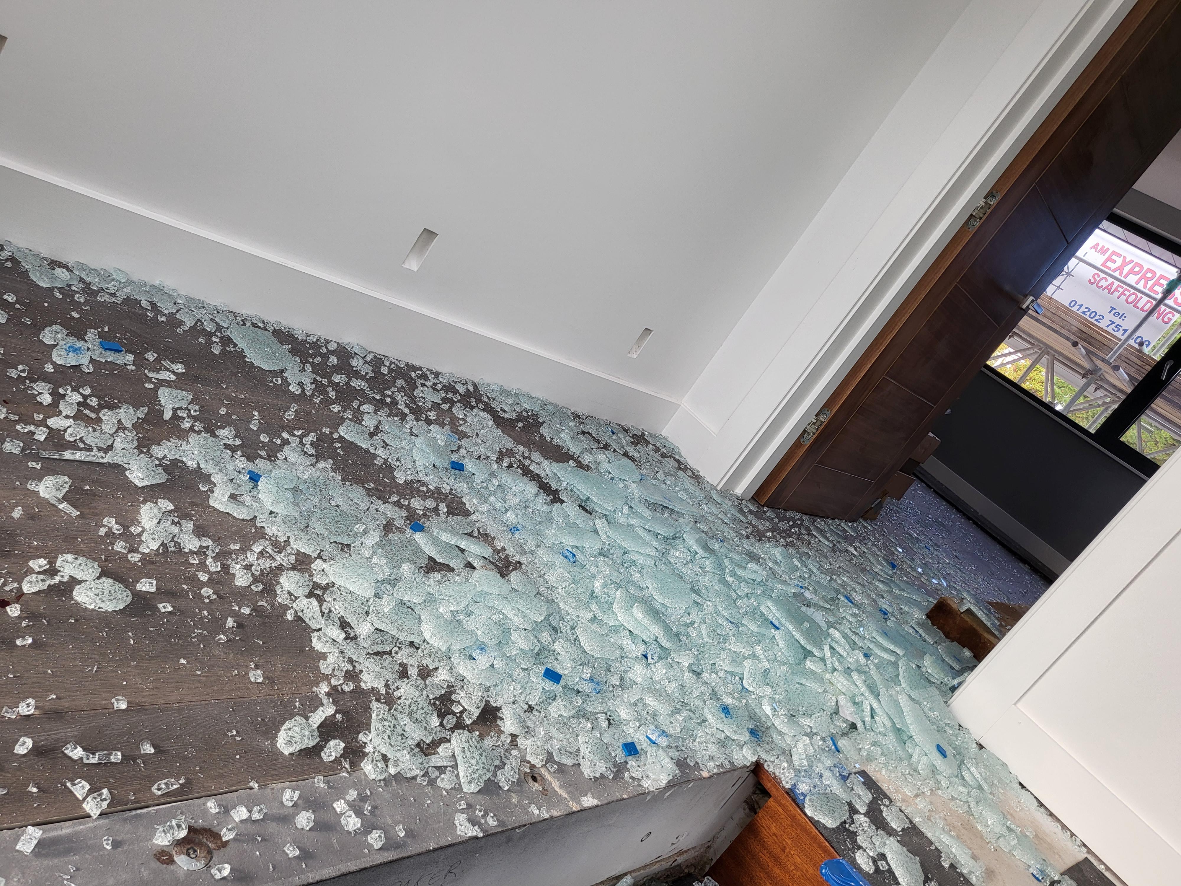
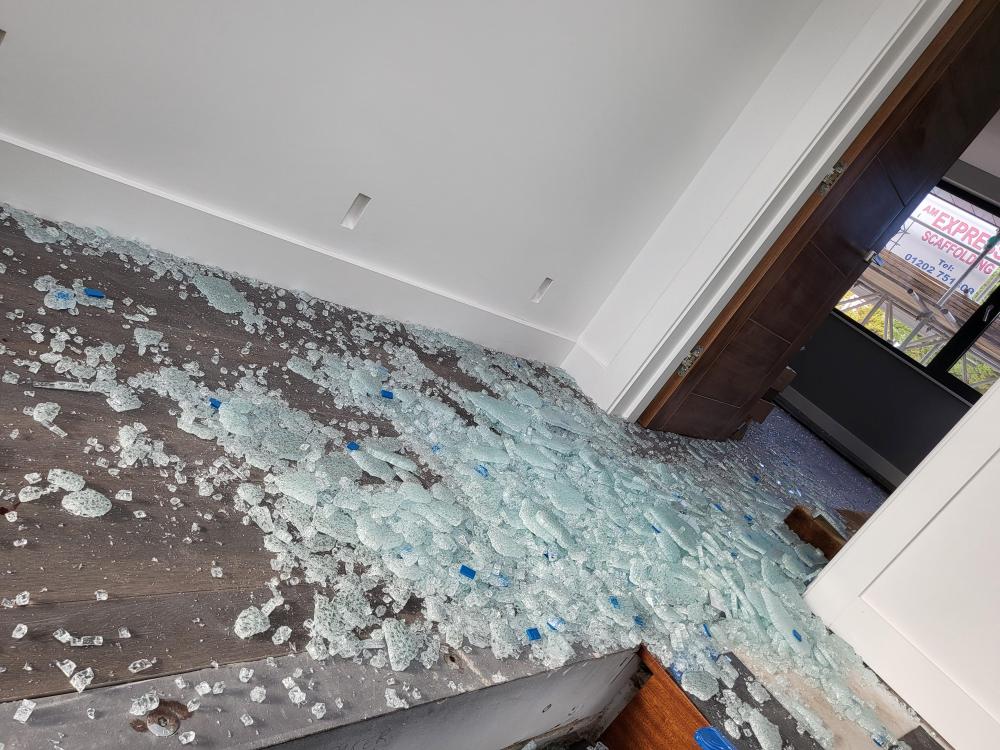
Anyone else had a huge piece of glass explode on them? Today had a 2mx2m x10mm toughened piece shatter while 4 of us were carrying it. Only minor cuts but could have been a lot worse. I think all in a state of shock after. Made a right mess of the floor. How could this happen?
-
Very interesting, will see how this goes and if happens again look at cable size
-
So, I used the app to change to heating only (as it was stuck on hot water cylinder priority I guess) then turned off for 15 mins. Turned on and all OK on heating and no more alarm ! 🙂 Left that for a while to get the buffer up to temp then put back to heating + hot water and after a short time it switched to hot water and seems OK. So emergency over 🙂 Will try and find the cause but if happens again I guess try the same but this is the first occurrence since installed in March - though does probably coincide with the first cooler night (8 degrees). If I find a possible cause will share on here for others
-
So, as soon as I comment that things are working well with our Cool Energy iVT-18 ASHP, I notice the control panel is showing an alarm code AL114. Not a very helpful message to describe it: "Power+ alarm:Power+ offline". I've tried the "IT solution" turn off leave a few mins and turn on - still the same. If anyone has seen this before or has suggestions please let me know as would be nice to try a few things before contacting them at Cool Energy as they seem not to be there at the mo.
-
Another 'Cool Energy' heatpumps thread
Adam2 replied to HughF's topic in Air Source Heat Pumps (ASHP)
@HughFis there not some new scheme where you get 5K off an ASHP if replacing a boiler? Since ours was signed off on the last days of the previous giveaway I didn't follow closely enough what the current incentives are. My CE ASHP pump has been up and running a few months now and all good really, just sits thee doing its job - may well look more at opimisations at some point but have painting to do seeing as decorators don't know what "good" looks like 🙂 -
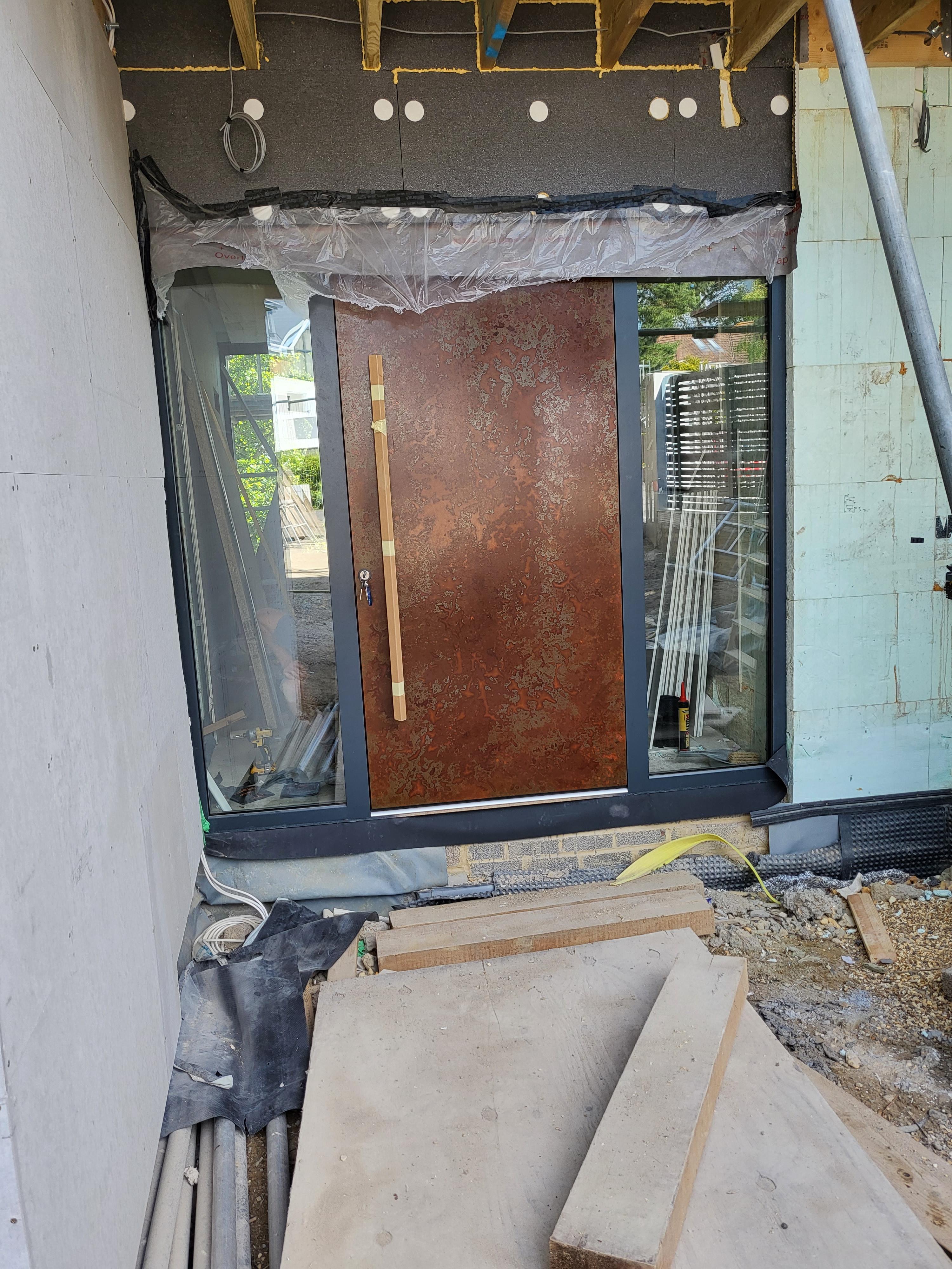
That could be fun - vinyl - but hard to believe it will quite look the same 🙂 But I may buy a piece to see if I can do anything with vinyl on my camper van as it has some rust anyway so this would blend in if they could do big sheets
-
Hi - thanks, we're really pleased with it. Yes Anthracite frame to match glazing frames etc. Handle - ha ha I don't remember, it's still covered up will have a look to remind myself what we ordered
-
Yes lots of air got in the pipes - this floor is fed from the floor above but the pipes go up into the ceiling along 20m then down about 6m so a bit of a journey. All sorted
-
Yes thanks seems most likely so on that today before itnge
-
That may be a challenge as it's all of course in walls/floors now. If only my pipe conducted electricity 🙂
-
Thanks @Temp my mistake in the typing, seems I cannot edit the earlier post. Correction - flow valves are of course on the flow side and the manual valves are on the return as per the link above
-
Oh and room thermostat calling for heat
-
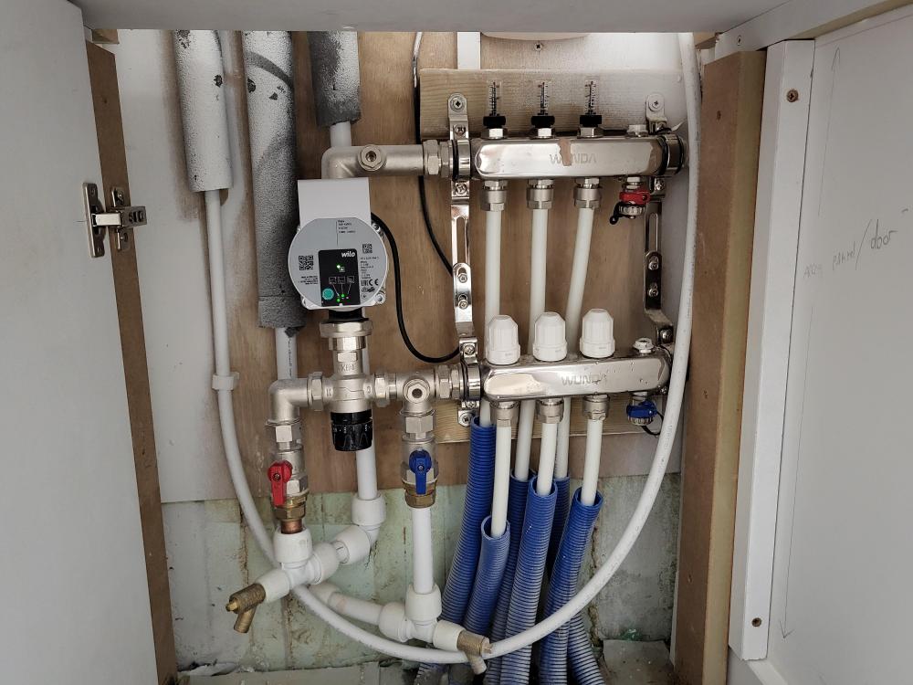
So, setup is: ASHP Buffer 4 x manifolds each with local pump on the flow after the mixing valve Return pipes collectively go through a pump Fairly new system - Wunda/Wilo/Grundfos (return pump) ASHP working fine, hot water on DHW and buffer is hot 3 manifolds OK and heating floors (well 2 I can test and are OK 1 I cannot test easily at the mo) 1 manifold (this is on a floor below the plant room with Buffer etc) has a simple setup with flow guages on the return part and manual valves on the flow (plumber & electrician figured as 1 zone why bother installing the Salus auto actuators that I have, will deal with that later). The flow guages all read "0" no matter what I do, they are pretty much fully open and the manual valves on the flow I tried either fully opening /closing and no difference. The pump is running (Wilo para) and set to UFH and low speed but I tried experimenting and no joy. I checked for air in manifold with the manual bleed and a small amount came out. What may be unusual is that the flow part would do a good pee but the return was a dribbler - implying a lot less pressure? Pump does sound like has air so I've done a few of the forced air removal things by pressing the green button in for 3 secs. If on the mixing valve I close it up -so min temp, I then get some flow guage action - but as soon as I open it up to let hot water in, the guages go back to zero Looks like an issue possibly with the mixing valve not bringing in hot supply or the zone valve looking like it is open but not really being open Can't see what else to check - would appreciate suggestions. The pressure looks like it's 1.5 bar (in plant room so slightly more presumably 3m down) Cheers for ideas - will post a pic of manifold.
-
Hi we used a combination on ours. Mars bars - these are quite cheap and flexible, you break them up of course into smaller bits, when installing don't create a nice uniform line as apparently that can potentially help induce cracking so go random! We also needed metal chairs (1m & 2m lengths) at different heights to support our 2 levels of mesh in the slab. Not sure if you get 50mm mars bars but don't see why not. To your questions - we just had a pallet delivered and used as many as we felt was needed for adequate support - they went a looooong way, we had about 200m2 of slab that was plenty Not used plastic chairs only metal
-
Nuaire MVHR Info - wall bracket
Adam2 replied to Adam2's topic in Mechanical Ventilation with Heat Recovery (MVHR)
It's been running fine though uncalibrated for a while and no issues. Integrated with home automation easy enough. Will calibrate when we get the 2nd unit on in a few weeks.