


sharpener
-
Posts
1487 -
Joined
-
Last visited
-
Days Won
1
Everything posted by sharpener
-
A booboo may have been made
sharpener replied to Post and beam's topic in Air Source Heat Pumps (ASHP)
-
IIRC when I looked into them (nearly 2 yrs ago now) the CE warranty required you to disconnect the unit and return it to their factory...
-
A booboo may have been made
sharpener replied to Post and beam's topic in Air Source Heat Pumps (ASHP)
Vaillant schematics files are here. Ask you installer to show you which one he has used, and what the features are that give independent control of the two zones, and where the VR70 wiring centre and second temp sensor have been installed. Temperature Modulating Valve. It will be a valve with 3 pipes near the manifold/pump for the UFH, and probably have a coloured top - to adjust the URHF feed temp to a lower value than the rads need. -
Is there no room for negotiation? 22% of DTX will protect down to -10C so 30% prob. to -13 or so. That seems overkill for "East Kent" unless you are high up on the Weald...
-
From my earlier researches ISTR 30% is quite a high concentration for the UK, and in particular Fernox HP-5C may be more economical, it can be used at a dosage as low as 10%, this protects down to -4C and has a specific heat of 4.15 at 55C. It is based on propylene glcol, but at a low conc. maybe the viscosity is not too bad. From the graphs it seems to be less viscous than 25% of Fernox HP-EG, which is the lowest allowable conc. of their ethylene glycol product. Who is yr HP supplier and what product have they "chosen"?
-
No it should be 8. This setting is nothing to do with the numbering of the options in the schematics file. 8 is correct for all systems without buffer vessels (not including volumisers). Buffers need setting 10. Other numbers are for boilers and hybrid systems. Re pressure drop, your system is sufficiently close to mine (which has 28mm o/d copper primaries so about 26mm i/d - and a lot [?12] of right angle bends) that I think this is not the problem and would look to the filters. IMO you should have a decent branded large area magnetic/mesh filter and NOTHING ELSE. I have a Y-strainer like yours in my rainwater harvesting system and a hard-to-see tenacious film forms across the gauze surface which causes quite a pressure drop.
-
It's well established that Type B RCDs are required with HPs that have inverter drives. What is new is that Vaillant have themselves added new requirements regarding (I think) harmonic content that means that only certain Type B RCDs are suitable - which makes a mockery of the type classification system. Personally I think this stuff is massively overdone, safety is mainly a matter of workmanship not added devices. The house my parents bought in 1953 was rewired to (the then) ring main standards with Wylex ceramic rewirable fuse carriers but I don't remember them blowing as a regular thing. RCDs and MCBs were a significant improvement but I am not convinced that ordinary domestic installations truly need surge protection or arc fault detection. /rant. IMO the HP mfrs should build whatever protection is required into the HP itself, then (a) you could connect them into an ordinary CU final circuit (b) there would be no debate or confusion in the trade (c) ppl could not undercut reputable electricians trying to do a proper job by fitting a cheaper RCD or ignoring the requirement not to fit it downstream of one with lesser protection.
-
One last thing. Vaillant have recently changed the spec for the fancy RCD you will need, previously the cheap(ish) one from Fusebox was approved but now IIRC the only one is from Haager. This topic is a whole nightmare in itself.
-
A booboo may have been made
sharpener replied to Post and beam's topic in Air Source Heat Pumps (ASHP)
That is the Basic System diagram number. 8 is correct without a buffer, 10 with. I was asking about the schematic of which there are a whole book of them depending on how many zones, what they are, whether an indoor unit and/or buffer. See other post with link to FB group. There is a recent post on there about multiple zones, you will need additional temp sensors as well if you want thermostatic control of room temp in them (Room Temp Mod = Active or Expanded). -
I would go with the wired SensoComfort if you can, as the wireless ones also come with a wireless OAT sensor and there are frequent reports of problems/error messages/solar cells needing cleaning.
-
A booboo may have been made
sharpener replied to Post and beam's topic in Air Source Heat Pumps (ASHP)
Yes it can. Provided they have fitted a VR70 two-zone wiring centre as well(!) (big shallow rectangular white box). Or maybe they have used a third-party control setup, what schematic have they used (all are in Files section of Arotherm plus FB page)? -
Try this FB group. The wiring diagrams are part of the Vaillant schematics files (in Files section). I doubt they have changed much, the VWZ Appliance Interface looks quite antiquated and I think pre-dates the plus range. Or post a query there. Which controls are you planning?
-
Not sure where you are as you post the pump performance in Spanish! In the UK the largest Arotherm plus is 12kW which is what I have. The primaries are in 28mm (o/d) and are about 10 m to the point where the circuits split into 22mm to the rads and 22mm to the UFH. The pump in the outdoor unit is very powerful, we see flow rates >2000 l/hr and it all works fine, I don't think you have fundamental cause to worry with what they are doing. If they have economised by using a cheap filter get it changed to a decent Magflow, Inta or Adey one and keep it clean. Here is a flow/pressure calculator which may be handy. The other useful relationship is 1 kWh = 860 litre-degrees i.e. 1kW = 860 degree-litres/h.
-
That's a trifle harsh. It's a reasonable thought experiment. And it is quite simple and as drawn only needs one diverter valve - though it needs a second one to bypass the rad circuit esp if there are any zone valves or TRVs. Any arrangement that will do CH, HW, both or off will need two valves because there are two degrees of freedom and four states. The standard 3 port configuration will not do both at the same time - at least not intentionally.
-
Yes. This would work with a boiler perhaps. With an HP, as well as the decrease in CoP you have also the consideration that they usually work with a small dT and a high flow rate which is a load profile you do not have with loads in series.
-
Given the temp drop across the coil, with an HP you are increasing the flow temp which depresses the CoP. Also there is the question of putting the whole heating flow through the coil and the resulting pressure drop. Your control solution with a 3-port valve would work but you also need a bypass arrangement for when there is no heating demand at all, which could be done but typical modern controllers are not set up for this. An analogy would be those radios and televisions which had all the valve heater windings in series, the valves all drew 100 (or 300) mA with variable voltage drop. It is a whole new system concept and needs designing in the round for it to work, though it did. A constant 6.3 V supply is a lot easier to design with and you do not get high AC potentials on the heaters.
-
Four sorts Stuff you put in your car - ethylene glycol based, highly toxic Stuff you put in your heating system : if ethylene glycol based (Fernox EG), highly toxic if EG based but with detox inhibitor (Hydratech Thermox DTX) then not toxic If propylene glycol based (Sentinel X600) then inherently non-toxic.
-
Even in Devon we have had periods of several days at a time below freezing. And if the system pressure falls for any reason the HP will not function. I would have preferred to use glycol, but with a 300 l thermal store the cost of it would have run well into three figures so the installers wanted to fit antifrost valves. In extremis these will of course dump the coolant which contains inhibitor and biocide but as the primaries go up over the back door I am hopeful the loss will not be too great. BTW ethylene glycol and propylene glycol have very different properties, see this thread.
-
I dimly recall advice to pre-dilute it as it is quite viscous and may sit at the ends of branches and not mix. I think you can add it to flushing machines but I don't know of a handy DIY technique.
-
Certainly but in any line of business you must get a nose for the brain-pickers no-hopers and time wasters. We once were approached by ppl who wanted to solve overheating in an electric motor. We suggested various solutions ranging from a simple thermal model in s/w to embedding sensors in some representative part of the motor or indeed in a physical thermal model (like a simmerstat). Total waste of time bc: they didn't want to make any h/w or s/w changes (eh, how was that going to work?) even under NDA they wouldn't tell us enough about the motor, the application or the production quantities they didn't want to spend any money Yes you have guessed it the overheating motors were in the infamous Sinclair C5.
-
Plausible. When it is gusty the power lines will dance all over the place and frequently short, the DNO will usually succeed in containing the effects but you may get spikes on the mains. PFC could well be power factor correction, there might be a capacitor across the input for this. They are usually self-healing but a transient overvoltage might have caused some temporary damage which registered as overcurrent. Similarly we had a glitch yesterday, the lights dipped for 1/2 second and I feared it would upset the clock on the cooker which is sensitive to these things but it didn't. Almost immediately there was a lighting flash and thunderclap so the electric storm was likely the underlying cause.
-
Similar to the two alternatives Octopus now offer for their Cosy HP installs. Seems a sensible approach to me, not everyone wants/can afford/has the space for a new HW tank and enormous rads as @JamesPa says. On the subject of survey hit rate I had 2 free full surveys out of 6 installers contacted, the others were ruled out for one reason other. One of the two got the job so for him 100%(!). I would have thought installers would want to screen clients so they are achieving 3:1 or better, or the cost and more importantly the waste of skilled manhours would simply be unviable.
-
Disagree, we had to raise the design flow temp for our HP to 47.5C to avoid using a massive T33 in one bedroom using all available space on one wall. Big lossy house like the OP's. Apart from this one rad 45 would have been doable, but not 35.
-
Rads and UFH manifolds in series?
sharpener replied to SuperPav's topic in Air Source Heat Pumps (ASHP)
@marshian proposed this earlier and some implications were discussed in this thread (jump to Jan 24 2025). -
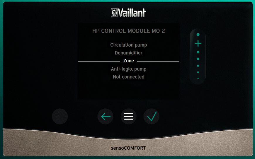
Things to try: Have you followed all the settings on the 3rd page of the relevant schematic, in particular system diagram set to 10? However I am not sure about connecting to MA1 anyway as I can't see a way of configuring it in the black controller menu using this simulator (https://simulator.vaillant.com/vrc720/at/#/simulator). But there is this in the white controller manual though none of these options seem appropriate for yr system: You could alternatively connect to MA2, with the right choice of option, IIRC it is set by default to HW circulation which is not what you want, try Zone Alternatively you can leave it on hw but set up a time schedule, which is not as good as having it follow the demand but better than having it running 24/7 Try posting a query on the Arotherm + FB page, there is a lot more expertise to be found there though unfortunately a lot of BS as well.

- 22 replies
-
- 1
-

-
- solid state relay
- ssr
- (and 1 more)
