Digmixfill
-
Posts
204 -
Joined
-
Last visited
Everything posted by Digmixfill
-
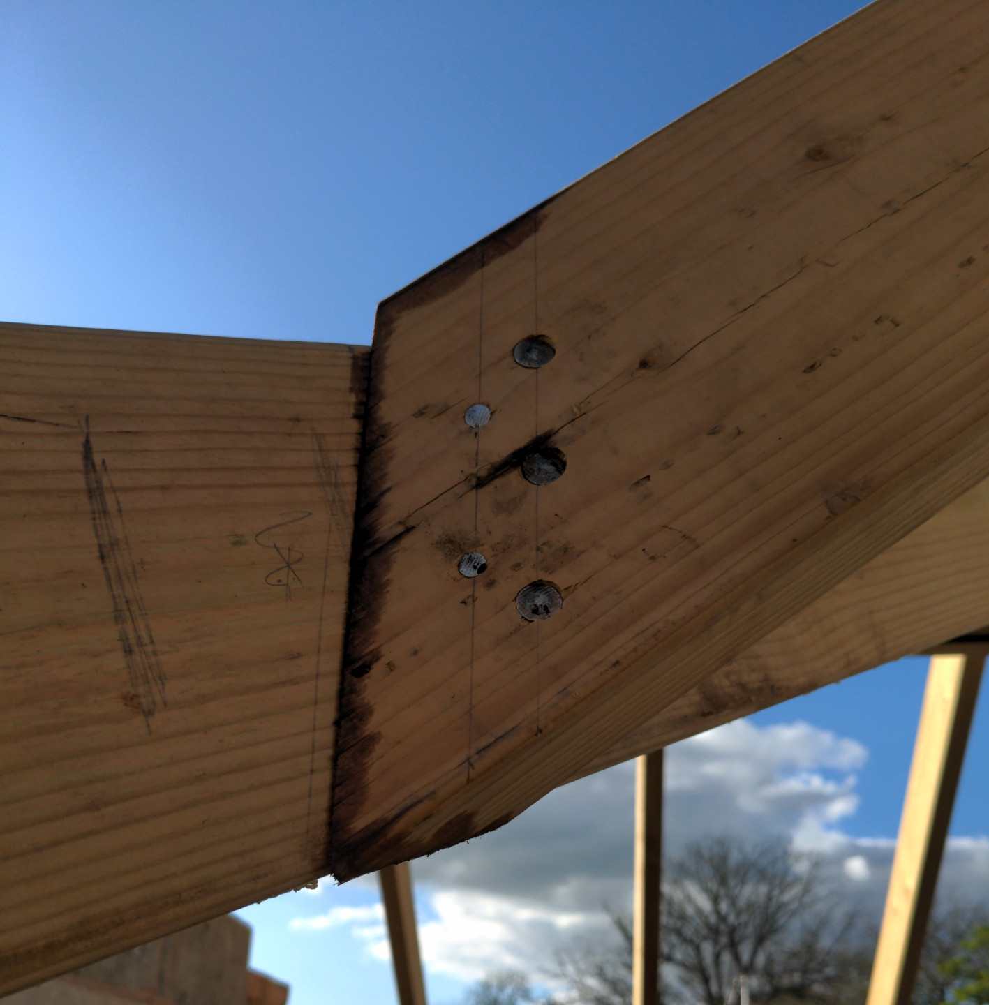
I went with a pair of locating nails driven perpendicular to the jack rafter face and three 4.5mm Ø nails at ~23° to the jack rafter face at the thickest part of the connection. All piloted in the jack.


-
Most of the internal wall and PIR is in place. Enough to be in the way. Are structural screws acceptable? If all else fails I could get something like timco index screws in place and wind them in with a ratchet spanner. When you drive your nails in, do you drive them perpendicular to the valley, perpendicular to the jack or somewhere in between?
-
I've never had to nail this type of timber connection. I don't want to make a mess of it. How far from the feathered edge should the nails be? Half way up the length of the cheek cut or more toward the uncut part of the timber? The valley rafter is a doubled up 44x142. It will need a long nail to go from the back 😯
-
I'm at the jack rafter point now. How many nails are required in a 44x142mm valley jack cheek connection? I'm hand-nailing. What size and at what angle should the nails be inserted? All of the cheeks are easily accessible bar one. The jack rafter next to the gable will be 50mm away from the blockwork. Not much room at all there.
-
Whilst experimenting, I was mindful of the plane of the roof. The adjustment timber brings the rafters in to the same plane and down to the same angle as the unadjusted rafters. I chose stainless screws for the glue/timber connection specifically because they will bend and not snap. With the cascamite and the large bonding surface area, the connection should be stronger than the wood itself. I'm not using nails to hold the rafters themselves in place. I'm using M8 stainless coach screws through the rafter into the wall plate. Pull-out/pull-though force for each connector is considerably more than skew nails.
-
I spent a while experimenting with different things and I've opted for a lump of C16 under at least 2 rafters. A handful of stainless screws and once i've finished cutting the rafters and levelling i'll finally fix with cascamite and screws. The timber adjustment pieces get gradually thinner to follow the adjustment required. This gives me the same birdsmouth cut as the unadjusted rafters, so less mucking about marking and cutting.

-
By that do you mean you would lift the wall plate itself, or fix the shim to the wall plate?
-
Internal walls are in the way for an end to end measurement, but I measured the diagonals of the largest room. It's around 4.5m long and 4-ish-m wide. One diagonal was a good 5cm longer than the other. Argh, that's not how I roll. It would bug me for the rest of my days if I didn't try to level things out Which is preferred - glueing and fixing the shim to the rafter seat or glueing and fixing the shim to the wall plate?
-
I'm converting an old brick barn. The original walls are all over the place. I have built a new inner leaf following the best line I could. Everything is a work around By the time i've stuck insulation under the rafters I won't see any evidence of rafter adjustments. Would a shim cut from the C16 wall plate offcuts be sufficient? Just cut them to the width of the rafter and glue & nail underneath the seat? I'll check, but the odds are against square.
-
It's definitely the building being somewhat less than square. The wall plate hasn't budged at all. At the worst point the span is > 75mm less than the opposing side. You would keep the 60mm birds-mouth seat and shim the wall plate height for each affected rafter?
-
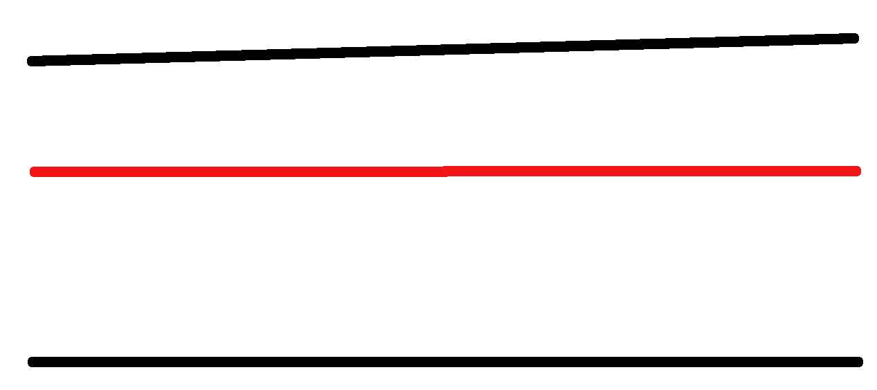
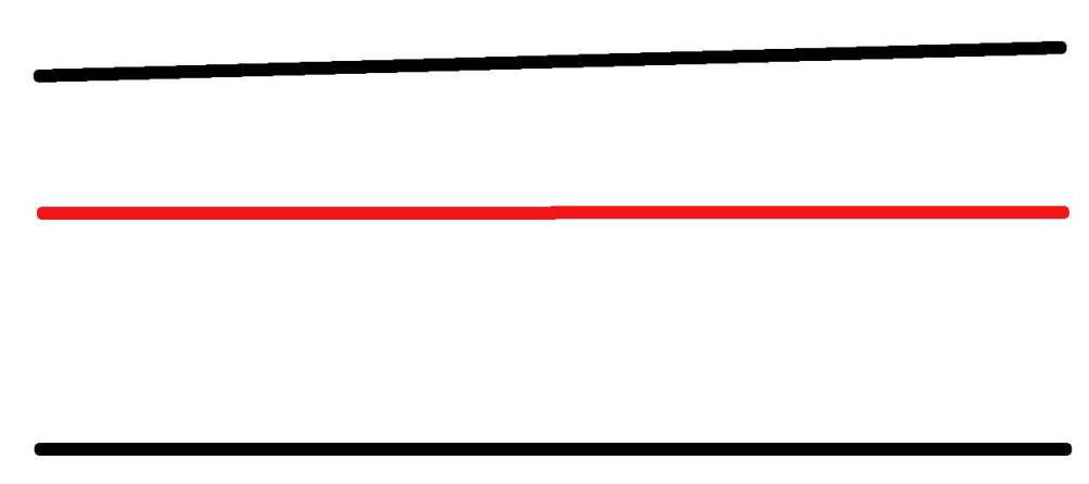
I've run into a snag with my cut rafter plan. My ridge beams are level, and the new wall plates are level, but I didn't measure the span distance between the ridge and the walls all the way along. I foolishly assumed everything would be parallel - I really should have known better. One side of the roof is proceeding as expected. 50x150mm rafters at just under 35 degrees with a birdsmouth seat length of 60mm. The side with the progressively diminishing span isn't going to work at the shortest end. The angle changes, and the projection of the rafter at the foot is quite a distance away from the eaves edge. If I put a piece of 22mm timber under the worst offending rafter with the current birdsmouth cut, everything works, but i'd obviously need to use progressively smaller bits of timber on the other rafters. If i reduce the birdsmouth seat length, I can get it to work with the existing wall plate, but i'll be heading toward 30-35mm seat length. What is the accepted minimum seat length? I can only find details for maximum birdsmouth depth. An exaggerated plan view of the roof attached. Red=ridge beam Black=eaves. How would you resolve this?
-
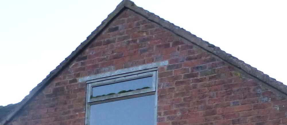
Installing a roof window at wall plate height?
Digmixfill replied to Digmixfill's topic in Skylights & Roof Windows
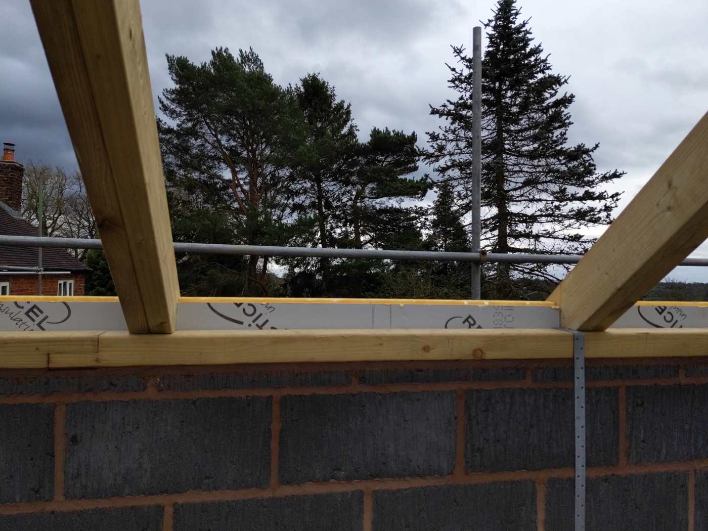
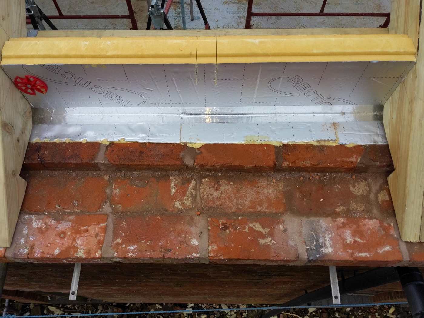
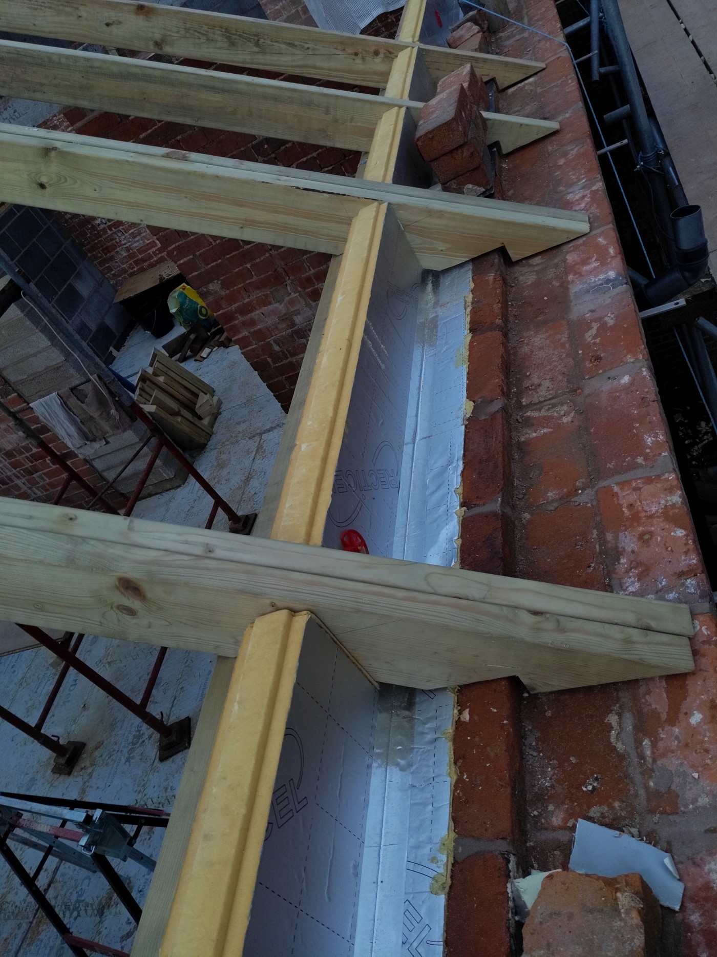
I think there will be enough distance between wall plate and gutter for flashing. We have very deep corbelled eaves. It's a maybe. Not sure how we would stand with planning for that though. Worth an email to them to see if they have anything. I was planning to splay top and bottom. Is splaying the sides worth the effort?? Pictures might help:


-
Installing a roof window at wall plate height?
Digmixfill posted a topic in Skylights & Roof Windows
The typical roof window install is cut a rafter, double up the rafter either side of the opening and install double horizontal timbers to carry the cut rafter. Image from Fakro install doc attached. All of the installations I can find show installation in the middle of a roof. Our upper story has 1.6m walls. I want to install the window as low as possible, as close to the rafter wall plate as I can. Fitting the lower doubled up horizontal timbers right next to the wall plate takes up space which i'd like to avoid. Anyone installed a roof window low down in a roof, up against a wall plate?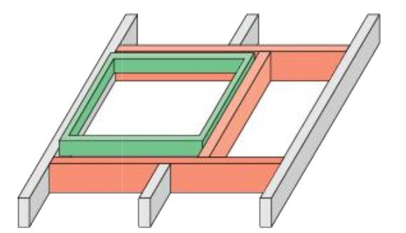
-
Valley rafter installation height?
Digmixfill replied to Digmixfill's topic in Roofing, Tiling & Slating
If I'm going to screw up anywhere with the roof it will be the valley rafter. If the height difference to the main plane is in the hardly noticeable class for my particular case, I'll cut the bird's mouth as the other rafters and adjust if necessary. Thanks Oz -
Valley rafter installation height?
Digmixfill replied to Digmixfill's topic in Roofing, Tiling & Slating
My common rafters are at 35 degrees, and I expect my valley to be somewhere near 26 degrees. Are you saying that if I cut the heel height of the bird's mouth the same on the commons and the valley rafter, the valley will naturally be lower than the main plane of the roof? -
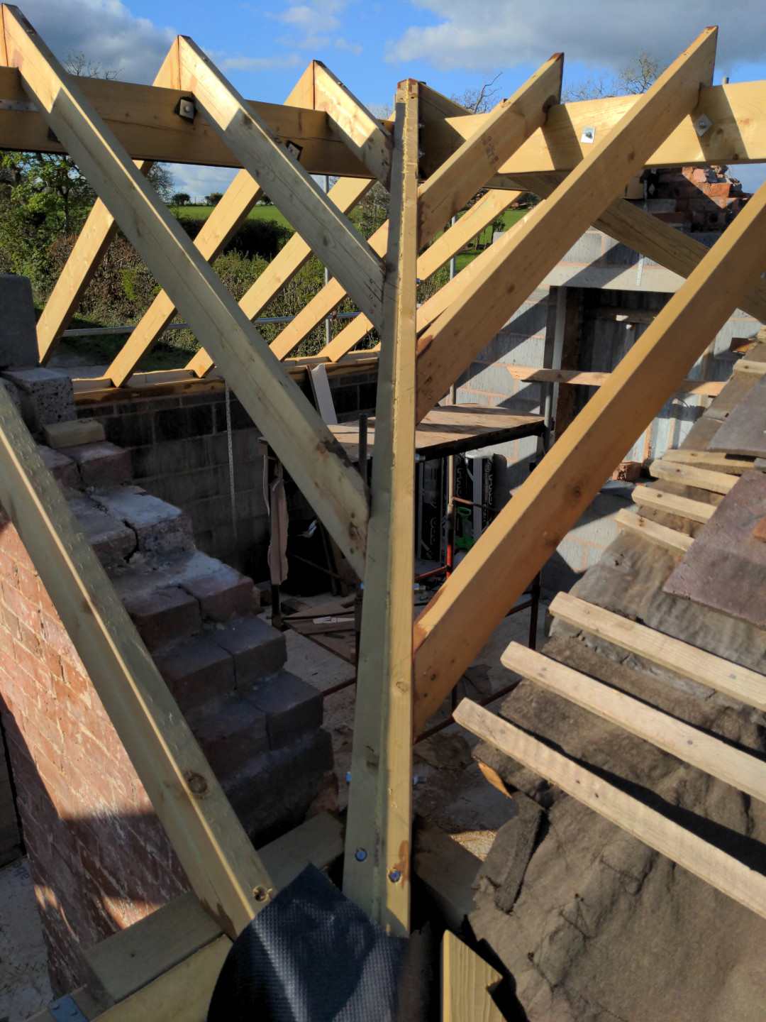
Merry Christmas everyone. I have two roofs at the same pitch and height that join with a pair of valleys that will have valley tiles. Common and jack rafters are 44mm wide, and valley rafters are doubled up. I'm looking at valley rafter installations, and I see some valley rafters set at the same height as the commons and jacks. I see some where the jacks are slightly higher than the valley rafter, so I assume the valley rafter is set lower than the commons in this case? What I have failed to find is any information giving an indication why either variant is used. Is there a reasoning behind the choice?
-
I'm working with timber span tables and using the ".75 but not more than 1kN/m2" column. 600mm spacings are acceptable for the span I have using 44x145 C24. I can get 453mm to work with equidistant spacing, but I still have the irregular valley jacks. We don't have any gable ladders. Just a lump of tile as undercloak and a wet verge. I'm thinking of using a kytun verge when it all goes back on, but with the same 50mm overhang.
-
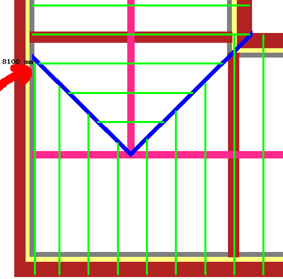
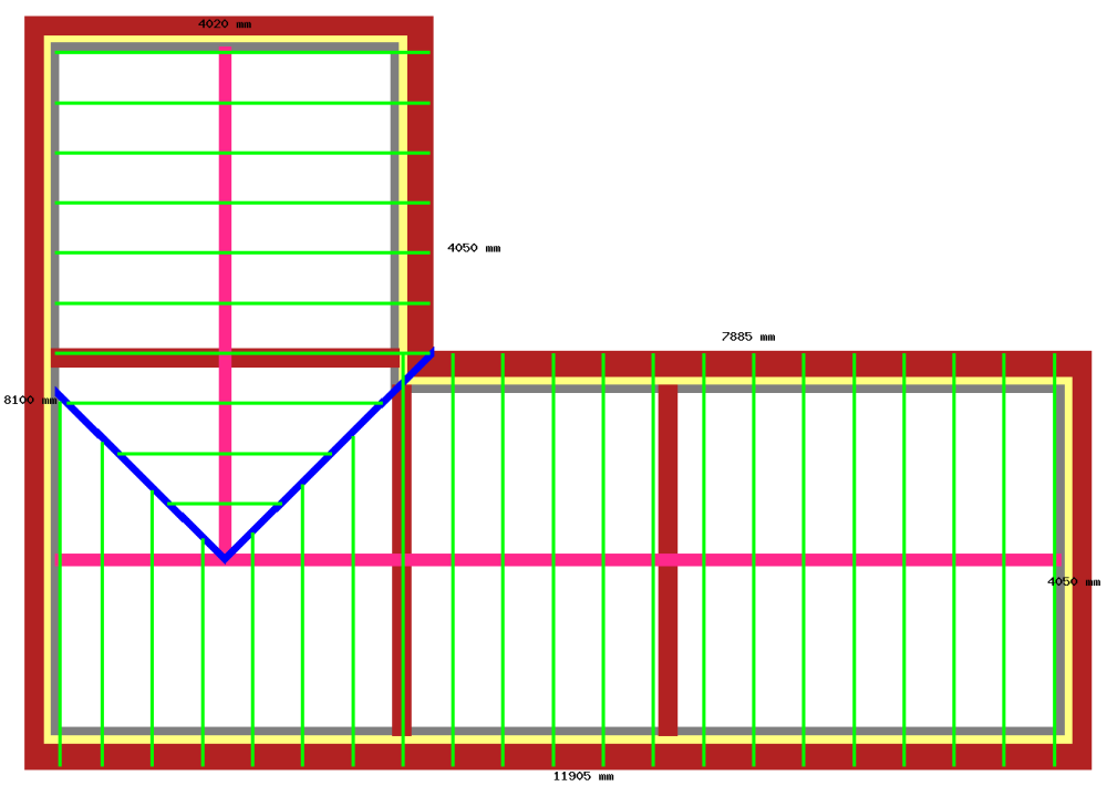
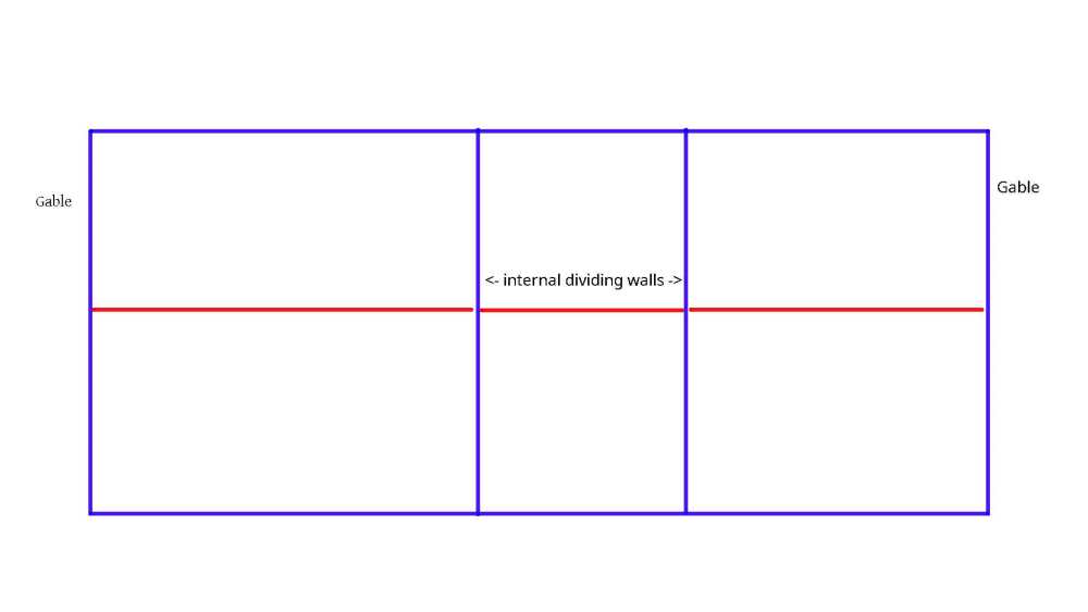
I have three gables in my roof, and ridges run from them to a pair of valleys. I'm playing around with rafter spacing to see what fits. If I try a centre spacing of around 592mm and space off from the gable rafters toward the valley junction, I can get equidistant spacing, but the valley jacks are irregular. If I start from the valley junction and space outward from it, I get regular valley jacks but have additional gable rafters at the ends. Any thoughts/preferences? In the images grey = internal block, yellow = PIR, pink = ridge beams, blue = valley rafters and green is cut rafter. Gable outer walls and internal dividing walls are 9 inches thick, and corbelled eaves extend around 12.5 inches.


-
Rafter spacing with internal dividing walls?
Digmixfill replied to Digmixfill's topic in Roofing, Tiling & Slating
Building control need the structural engineer's paperwork and they already provide approved rafter span tables. If I where creating some exotic roof style, then it would be prudent to involve them at an early stage, but this is a simple change that results in better roof insulation. Our BC inspectors have so far been really helpful and very accommodating, especially when making improvements. -
Rafter spacing with internal dividing walls?
Digmixfill replied to Digmixfill's topic in Roofing, Tiling & Slating
Everything has to comply with building control, so I don't think changing a purlin to a beam will make any difference to them as long as everything is done correctly. The external look of the roof will not change, so planners won't give hoot about it. -
Rafter spacing with internal dividing walls?
Digmixfill replied to Digmixfill's topic in Roofing, Tiling & Slating
I'm still undecided about the insulation between the rafters. It will be either PIR or mineral wool. I don't mind having to trim odd shapes and sizes. It will be a pain, but in the scheme of things a small job. Roof detail in the plans states "existing", and existing is rather rotted and worm ridden. Took the opportunity to change the roof to ridge beam and vault the lot. Rafter tables suggest we can use any spacing up to 600mm. -
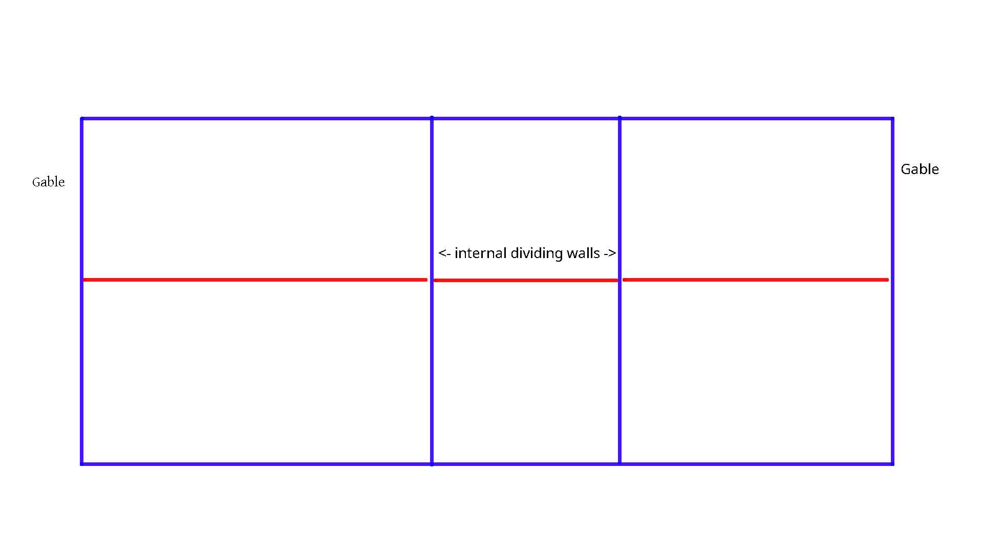
A rough layout of part of our roof is in the attached diagram. A gable at each end with internal dividing walls, with a separate ridge beam for each room. I'm aiming to place insulation between the rafters across the top of the dividing walls. There will be a service gap and counter battening with more insulation below, so rafter spacing doesn't have an effect on plasterboarding etc. I know that the end rafters need to be spaced from the gables with blocking and restraint straps, but i'm unsure what to do spacing wise around the dividing walls? Also, when starting fixing rafters is the best plan to place one at each gable and lay a string between those to get the best line? My plan is to start with an assumed 50mm birds mouth seat with the assumption that I can adjust in-out from 35mm minimum to 1/3 rafter depth maximum.
-
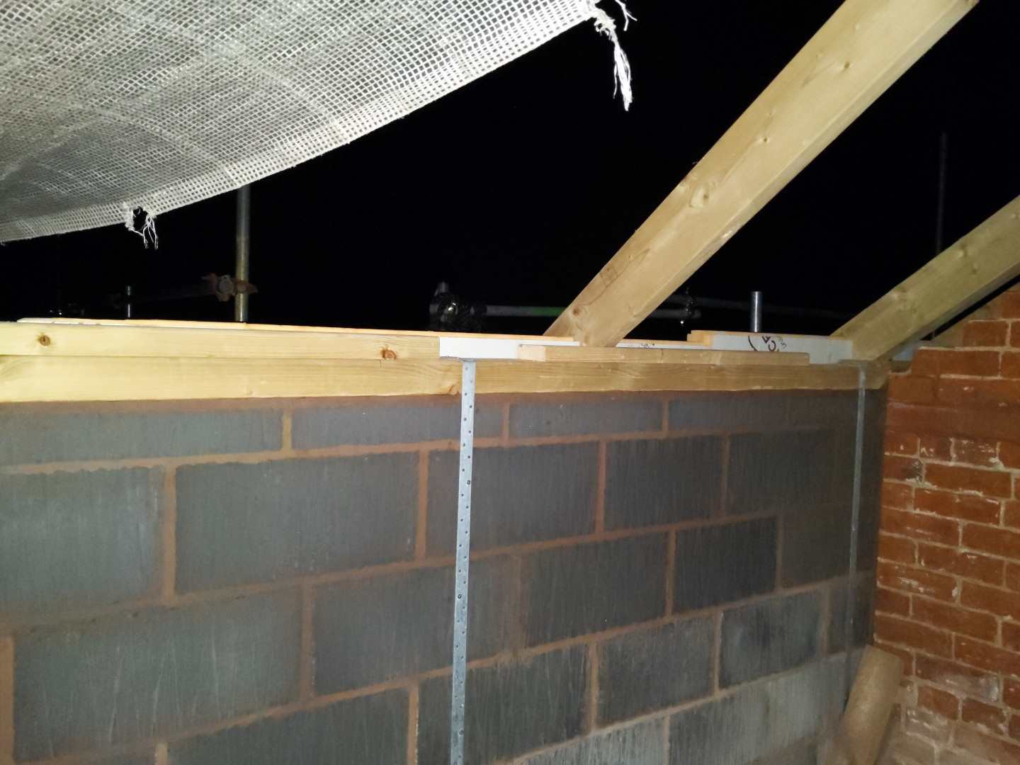
Does having a narrower top section to a wall plate, that might not be flush with the inner face of the lower section, affect the fixing of the restraint strap?
-
That's good to hear. It's room in roof. Wall plate, ridge beam and rafter is all I have to play with. I cocked up one calculation leaving an additional 25mm gap. I'll have to grab a 100x100mm wall plate for that section.
-
Bed and level the wall plates, but then knock them free of the mortar so that they are movable?