
zoothorn
-
Posts
4747 -
Joined
-
Last visited
-
Days Won
3
Everything posted by zoothorn
-
Hi Peter. Thanks for this idea. I passed it by earlier/ didn't see it. I pretty much understand it. Mostly. Conduit.. is heavy guage metal pipe? So cutting this would need some chutzpa is my first concern. Im only partly on board though. Do these conduit bits hang on the studs prior to placing the ledger board over & on? Sort of like my standoff heat stove barrier? If so, the thing that I'd surely find trickiest (however this ledger board is fixed) is due to the wavey wall, getting it fixed on perfectly vertical. In order for the rest of the timbers to sit correctly, & the deck level, getting the first main board onto which it all attaches vertical (& level too).. seems really critical. I just don't see how I can do it, even measuring say 8x individual conduit bits for their individually deep places. It's gonna rock, its never gonna be vertical. However good I do this idea. Each wavey wall 'trench' you see.. is slightly different. Thanks Zoot.
-
@Onoff great help there. Come to my rescue again! The ledger board's solidity, I'd assume dependent upon not hitting the block's mortar.. & not going all the way through (or the fischer gubbins will fall into void). And the 'pacific ocean' render: on the 1st wall face, thankfully the front of house, Mr. Render did a cracking job: subtle contouring (blends like a boss to adjacent old stone cttg shell). But he went a bit nuts on the 2nd & 3rd. 2nd = my balcony face. In retrospect I should've asked him to smooth a 6x2x4m ledger board area. But had no clue at this stage. Resulting in a very wavey 14" x 2" high "waves". Me, attatching a ledger board to this, well... not a hope in hell. Both of these 'tricky' aspects then, plus the legs holes idea (finally understood!!) fairly critical re placement & leveling/ plumbing.. makes this too tricky for me too. So it's sensible to get in my pro chap to do these two important jobs. Then I'm away. Thanks. Zoot And the
-
Morning chaps, sorry for delay, elderly folks = priority. Ok thanks I understand a wee bit more. But Im still a heap behind. Even assuming (as I might have, as I did) Peter meant 6x2.. I still cannot understand it. Thing is, Im still not a builder, even though I've now built things. So I can't comprehend many a conversion in "Builder"! I did use the figures of 6x2 (assuming 150/50 were dims I could only think corresponded to 6x2 & this therefore was -probably- reference to timber). But even still "put it on a 6x2" is meaningless. So I'm only 3 numbers further on in understanding.( Is this a beam? Is it an offcut to rest the pillar on? something else?) So, at the first juncture of Peter's paragraph, Im stuck & cannot understand a word of it past 150/50 on line one. Yes I understand the drilling of 50mm. I get the insertion of a scaffold section. But anything onward... I'm looking at a blank sheet of paper. I have tried hard spent 20 to 30 minutes trying to deciphr this paragrah to no avail. You can see maybe how far behind I am? I'm back a mile going " HEY... WAIT! I'm stuck here!" with everyone else (with great intent) running on ahead. I'm still an idiot, is best way to consider me, if you will. Thanks so much, Zoot.
-
@PeterW Im not quite understanding "Connect your legs to a 150/50" What this 150/50 is-?
-
Just to say I am doing as much as I can in prep (pic below). The ledger board being fundamental it seems, due to my wibbly wall is proving a tricky prospect/ 1st hurdle. I just don't know how to tackle attatching it really fully securely. Ideally obviously, this (6x2") x 3300mm section of wall should really be flat first. How to flatten it then. Either I removed the 'hills' somehow ( seems a b'stard of an idea), or I raise the dips & add render or whatever, to form a flat long rectangle ? Is this adding idea feasable? Thanks, Zoot.
-
Typical eg of how someone who works in inches, cannot use mm's figures to picture anything, because, of the huge numbers involved. Eg: 7 ft is immediately imagined. 2130mm is impossible to imagine. Zh
-
Aha ok. I was sort of on board with this part then. Apart from my daft notion the pole width would be the 100mm figure. Ok, got it: so 350mm sticks out. But from here on I'm not understanding. For eg, I don't know what a " 150/50 " is Peter refers to you see ( a bit of timber? 6x2"?) so I'm unable to comprehend anything onward/ the paragraph. Thanks, Zoot
-
Hi ProDave, tbh I'm now not understanding the idea at all then. All I thought/ the only part I could gather, is the use of a section of scaffold pole, inserted into the base of the pillar. I might assume the pole diameter being 100mm. Therefore I would need a bit diameter, of 100mm. But you say here not. I am as usual, completely lost. Apologies. Zoot.
-
@PeterW Hi Peter. Thanks for this. I'm partially on board with the idea. I've googled forstner bits, & can get a 100mm £16. Are these ok, & useable ( without jumping/ juddering) with an electric hand drill? I get the idea of making the hole in the post base, but not as deep as 450mm (I'm not quite sure how, with drill & a bit). I get the idea of inserting a bit of scaffold post into hole. From there on.. I'm completely lost, sorry! Zoot.
-
Hi ProDave. Totally on board with those two changes. Good, glad that idea ( youtube) approved.. spent all afternoon on it taking notes & working out xyz/ how & why things done. What about their pillar fixing idea? IE pillars on 8x8" round pad set into ground.. with a rebar sticking up to 'fix' ? Simpler surely than hefty 150x150 galv shoes, type I used onto my huge concrete cabin pads. These would need like a 12" min round concrete something for their 2" flange with 4 fixing holes. Surely overkill.. & would look nastier too. Thanks, zh
-
@Onoff Your thoughts always welcome: following joe90's lag board/ start tips, I wonder if this design is a good'un to use/ follow. Seems likely the most cost effective approach. And some bits like the notched pillars, I did on the cabin base. Plus only 2 pillars needed maybe. Finished "deck" @ 18 secs. Briefly/ best to pause @ 0.18 Zh
-
Hi Joe90. Thanks for this. So step 1 is back beam fix to wall with rod & epoxy.. then how would you attatch the other 3 timbers (assuming these would be step 2) if they're unsupported? A naiive question most probably. Zh
-
Hi Modster, I would have done just this.. but extention is a foot lower than should be ( dont ask) so this room's balcony, already low due to the ceiling of workshop below (1850mm), is a full foot lower still. Meaning a rather odd very low balcony to make, but any lower... would be getting super-silly. Thanks, Zoot.
-
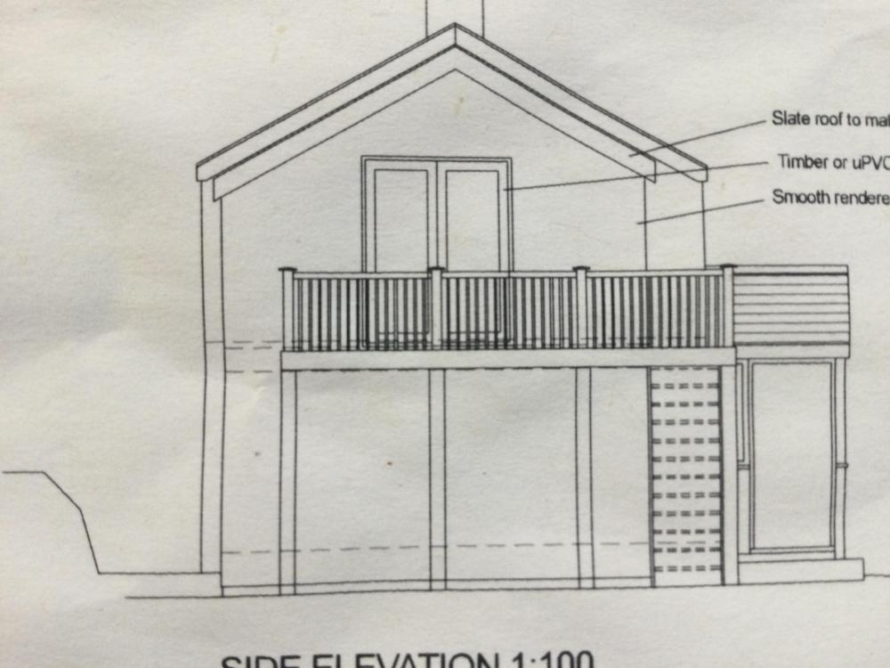
Hi Peter. Ok thanks I'll note this. 96mm balls.. maybe a bull will be sitting out on my balcony then. One thing I was going to ask you: If you can see Im leaving off the steps (my computer plans show above): do I need to get 'permission' to effectively do 'less' or as it's just leaving a chunk off, just assume fine & crack on? Thanks, Zoot
-
It is but frame is the inner wall though. I have a block outer wall. zh
-
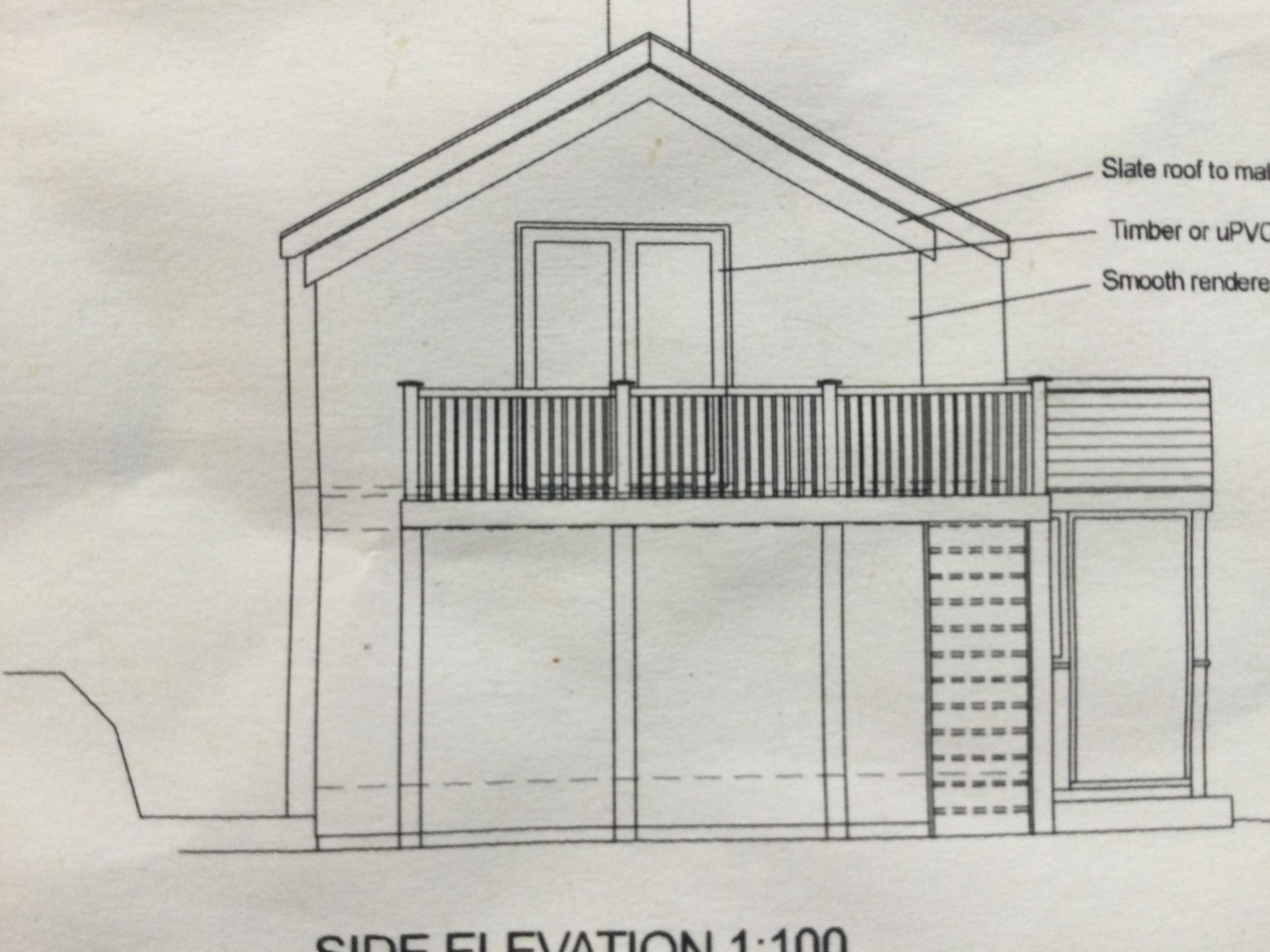
Goddam regs. Im only head high with the balcony deck due to builders 1 ft too low infuriation. Now this will affect my view a wee bit more than I thought. But basically up to handles' height. Sitting out on it will be affected by this excessive height though. Argh. Maybe I could do X shaped ballustrades, to open up the view a tad more. Thanks J.
-
Hi Modernista, good point. But A) I have no choice as doors open outwards (in retrospect daft, as walls fairly thick thesedays.. purely a novices decision ). And B) like so is on the plans submitted & agreed to. It will partially affect the view only, above handrail is the main view across valley 2m, & big sky, below isn't too much to squander: a road, sheepfield, trees. Glass... far too costly & not cottagey enough. But a keen point. Thanks.
-
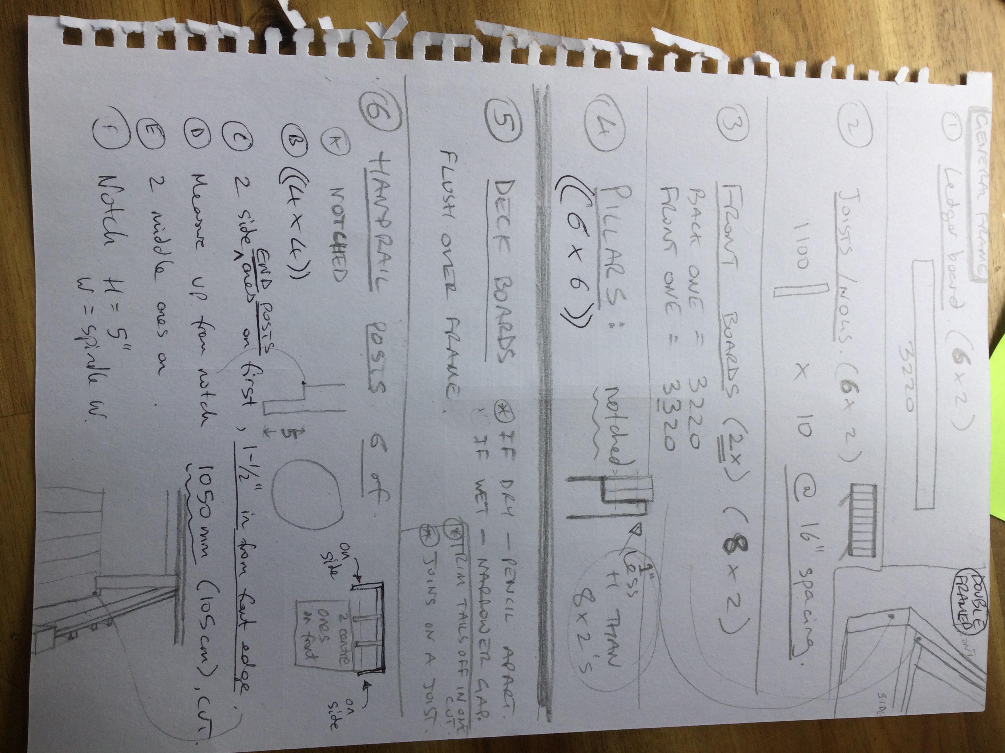
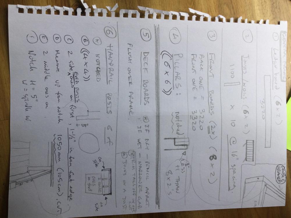
No I didn't trespass.. taken from a very convenient close side road. Anyhow SO obviously a holiday house. I did snooping only yr honour. @joe90 Dims (firm) are: L 3320mm x W 1250mm These are what I have PP for; well, what I have PP for is more/ steps too/ like this..
-
Well on my PP drawings it had the steps up, so I am guessing a bit right now @ L 3200mm.
-
I'm sure it will. I think I might have put in for even 1300mm, being tentative thinking I'm never likely to get PP for it.
-
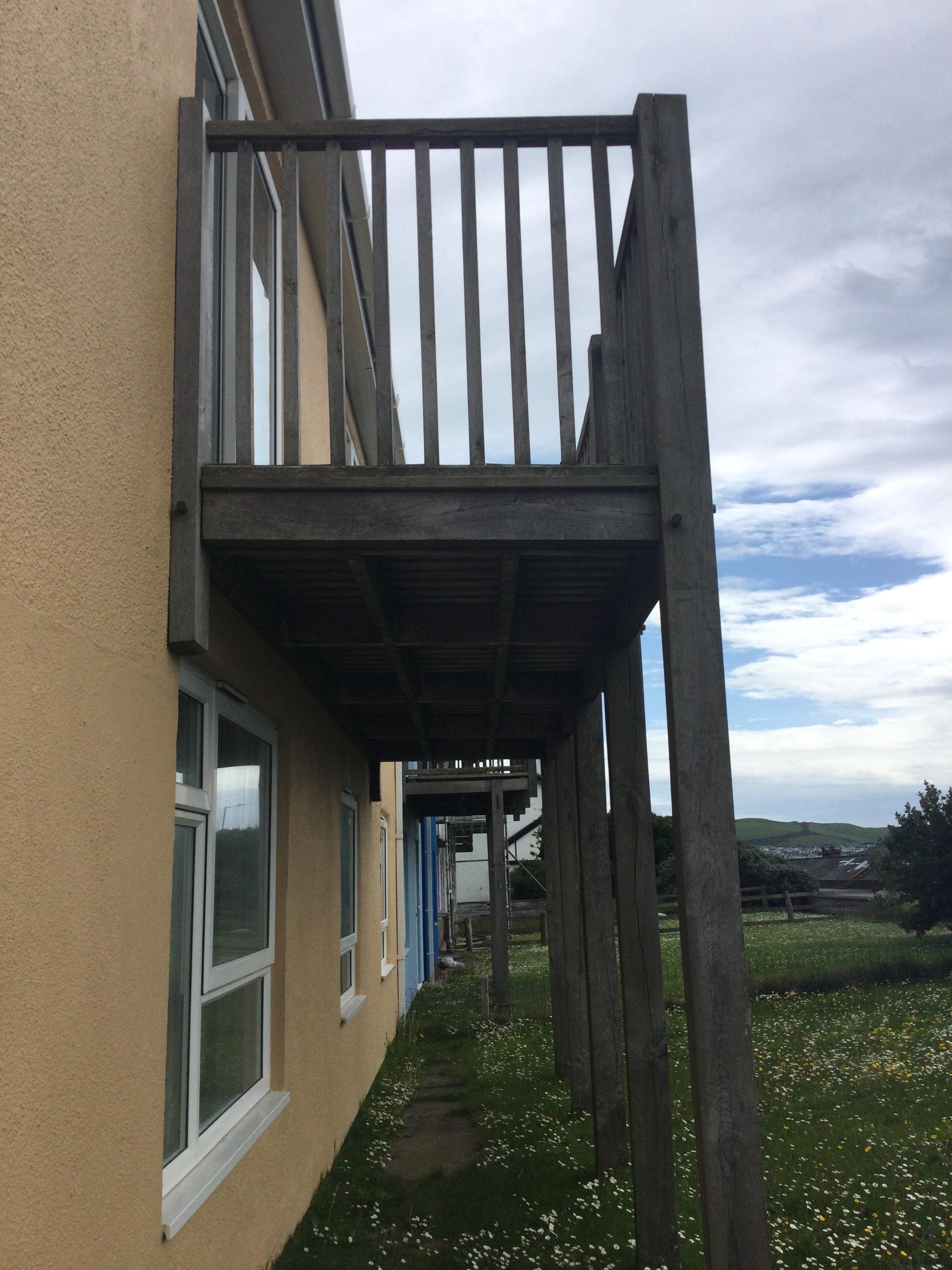
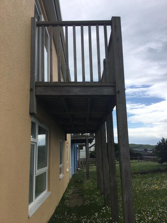
I have this underside photo eg, giving me idea of the longwise beams A to D. But it seems to have no beam A.. but instead 2 side vertical struts fixed to the wall, up @ balcony level.
-
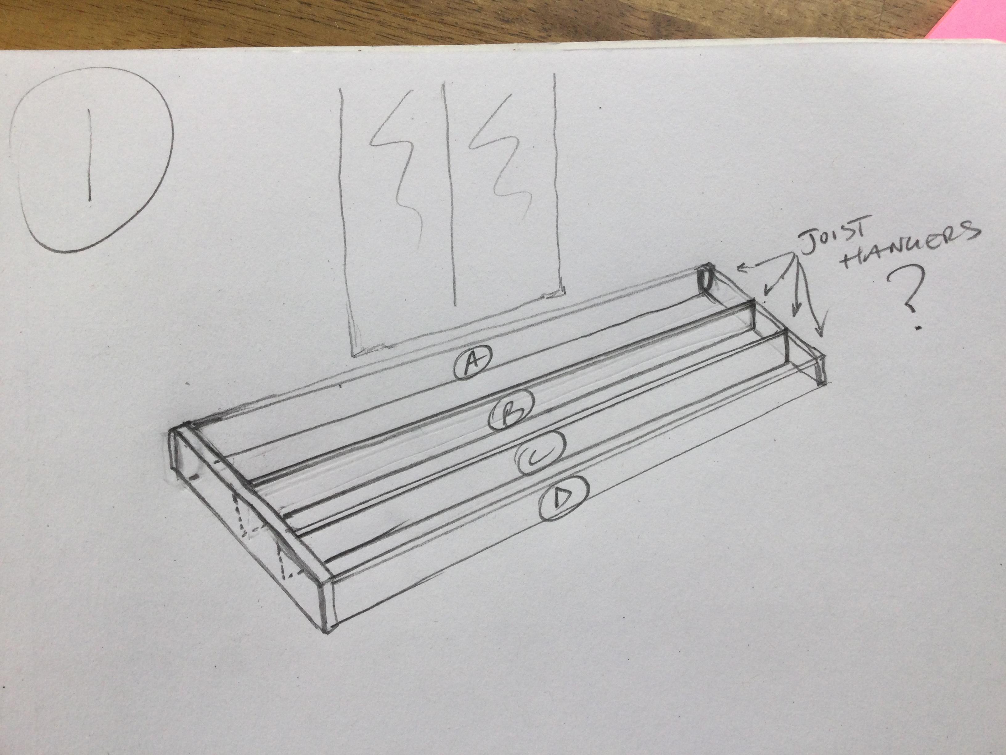
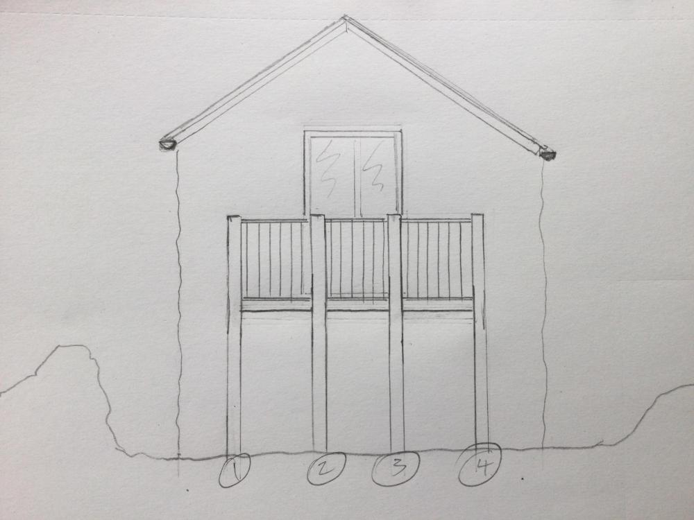
I have Joe90's idea of beam A here. And some form of a frame here A,B,C,D.. but this doesn't follow the photo eg. Tbh Im stuck at the first fence! As how could this frame be supported, so it needs 2 pillars before B, C, D.. maybe.

-
Ok balcony to be 1 pillar less than the photo eg. This eg I thought (stepped it out) was 1400mm Depth. Is that an average UK balcony D would anyone know? Thanks zoot.
-
Hmm.. from looks of it I think he designed that one when he was drunk. I think the curvy one looks miles better. Anyway I mustn't digress, car design could polax my thread!
-
Pininfarina.. well well I never knew had any doings to any uk car. I can see the difference this makes, as never once has any mg caught my eye, but yours.. just does. What engine? I think a MG gt-? & 60's by looks of the plate?