
Leaderboard


Popular Content
Showing content with the highest reputation on 06/11/16 in all areas
-
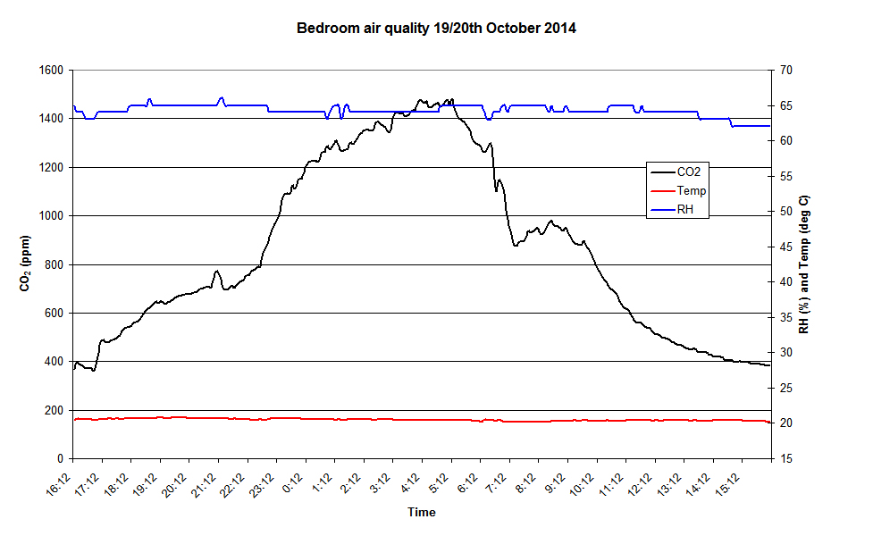
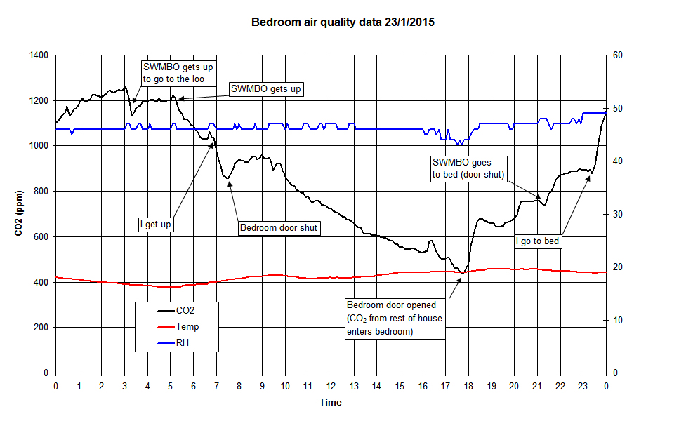
Thanks for digging that out. I have the graphical data from that bedroom air quality measurement: and also a later measurement I took where I annotated the plot with some event details:
 2 points
 -
Having spent a fair bit of time reading through old posts, I thought it would be really useful to actually capture some of the most useful content, written by people who have actually installed theses systems themselves. NB there are a number of different suppliers of the components required. These suppliers will often offer a no obligation, free design service. Some custom builders take advantage of this service, and loosely work from that base design rather than a blank sheet of paper. Horses for courses. Firstly, JSHarris from Sept 2015 "It is, without a doubt, far easier to DIY an MVHR fit using semi-rigid ducting and a radial system ... in terms of ease of design and fitting radial semi-rigid wins hands down. Where it loses out is price, as the cost of the ducting, fittings and plenums is more expensive than a non-radial rigid duct system ...The only other downside I can think of is that adjusting flow rates when commissioning the system is a bit of a pain, as you keep having to move between changing the restrictor rings in the plenum and re-measuring the critical terminal." " The spec was pretty easy, as all I needed to check was that I could get the flow rates needed for the critical rooms (those subject to building regs max extract rate requirements) without exceeding the max velocity limit in the ducting of 2.5 m/s. In practice you can go over 2.5 m/s when on boost I've found, as the duct noise doesn't start to get intrusive until around 3 m/s. These flow rates were just from the building regs requirements in Part V.As a double check I looked at the whole house trickle ventilation rate from building regs, but that turned out to be unimportant in terms of system design if you have terminals in every room, as the flow velocities in the ducts are very low for trickle ventilation.I designed the layout of the terminals so that the air had to travel the longest path from the terminal to the extract point in each fresh air feed room. In those rooms the extract point was the door (specifically the gap under the door) so the fresh air terminals were fitted diagonally opposite the door in most cases, and usually in a corner that might otherwise be a stagnant air pocket. I didn't bother with detailed duct loss calculations, as I started doing them for the high flow ducts (kitchen, bathrooms) and quickly realised that for a house of our size the ducting was more than capable of delivering the flow rate needed without incurring either high losses or excessive duct air velocity.I ended up just running the ducts by the easiest route and doubling up on the kitchen extract duct (two parallel ducts to the same terminal) to ensure I could reach the high extract rate on boost. In practice I'm pretty sure that a single duct run would have been OK.I fitted the manifolds as close to the MVHR as possible, to minimise the length of 150mm duct needed. I doubt this is really critical, as a 150mm duct will flow a lot of air, but it was pretty easy for me to put the manifolds close to the MVHR. They need to be somewhere where you can get easy access, as when setting the system up you'll be fitting throttle rings to the ducts in them. Some of my shorter ducts are throttled back to the smallest hole in the ring, which is something like 20 to 25mm diameter, so that may give a feel for how little air is moving through these ducts most of the time.I set the system up with a hot wire air flow meter set into a 100mm diameter bit of duct attached to a 150mm duct adapter to make a home made cone to fit over the terminals. I put some felt around the bit that would be pressed to the ceiling to get a better seal and to prevent scratching the paintwork. The flow meter I used was a Testo (the previous version of this model: http://www.testolimited.com/testo-405-thermal-anemometer ) purchased from ebay secondhand for around £30, but still in cal. This made it useful for leak testing around the house as well, as the sensing probe is small and very sensitive to low air flow rates. Here's a photo of my test setup: Ventilation test method.JPG 10.35K (not accessible) I adjusted the flow restrictors to get the right rates on boost to start with, to comply with building regs extract requirements from kitchen, bathrooms, utility and WC, then balanced it on trickle ventilation rate by adjusting the flow rates on the fresh air feed ducts. To fine trim it and get the feed and extract matched I adjusted the fan speeds slightly in the MVHR, so in trickle mode one fan is at 25% the other is at 28%, just to overcome a small imbalance overall.Setting the MVHR up was a bit tedious, with a lot of running back and forth and changing throttle rings, but at least a radial system isn't as interdependent as a continuous duct system, where adjusting one terminal upsets the flow rate of other terminals that have already been adjusted on that duct run. There is a tiny bit of interaction on the radial system, but very little I found, and it only affected the boost rate extracts.The whole house ventilation rate on trickle was measured both by summing the individual duct rates and also by measuring the flow in the fresh air feed and exhaust air ducts. These are 150mm diameter, so I drilled a small hol in the side of them, big enough to take the flow meter probe (about 12mm I think) and measured the velocity in those ducts directly. I then calculated flow rate from that and compared it to the sum of the individual measurements to make sure they were about the same.I found that the flow rates fluctuate a fair bit with very small outside air changes, so you have to average a few readings to get something meaningful. Even a light breeze will cause the ventilation rates to change by 50% or more up and down over a period of a few seconds, as the pressures in the ducting are pretty low and easily affected by small changes. Ideally you'd do the testing on a dead still day, but they are few and far between, even in our sheltered location." SecondlyDeclan52 from November 2015, working from a component Suppliers plan: "As far as installation goes, when you have signed the deal and paid for the goods you will get a plan showing you the duct layouts and where the vents need to go. Just make sure you get accurate measurements of the unit and make sure it will fit. There are access holes on the top and side on mine so you use what ever one suits your build. Double check it fits as his duct run layout will be from this spot. You will have 4 pipes to and from the unit. Feed and exhaust from outside so you will need vent tiles or wall vents whatever way you are connecting to the outside. The other two are the fresh air back into the house and the extract from the house. You will have a larger diameter pipe maybe 150mm from the unit to a manifold maybe a meter long depending on your layout. From the manifold then it will have a duct going to each extract. They basically twist and clip in very easy to do. I had the full 50m reel downstairs between 2 trestles and a pole through it and just pulled the duct along to where it needed to go. Leave a bit extra just in case and you can trim it to size when it's all in and secured. Measure all where your duct ends are and record this so when you are cutting the holes in the ceiling you know the exact spot where they are. You can use a hole cutter or a pull saw whatever suits you. Keep the system off till all the work is done or it will get clogged up with sawdust and all the other airborne materials. Get his flowmeter and adjust the vents to suit. Some adjust at the manifold others on the ceiling. It's def not a hard job to do just arkward as you are wrestling with a 20m length of duct that never seems to want to go where you need it to go. Get all your ducting in first before the plumbers or sparks arrive as it will make your life easier. Both plumbers and sparks will want to be first to make there routes easier but look after number 1 and get in first. If the ducting and manifold are in a cold area like the eaves you will have to cover the ducts and manifolds with the like of rockwool or you will get condensation in them And finally, Bitpipe, from March 2016: "Just completed the plenum side of my installation using 65mm internal radial duct, through luck more than design I've pulled it off but there were more than a few head scratching moments. So, where to start I used BPC who did a design (which I loosely followed) and supplied all materials. Our frame was already locked at this stage so I had to work around what was there and some issues only became apparent when the frame was up. If you're still at design stage, give first thought as to where the MVHR unit goes, you want to minimise the runs (typically 160-180mm steel radial duct) from this to the external vents (which should be on the same wall to minimise unbalancing due to wind. 1.5m horizontal separation is the recommended minimum. Then think very carefully on where the distribution boxes go (one for extract and one for supply, usually sit them next to each other) - note that these vary greatly depending on the manufacturer, some are boxy, some are long and flat. Some have ports on all sides, some just on one. You want to get them reasonably central so that you minimise very long runs but this may not be possible. Some are designed to sit in between pozi joists but this does not always mean you will have room to get the 65 or 75mm duct connections to them as it can get very busy. You may need to create a cupboard (or sacrifice one) to house these and the duct. You'll also need to get the 160-180mm steel duct to these also. Think on how you'll get vertically to different floors, wardrobe or cupboard space is usually the answer. Then try and eliminate any physical barriers to running the flexi duct from the plenums to the distribution boxes, such as steels (spec penetrations now ) or gluelam beams. They will pass happily through pozi joists and you can get a reasonably tight bend on them if required but it then makes them very tricky to pull through, watch out for pinch points where you may have many ducts going through. Supply plenums usually sit in the corner of the rooms diagonally opposite the door and extracts above showers, or WCs or about 1m from extractor hoods in kitchens. We have double runs to extracts and single to supply. Good idea to consult with your sparky and plumber to make sure you're not going to make their life too difficult (i.e. foul a line of downlighters with a plenum). It's difficult to leave slack in the ducts for later alterations - always possible to shorten a run but not extend it. When installing, locate the plenums first and then pull the duct through from the distribution box location to there. My system just required the end of the duct to be neatly cut and an O ring slipped over the first rib and then pushed home & clipped in. WD silicone spray is essential to lubricate everything. Leave a decent tail at the distribution box end and mark the ducts with a sharpie so you know what's intake vs extract. I used 50m rolls of duct and put a piece of supported 2x4 through the centre before uncoiling as it can get tangled very easily. If you can draft a few mates to help then this really speeds things up as each tight bend needs manipulated to get the duct through. Watch out for nails through the joists from above and below too. It can get very congested when all the flexi duct comes together and I spent quite a bit of time rejigging ducts so they would connect to the distribution box neatly. I've not cable tied anything just yet, will probably use builder strap to keep them up out of the way and cable tie each connection to the distribution boxes as these don't have clips. The plenums are rock solid. Just starting on the 180mm duct now, I've already put 600mm sections in the wall for the intake/extract so they could be insulated & rendered around. BPC have given me loads of 180mm duct (i'll likely use 1/3 of what they supplied) plus 45 and 90 bends and some springy flexible duct also to make the final connections to the MVHR. And the golden rule is to get in first before the other trades nick the space" Thanks to all.1 point
-
I use http://www.gasandwaterpipelines.co.uk/ Never had any problems with their compression fittings but I have to agree plasson are one of the better makes.1 point
-
(Good explanation from JSHarris, 2014. My emboldening.) There are differences between air conditioning, air cooling, MVHR and natural ventilation, and they are all to do with air quality.Broadly speaking, we have three main measures of air quality (ignoring pollutants). Air temperature is the one we mainly think of, as it is immediately felt in terms of comfort level. Next is probably humidity, as this mainly determines our rate of body heat loss to the surrounding air (by decreasing our natural evaporative heat loss from perspiration when humidity levels are high). Last, but not least is CO2 concentrations. We tend to feel that rooms are stuffy when the CO2 level rises much above 800 to 1200 ppm (outside air will typically be a little under 400 ppm). The reason for the latter is that blood acidosis controls our resting breathing rate, and this is determined by blood CO2 concentration. When this rises (because our lungs aren't able to get rid of CO2 as effectively due to the increased partial pressure of CO2 in the surrounding air)then we tend to breathe a bit deeper and faster, and to falsely feel that the air has less oxygen, so we feel it's a bit stuffy.Proper air conditioning ensures that incoming air is both cooled and humidified, and that CO2 levels are around the same as those outside. It's used commercially, but is uncommon in domestic and vehicle systems. Air cooling is the most common "air conditioning" system we encounter, in buildings and in cars. This both cools the air and dehumidifies it, and it's the latter effect that tends to dry the air and cause symptoms of nasal congestion, dry skin and even exacerbate conditions like asthma.Conventional MVHR doesn't appreciably change the humidity level, nor does it change the CO2 concentration, so is perhaps the healthiest way of ensuring good, through house, ventilation. I've been measuring the RH, temperature and CO2concentration in our bedroom for the past year, and found that even with a window open the ventilation is grim. By 4 am the RH will often be around 65% and the CO2 up around 1400 to 1600 ppm, way over the comfortable limits. As soon as the bedroom door is opened these levels drop. MVHR does ensure that there is a constant flow of fresh air across a room, which should keep both the RH and CO2 level close to those outside.Air cooling, in the form of a typical "air con" unit, or the active air to air heat pump we have, will maintain comfortable CO2 levels, but will reduce the humidity. This is very obvious with our set up, as within a few minutes of it going into active cooling mode you can hear the condensate dripping down the waste pipe. Luckily, the air flow rate from the MVHR isn't enough to overcome the extra humidity introduced into the house from breathing, showers, running taps etc, so I've never seen it drop below about 45%.Finally, natural ventilation means accepting whatever the air temperature and humidity is outside. CO2 isn't an issue, as that will be a reasonable level of around 400 ppm. The main problem with natural ventilation is the lack of temperature and humidity control. We really want to keep the house in the 40 to 60% RH range, and the temperature within our personal comfort zone (and that depends on the individual, and the nature of the building). Our new build feels comfortable at 19 deg C, and too warm at 22 deg C. Our current house feels cold at 19 deg C, and just about OK at 20 to 21 deg C.1 point
-
Also another useful tip is that a decent honing compound on MDF will give a fine edge. No need for a leather strop.1 point
-
We have one of these installed, connected to the drains of our two most frequently used showers. I was slightly concerned that our thermostatic valves (Mike Pro by Crosswater) might have trouble coping with warm water being fed to the cold side, especially as the feed temperature changes over the first couple of minutes, but it's been perfectly fine. There are two main types: one with three or four parallel copper pipes spiralling down the outside of a central copper pipe, and another with two concentric pipes such that the incoming cold water passes through the space between them. You also need to look into connection types. You can send the pre-heated water to just the shower(s), or tee off after the unit and send the pre-heated water to both the shower(s) and the cold feed to your DHW system. There are apparently some efficiency gains to be had with the latter system. These devices are in SAP and I understand some developers throw them in where they need easy SAP points (well, that's what the suppliers suggest!) There are question marks over payback, but with four very active people in our house, we seem to take a lot of showers, often in quick succession (the best scenario for heat recovery). We only have a 250L tank, so my thinking is that we probably get a bit more effective hot water than we would without the recovery unit. We probably don't save that much money, each year, but I see no reason why the unit shouldn't have a long life, so it'll keep contributing a little bit for many years to come.1 point
-
MSProject is the defacto standard sadly for most projects now - it's not great at some of the more complex stuff but good for basic project planning and tracking. If it's just for a funding app then if you have excel you can use this http://www.vertex42.com/ExcelTemplates/excel-gantt-chart.html If you want to use it for ongoing management then ganntpro or something similar is also free1 point
-
This sort of thing http://www.veab.com/documents/cwk/broschyr/CWK_VEAB_Heat_Tech_GB.pdf its basically a radiator in a tin box .... I had considered making one myself but at last check these aren't overly expensive1 point
-
I'd be looking more at the use of a chiller in the the MVHR feed rather than the fan coils. Commercial fan coil units are ok but they produce cold air in one place only - the water units tend not to have the ability to modulate as much so you will create a cold spot rather than cool the overall air. I don't agree with the PHPP chap either - cooling a kitchen is not something I would do to ensure that I got cold elsewhere by virtue of the MVHR heat exchange ! You would create the potential for condensation in the unit as the cold outgoing air hits the warmer incoming air. Also, most units have a summer bypass for warm days so that would be rendered useless in that scenario A simple duct cooler between the unit and the manifold if you have a radial setup would suffice - that would cool all living areas and create a flow of cooler air throughout1 point
-
Can you share who the retailer was...? May be worth a sticky thread somewhere around suppliers.. thoughts..?1 point


.jpg.c21f3ac78c9b7efd90cbdcb312744dc5.thumb.jpg.7adcad4c0e384f5ecd7d56b0618df6e5.jpg)