Mr Blobby
-
Posts
583 -
Joined
-
Last visited
Everything posted by Mr Blobby
-
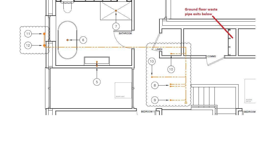
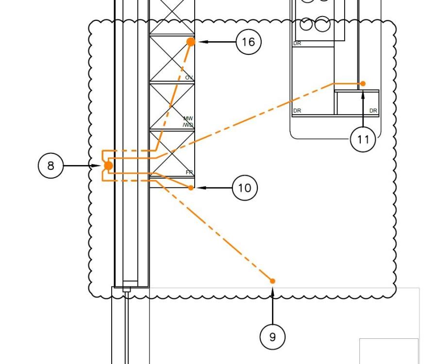
So, to round this off, here's the first floor plumbing into the same external SVP: All pipes into the SVP are from the first floor bathroom and run through the ceiling void above the kitchen that can be seen in the image. 16:WC 11: Shower 10: Bath 9: sink All fairly straightforward. The drawing appears to show, however, that each pipe penetrates the wall seperately to connect to the SVP externally, which seems bonkers to me. I assume this is just a drawing convention, and in reality the pipes will connect in the ceiling void for a single penetration through the wall to the SVP. Am I correct to expect the pipes to connect internally to give just one wall penetration? If so then should the diagram be amended to make this explicit to show a single penetration in the wall?
-
To answer your question properly..... ... roof is warm roof construction.
-
We did look at this and an internal SVP is more difficult here as it would need to run through the kitchen below. This pipe needs to vent outside as furthest from sewer, where the other soil pipe in the house vents internally to AAV. Also this side of the house is on the blind side next to the boundary and not visible from anywhere unless you go look for it. Thanks all for your input. It's good to know I wasn't imagining the proposed changes to the layout as being a bit, well, carp. Internally routed condensate drains it is then.
-

MVHR design questions
Mr Blobby replied to Mr Blobby's topic in Mechanical Ventilation with Heat Recovery (MVHR)
Thanks, pretty much my thoughts. Sorry, was typing at speed and not clear in my original post. There is a linen room and a seperate comms room, an extract in each. -
I started reading through the protocol documents and lost the will to live. I'll email my QS and ask him about goods from the South. He's paid to know about this stuff but my guess is he'll be as clueless as me. I'll report back if I get a reliable answer. Before Brexit, did self-builders reclaim VAT paid on goods bought from EU companies?
-
No to claiming VAT back in the normal way? What about main contractors in the North? Do they pay VAT on construction goods and services from companies from the South? I know that non-construction is zero-rated still on goods between limited companies over the border. I'll need to go and read those emails I've been getting from HMRC 😕
-
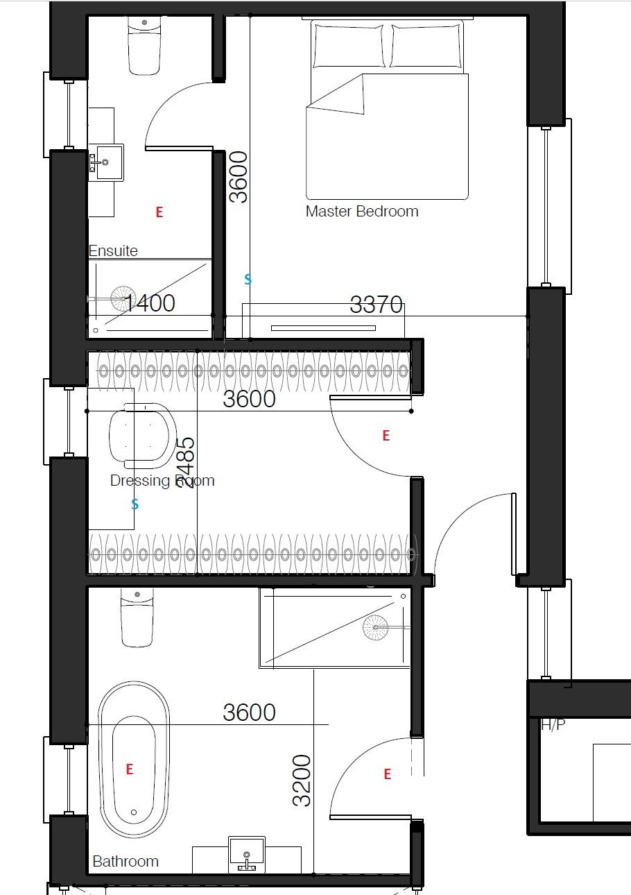
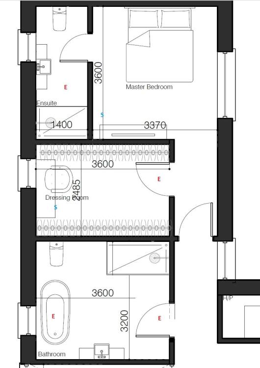
The proposed ventilation layout my designers have put forward is generally OK but I'm not so sure about the first floor bit around the bathrooms here: My concerns are: 1. The main bathroom has two extracts in line, which seems odd as the second extract will be 'behind' the first at the door. 2. The dressing room has a balanced loop, which is ok I guess, except my wife has never closed a door. Ever. 3. Why is the master bedroom supply duct not in the top right corner, away from the door? Is it bad practice to place vents above beds for noise reasons? All comments most welcome. Should I relocate the vents of concern to get a better airflow? (The remainder of this first floor has three more bedrooms, each with their own supply vent. And comms/linen with 2 extracts, so 5 supply, 6 extract in total)
-
Yes, I'm anticipating the same refusal, in which case can I claim the VAT back in the normal way? And, if VAT reclaim is the same as within the UK, then supply and fit is easier to claim the VAT back on?
-
I meant Irish Sea border of course 🙄
-
In the post-Brexit protocol world, where NI is sort of part of the EU with a North Sea border then how does self-build VAT exemtption work for goods and services from the South? If an Irish company (like KORE) supplies me goods, and charge VAT, do I claim it back in the normal way? If an Irish company provides installation services, should it be VAT free, like a UK builder would be expected to do? If an Irish company does supply and fit, then how does that work? 🤔😕
-
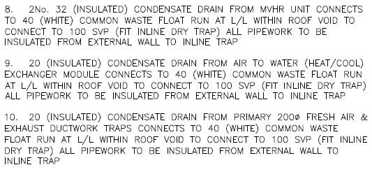
In the following diagram, 8,9 and 10 are condensate drains in the loft: The diagram suggests that these condensate drains should connect to a commonn 40mm pipe to exit the wall to connect to the external SVP at 12. On the ground floor where indicated there is a cloakroom waste that exits under the slab and a service void to the loft for the MVHR ducts. Would it be better to connect the condensate drains to a common pipe running down through the service void to the cloakroom waste below? That would save a penetration through the wall to the external SVP, which in a passive build I am trying to keep to a minimum. Is there a vertical drop limit for a condensate drain? Would the dripping of condensate be too noisy in the cloakroom below? Is running the condensate drain to the external SVP the best approach?

-
I've just noticed our M and E spec includes "automatic air vents to be installed at the highest point to discharge externally" in the same section as the heating/cooling flow and return that services the single MVHR heat exchanger in the loft. House is passive build hence I am trying to keep external penetrations to a minimum. Obviously I have limited knowledge about all this but am suprised to see automatic air vents discharching externally. What do the M and E consultants mean and do I need to vent externally?
-
Just for some background, the house is detached, no asbestos, service disconnected. Easy access. Stripped inside. Easy job, low risk. That's what I would have thought but one of the demo firms visiting the site offerred to give me a quote to do it directly. Interesting. I looked through the tender documents and couldn't find any detail on the demolition, which is odd. One of the demo guys who visited the site said the tender requires the harcore to be crushed and remain on site, which is news to me as I have no idea where they expect to put all that material. In the tender documents I have seen there is no demo spec that specifies hardcore crushed and retained. Odd. I must ask the QS if I have all the documents. And if not why not. The tender documents I do have do highlight concerns over cables running over the corner of the site. This was queried by demo contractors onsite because, FFS, I had openreach insall a new pole and transfer those cables over a year ago and told my architect at the time. 🙄 Whatever the QS has put in the tender for the demo, it looks like its wrong and the QS, for whatever reason, doesn't want me to see it.
-
Is there a curing time for KORE insulated slab before laying masonry blocks on it? How long, roughly, should I insert into the plan for this curing time?
-
My QS wants the demolition of the existing dwelling on my site to form part of the tender going out to the main contractor. I want to be buildng this summer so would like to save time by getting a demo firm in directly before the tender responses come back. Any main contractor is only going to go to the same demo firm to get the same job done (I know because demo firms have come to site to quote MCs) so why wait for the same job to be done and probably pay a slice to the main contractor for appointing the demo firm? I can't see any down side in getting the site cleared in June and take the demo outside of the main contract. My QS is strongly advising against. Why? What's the downside of clearing the site now? AM I missing something?
-
.. I meant of course zone of influence 🙃 ... and how wet does the cement slurry need to be?
-
So can I put more than 1 rod through the bottom of the "kiosk" or do I need to worry about the 'sphere of influence' and space then out?
-
After panicking for a day my brain finally engaged I did just that and put a conduit to come out under the slab to install another rod under a seperate pit if needed. It's obvious now of course. Yes, this is my understanding, and just as well given my state of preparedness. Hopefully I can get the barby built by thursday. That's when NIE are scheduled to pull the cable through, and when hopefully I can breathe a sigh of relief. .. and thanks for the pics inside your 'kiosk'. NIE rules are harsh for commando sockets and brick barbies.
-
I didn't really think this through 🤔 My temp installation is on rocky ground and no way can I get an earth rod in. The whole site is pretty rocky so relocating the enclosure is not really an option. Short of getting the digger back in to break the ground up, is there another solution here to get an earth rod into stony ground?
-
I assume you chased yours into the wall? My meter is on "hidden" side of the house so looks not too important
-
Can I do any of this? Can I embed the hatch into concrete and the spark put the earth rod in later? Or not?
-
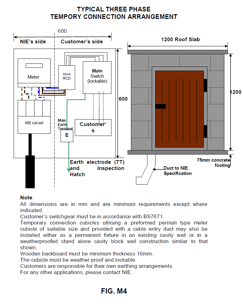
Ah, so I shoudn't put the rod in the ground then? But I can place the hatch in postion so that I can pour the slab. And get the spark round later. As I understand it, the earth is "my side" of the NIE temp enclosure: ... so the sparky-earth rod job does not need to be done before NIE pull the cable through? I can just put the hatch in the footing and get the sparky out later?

-
I get the feeling I'm not allowed to do this then. Can I install the hatch into the slab and pour my concrete and then get the sparky to put the rod in?
-
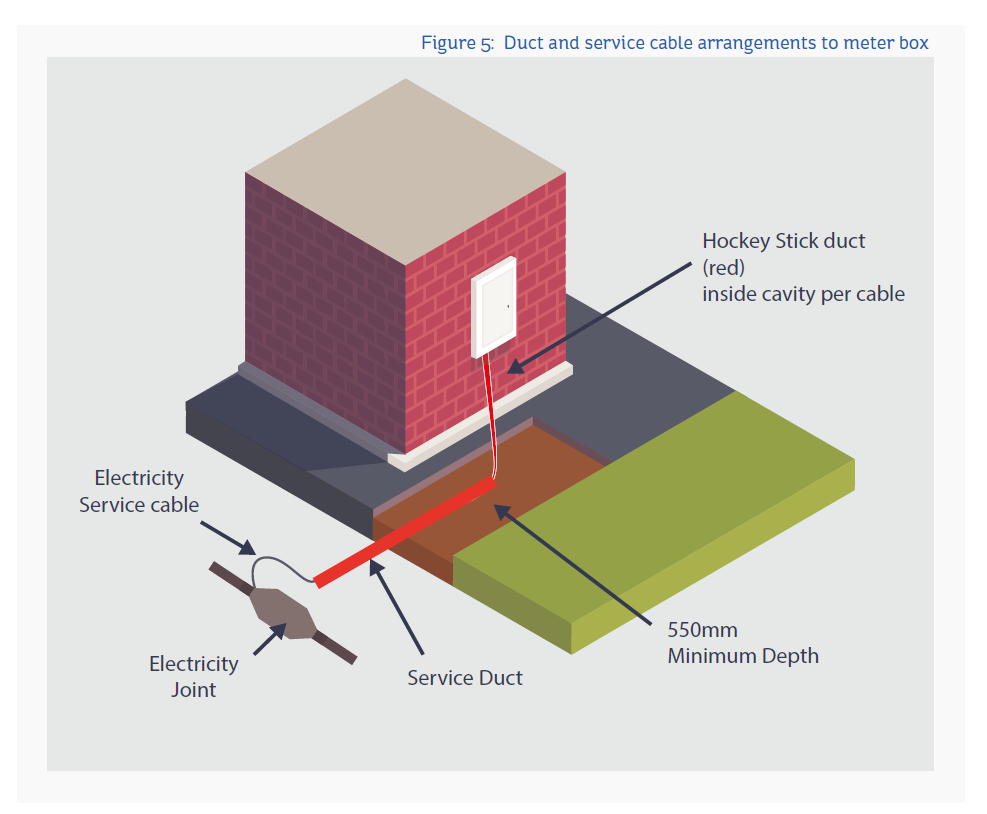
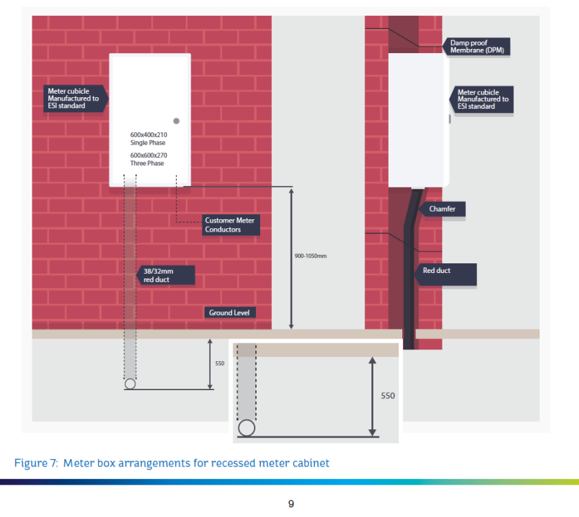
I know, it seems bonkers. My M and E people have specified the supply cable to run up inside the cavity into a recessed box. Here's the NIE directions: NIE allow for a surface mounted meter box where it is not possible to run the cable inside the cavity. Should I push for a surface mounted box with external cable run up the walls inside the protective conduit?

-
I need to build an earth inspection hatch into the concrete base of my temporary supply. What is it? Which one should I buy? How do I install it?