


Gus Potter
-
Posts
2207 -
Joined
-
Last visited
-
Days Won
26
Everything posted by Gus Potter
-
Drainage lintel strength and bearing
Gus Potter replied to MortarThePoint's topic in RSJs, Lintels & Steelwork
I would give them a quick call just to check. -
Drainage lintel strength and bearing
Gus Potter replied to MortarThePoint's topic in RSJs, Lintels & Steelwork
I think the Naylor P215 lintel is still only 65mm deep. I would run it by your Engineer just to be sure. It should just be a quick phone call. All the best. -
Drainage lintel strength and bearing
Gus Potter replied to MortarThePoint's topic in RSJs, Lintels & Steelwork
Hope this helps. Lintel sizing. Engineering units an explanation and how to get a rough gut feel for how heavy / how much load a simple wall for example imposes or a beam / lintel. Keeping it simple if you weigh 15 stones this is roughly 100 kilograms. An old Volvo was commonly referred to (reputably) as weighing 1 Tonne = 1000 kg. You may wish to take this as an Imperial Ton but let’s not split hairs! UK Engineers tend to work in units of load called Newtons (N). Often seen in structural calculations is the abbreviation kN = kilo Newtons thus 1 kN = 1000 Newtons (N). To convert kilograms to Newtons you multiply kg by gravitational acceleration which can be rounded for most practical purposes to 9.81m/s^2 (metres per second squared) when producing the calculations. To get a feel for things just say this is 10 m/s^2. Now 100 kg x 10 m/s^2 = 1000 Newtons (N) = 1.0 kN. If you weigh 15 stones in Engineering parlance the load on the ground when you are standing still is ~ 1.0 kN. An old Volvo weighs about 10.0 kN ~ a tonne. What about the lintel? Dense concrete block wall (block compressive strength 7.0 N/mm^2) weighs round about about 20 kN/ cubic metre (density) including the mortar to stick it together, (ref: Structural Engineers Pocket Book. F. Cobb). If you have a wall 3.0m high you have a load per metre run of wall of 20 (density) x 0.1(thickness) x 3.0(height) = 6.0 kN/m ~ 600 kg per metre run of wall. You often see this referred to in calculations as a “UDL”, a uniformly distributed load. Key Point! The load calculated above is a “working load” per metre run of wall (kN/m) also called an unfactored load. This calculated load has to be less than the “safe working load (SWL)” declared by the manufacturer. Some manufactures give tables based on a “total safe working load” or “total permissible load” thus if you have a lintel of 1.2m long the total load is 1.2m x 6.0 kN/m = 7.2 kN Some give information based on a safe working load per metre run of lintel (kN/m). Look carefully! You’ll also see data tables that refer to a “characteristic load” Please do not confuse the two as the SWL / permissible load tables have some (but not all) safety factors built into them. Characteristic loads do not. These loads have a higher value so are not safe to use without safety factors. You still need to make sure the rest is adequate and anything below and to the side. Not all lintels are the same! For pre stressed concrete domestic type lintels there are generally two common types. One is called a “composite lintel” the other a “non composite lintel. A composite lintel works mostly by creating a triangulated “A” frame where the masonry above acts in combination with the steel rod in the lintel which is in tension with the masonry above acting in compression. Essentially, you create a deep composite beam to span the opening. To make this work you need a good few courses of continuous masonry above it, a bit either side too and generally no concentrated loads directly above. This is usually qualified in the manufactures tables. However, if you have say an offset opening above the lintel which introduces concentrated load or some floor joists perhaps that bear on or near the top of the lintel then you can lose the effect of the composite action. You need then to perhaps consider a non composite lintel. I have copied a screen shot from Robeslee data table below for a flavour. For a clear span (structural opening, not to be confused with an effective span... best for another day) with 5 layers of brickwork above and assuming correct and adequate lintel rest at the ends, the lintel will support a UDL (distributed load) of 30 kN/ m run. This looks promising when we look back at a 3.0m wall leaf loading of 6.0 kN/m run. If you have the wall width you possibly can use two side by side and introduce a header course or two of brick to tie them together along their length. But “without brickwork” to create the “A” frame / composite action” it drops massively to 3.86 kN/m which is ~ 380 kg /m and that is roughly a ninth of the allowable permissible full composite load Now you have overloaded the lintel by a serious amount when we compare this to the load from a 3.0m wall leaf. However it looks like you are using blockwork not brick. When used to support blockwork the composite strength of these lintels can be a good bit less than when used with brickwork so check with the manufacturer. Much also depends on where you put the DPC. Clearly if you are opting for the composite route and you have a slippy piece of DPC inserted in the bricks that are acting compositly it stops working. Practically you may just want to go for a non composite lintel in case you want to knock a hole in the wall later on! In summary. Look up, see what is above and what you need to hold up and just as importantly how stop anything moving sideways (lateral restraint) or twisting (torsion). Remember that the inner and outer leaf of a wall could be carrying different amounts of load. Also remember that it is important to look down too and see what you have below as a support. There is a saying “if it doesn’t look or feel right it probably isn’t”! If you have any doubts at all it’s always best to ask the structural designer which you may want to do once you have had another look.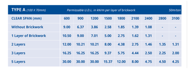
-
Overkill spec on reinforcement- suspended slab, basement wall
Gus Potter replied to Tony C's topic in Foundations
Hope this helps, a bit lengthy but... You maybe can use mesh but if you want to achieve the same equivalent bar area to 12mm diameter H12 bars then you may need to look at the B type structural meshes, perhaps a B785 mesh? The rub here is that the bars are different sizes in each direction with different spacing. Has the slab (maybe basement walls too) been designed as a two way spanning slab. Roughly meaning that all the edges of slab are fully supported all round so that the main reinforcement bars act in two directions perpendicular to each. If so, then you may need four layers of mesh (2 top + 2 bottom) as opposed to your 12mm diameter H12 loose bars top and bottom as the secondary bars in the mesh may be too small. Although mesh can be great you can have a problem with “nesting” if using lots of layers. Were four sheets come together it’s difficult to lap them properly and keep the concrete “cover” to the reinforcement. You can get a flying end mesh but on a small project this can add to the cost, difficulty in sourcing and you may need to detail it up so it fits. Also think about how you reinforce the corners of the basement walls as you can get congestion here too. Although mesh can be appealing if you have congested reinforcement it’s harder to compact the concrete properly and that can cause problems later on. Perhaps have a look again at using loose bars. An H12 is not a bad bar, not too floppy and not too heavy. They come in various stock lengths, easy to source and price match. Also, if you run out you can nip to the stock holder and grab a few more. Any off cuts are great for garden stakes or using as dowels etc. Once you get going with tying loose bars you’ll get along fine I’m sure. If you make a small mistake then all you need to do is remove the odd bar or two rather than sheets of mesh that you may have cut. Just remember that when rebar is tied together it is very heavy so make sure it is properly braced and shuttering is supported. Clay soil (say when you have cut down a tree) can exert a significant load on the walls of a basement. The soil can take a number of years to readjust to the new ground water conditions. There are a good few ways of designing concrete basements / floor slabs. When you don’t have other buildings /sewers etc close by then broadly some key areas considered are; strength (so it does not collapse), deflection (so it does not bend too much and damage other parts of the structure) cracking (to control water ingress and again damage to other components and finishes) and buoyancy / drainage... it’s not a boat so you don’t want it to float if the ground water rises. When a floor slab is say simply supported at each end only and it is loaded from above you will get tension in the bottom of the slab. Steel is good for resisting tension hence your main bottom steel. If you have a load bearing internal wall in the basement then you have a two span beam. You still get tension in the bottom of the slab as you approach the middle of each of the two spans. However, you usually get tension in the top of the slab over the internal wall. Hence your main top steel. It may be that the basement has been designed as a continuous box. In effect the concrete and reinforcement work together at the corners (often called a moment connection) as opposed to say the basement floor and walls acting together with the suspended slab only designed to prevent the basement wall heads moving inwards and to carry the loads from above this is more of what is called a pinned connection. If this is the case then you also have tension in the top of the suspended slab and the outside of the vertical basement wall at and near this junction thus you need some steel in the top and outside of the vertical walls and this can be a congested area. You can ask the Engineer how the design works, often they are more than happy to explain. It’s worthwhile to know how something stands up, especially when you are finished the project and enjoying the fruits of you labour in front of the fire on a windy winters night.

