


JohnMo
-
Posts
13308 -
Joined
-
Last visited
-
Days Won
200
Everything posted by JohnMo
-

Mini Store - Heat Geek / Newark Cylinders for ASHP
JohnMo replied to Nick Laslett's topic in Air Source Heat Pumps (ASHP)
Correct. The volume of water in the cylinder of the HG arrangement is treated as part of the heating system with expansion and relief provided at the heat pump end. As long as the return leg from this cylinder is always in the flow path to the heat pump all is good. But if your heating system volume is 100L, and expansion sized for that, you would have to increase the expansion vessel so it's sized for 150L and the appropriate upper temperature limit of the cylinder. -
MVHR specification?
JohnMo replied to Philxyz's topic in Mechanical Ventilation with Heat Recovery (MVHR)
I would look at 90mm also. Found it worked out way cheaper, as all runs became single ducts, for our house which is long and thin. With 75mm most would have ended double 75mm ducts to each terminal. -
MVHR specification?
JohnMo replied to Philxyz's topic in Mechanical Ventilation with Heat Recovery (MVHR)
You don't need to get down to that detail, just get pressure drop data from the chosen manufacturer and they will list pressure drops for duct and fittings. You just need to do the most onerous route for a semi flex manifold system, you then add the plenum and the duct between MVHR and plenum to get the complete pressure drop. Get that as low as practical. -
MVHR specification?
JohnMo replied to Philxyz's topic in Mechanical Ventilation with Heat Recovery (MVHR)
You need to work out how the air will move around the house, so if air enters room A, B and C, where does it travel to get to the extract terminals, you are aiming to have air wash through the whole house. Plenty of good practical advice in the attached. 2018 MVHR Good Practice Guide rev 1.1.pdf -
So I get notifications start by typing"@" then the user name from the drop down that appears. You only need a single coil. I use a cool energy diverter, this has a timer that allows to time immersion running or you can just leave it in diverter mode. So your plumber is talking rubbish, a double coil is for solar thermal, not for PV diversion. Above all else get a heat pump cylinder with as big coil as you can get, with X plan (or Priority demand hot water).
-
MVHR specification?
JohnMo replied to Philxyz's topic in Mechanical Ventilation with Heat Recovery (MVHR)
Seems a bit of a strange way to do duct runs. Looks way too many ducts. That's not right, you need to calculate duct length and pressure drop. Your kitchen needs extract, but your living area is very likely going to need supply. Use this to help decide the room flow rates required.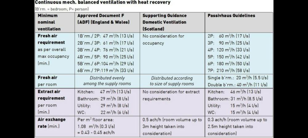
-
No issues doing that as far as I know. Everything I have seen on the MCS heat loss calcs they are over egged generally.
-
Mini Store - Heat Geek / Newark Cylinders for ASHP
JohnMo replied to Nick Laslett's topic in Air Source Heat Pumps (ASHP)
Correct, the superflow temporal store required an additional 5 lt expansion if system volume exceeded x lt. -
To give a quick example, flowing at 55 at -2 compared to day 35 at -2 would use around 40% extra electric. System design is the be all and end all of heat pump efficiency. It's super easy to accept a rubbish system then have an uncomfortable house, that's too expensive to heat.
-
Mini Store - Heat Geek / Newark Cylinders for ASHP
JohnMo replied to Nick Laslett's topic in Air Source Heat Pumps (ASHP)
Seemed to do fine, didn't seem to have any shortage of hot water. Hot water heater takes about 40 mins at the end of it the condenser is frosty. -
Mini Store - Heat Geek / Newark Cylinders for ASHP
JohnMo replied to Nick Laslett's topic in Air Source Heat Pumps (ASHP)
No stored volume of domestic water is below the need for G3. It's a buffer cylinder really with a DHW coil, not really a thermal store. Exactly as I listed in the image above. Defrosts could be a issue, but my heat pump specifically doesn't defrost, during DHW - it's not allowed by the manufacturer control logic. -
Hot water cylinder as buffer tank
JohnMo replied to Little Clanger's topic in Central Heating (Radiators)
That would work, I would use around 50mm as a minimum. Insulation on pipes 25mm. -
Is there a reason you have to go via the council? And not direct to installer and they would claim the grant via normal channels.
-
Mini Store - Heat Geek / Newark Cylinders for ASHP
JohnMo replied to Nick Laslett's topic in Air Source Heat Pumps (ASHP)
Just watched the follow up video. Looks good, seems to work well. It is as shown in my post above. The heat pump heats the store directly and DHW is taken via a coil. The blending valve would be installed if you store water above 60 degs. -
Ignore heat pump size for now. The system design flow temp needs to be as low as practical. At the end if the day you are the client, not the government or anyone else. The government is funding YOU via an approved supplier installer. I would be pushing for a max flow temp of 35 to 40 @ -3. Anything else is just asking for high running cost. Other suppliers out there. Just tell them NO to current design. Tell them to fix it or you will find another supplier.
-
If architect will not or can't explain why, find an architect who you can work with. The architect should be able to produce a U value and interstitial condensation report quite easily, to show you the issues (if there are any). Another option is full fill poly beads, which give a self draining cavity
-
Tech specs look good. You may be surprised by the price, but sure in a good or bad way. Looking at the specs, they quote the U value for the glazing unit only, not the window. So depending on frame that figure could be better or worse. I would choose your frame, then tell them to quote with the vacuum glazing. All companies buy in glazing units. Or get a quote direct yourself https://fineo-vacuum-glazing.co.uk/new-vig-technology-for-older-properties/?gad_source=1&gclid=CjwKCAjwmrqzBhAoEiwAXVpgopshC3r1JHPktll0X4iUmu7osYDF58q_w4fDppojtzb4AGXkxC9xCxoCggkQAvD_BwE Another alternative is krypton filled which is better than argon filled.
-
A man in a digger way easier. A day or so all done, the digger would pull everything out the ground at the same time.
-
Bigger plug? So it's a tight fit.
-
That would work. Good thinking.
-
Mini Store - Heat Geek / Newark Cylinders for ASHP
JohnMo replied to Nick Laslett's topic in Air Source Heat Pumps (ASHP)
A similar concept been about for years (since 2018 ish) - funny it for a gas combi boiler. Just swop the combi boiler for a heat pump with a bigger coil and delete the blending valve and go direct to taps (not to the combi). Same 4 connection. Neither a vented or invented DHW cylinder, just allows for additional volume with an additional or increased heating expansion vessel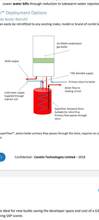
-
Bingo - not The 35mm refers to the depth of the box, the issue is the 35mm box is good for up to 16mm wall thickness you are wanting nearer to 25mm (with plaster), so then you need the deeper 47mm back box, but not all of them are suitable either
-
Mini Store - Heat Geek / Newark Cylinders for ASHP
JohnMo replied to Nick Laslett's topic in Air Source Heat Pumps (ASHP)
Must be being treated as heating system volume, so must be full of central heating water, so the volume of main fed water is limited, contained in a coil or PHE as with a thermal store. -
Mini Store - Heat Geek / Newark Cylinders for ASHP
JohnMo replied to Nick Laslett's topic in Air Source Heat Pumps (ASHP)
Good point. I have seen schemes where DHW is delivered via a PHE, such as a thermal store. The HG solution is really just adding a buffer to the system to allow the ASHP to ramp up. Mine would take a good 5 to 10 minutes. So it could be a coil in a coil HE within a buffer tank. The outer coil is in the buffer water the inner coil in the ASHP flow path. So are they just treating the store as a buffer from a plumbing perspective. -
Mini Store - Heat Geek / Newark Cylinders for ASHP
JohnMo replied to Nick Laslett's topic in Air Source Heat Pumps (ASHP)
I noticed a while ago in my ASHP instructions, there are settings for that type of operation. " In Heating, ASHP always turned towards DHW" 10.2.2 HEATING MODE ON DHW STORAGE TANK If the parameter H130=1, the ASHP exploits the DHW storage tank even for central heating. In these conditions, the outlet of the DHW valve is also enabled during operation in heating mode and not only in sanitary mode. The valve is deactivated during defrosting and in cooling mode. Think you would have to alter the plumbing to allow it to work. A a 3 port valve directs towards CH or cylinder not both.




