Tony L
-
Posts
397 -
Joined
-
Last visited
Everything posted by Tony L
-

Yeeessss we bloody done it.
Tony L replied to Russell griffiths's topic in General Self Build & DIY Discussion
Well done, Russel. That looks fabulous. I hadn't realised you weren't already in. -
This has got me thinking: due to planning constraints I've ended up with a messy roof design - I can likely go for wide gaps between the sarking boards on the sections that will likely never be walked on, & this will give a worthwhile saving, but I'm guessing my standing seam will be going on before I get onto cladding the dormer faces & cheeks, so I'll need the adjacent roof sections to be more robust.
-
Russell's 100 x 25 is probably a better suggestion than my 150 x 25 - assuming there's negligible increase in flex. The 100s likely save more in materials than they cost in additional labour. Furthermore, I can see that fitting these is a job that I'd enjoy doing myself, so it doesn't matter too much if they're going to take an extra day.
- 19 replies
-
- 1
-

-
- vapour control layer
- standing seam
- (and 9 more)
-
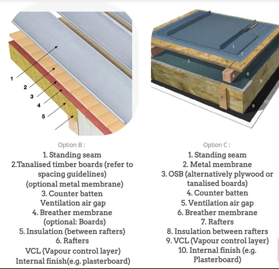
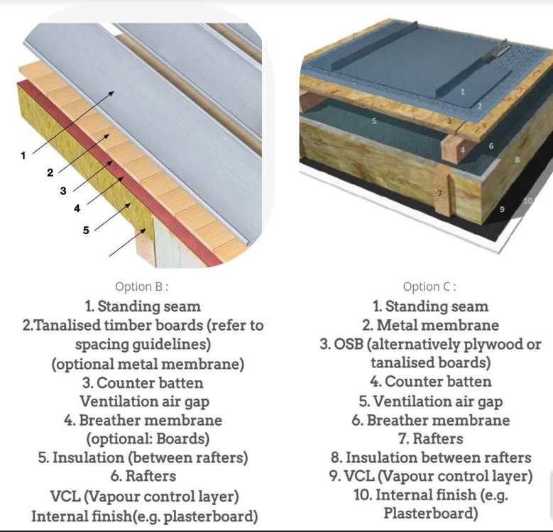
That's good to know. This is something like what I have in mind for my build (left side image). What this drawing doesn't show clearly is, there's an air gap above the red membrane (4). The air gap starts at the gutter & goes all the way up to the vented ridge. Also, I'll leave gaps in between my 150 x 25s - the gaps will be as big as I think I can get away with & still be able to walk on the roof without any risk of damage; the bigger the gap between each board, the cheaper the roof.
-
@SimonD didn't suggest woodfibre. My understanding is, woodfibre sarking boards are used when extra insulation is required, & they're likely held down onto rafters with softwood battens, so their sub-optimal pull out qualities aren't a concern. If you already have a ton of Kooltherm on your roof, as your drawings show, you don't need to worry about another few mm of insulation. I think @Russell griffiths is suggesting 150mm x 25mm treated softwood planks. These don't fully cover the roof - I've seen them installed with 10mm or more gaps between each plank, so they support the standing seam & the gaps assist in drying, should the wood become damp. I'm no expert, so listen to others' views, but I'd want some ventilation under the standing seam. I'll try to find a picture... Of course, the problem with the treated softwood 150 x 25mm is, the materials cost is going to be more than OSB (or even 22mm ply) & they're going to take a lot longer to install, as well. I haven't done the maths yet - I need to, because this is exactly what I'm planning to do for my roof.
- 19 replies
-
- 2
-
-
- vapour control layer
- standing seam
- (and 9 more)
-
Thank you very much @Gus Potter & @Iceverge for your recent posts. I have so much to do before I go away, I'm going to have to leave this now, & pick it up again the week after next.
-
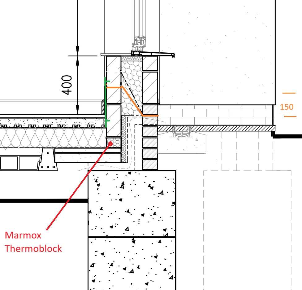
The orange 150, above, is supposed to represent the height difference across the orange tray. I've just realised the top bar is drawn a little low, & my 2 minutes, or whatever is allowed, of editing time has expired.
-
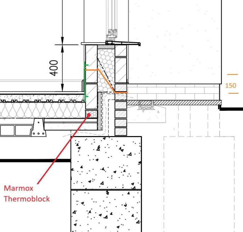
I thought I'd put up a clearer picture of the poor detail @Gus Potter pointed out so that anybody who's interested can see it clearly. I'm wondering if the cavity tray went in under a full block (see orange line), this would make the arrangement sufficiently robust. We could also attach some steel brackets under the window (green line), with bolts into resin & appropriate attention to air tightness detail, behind the brackets. I've only just come up with this idea. No doubt there will be a proper way to do it, which will work better & cost less - please advise. The cill projection, at about 100mm, looks vulnerable & is much wider than I want. I've asked for this to be reduced to 45mm.
-
Thanks very much for pointing out this error - I hadn't spotted that one. Although, I don't understand which bits are, "the shaped insulation". I'd expected the air brick periscopes would be drawn, hard up against the outer leaf, & I'd have more EPS beads under the cavity tray & between the periscope & inner leaf, right down to the trench blocks. As it is, there's a gap on one side of the periscope & some unspecified board on the other side. The brick sized cross section at the bottom of the inner leaf, on top of the block & beam, is a Marmox Thermoblock. Yes, it does. Thank you. Yes, it's hard for me to learn, especially with the house build being just one of several significant responsibilities I must devote time to. I am keen to learn all about this, but when I began this project, I didn't imagine I'd be forced to learn in so much detail, to mitigate the losses from people who want to rip me off & others who are just incompetent. I have already been thinking, with his limited talent, this arch tec’ is only going to be able to get us so far & unless I start again with somebody else (4th re-start) with the drawings, I’m going to need to pay somebody who knows what they’re doing to go through everything the current arch tec’ draws & re-work the details he’s not able to design properly. I know I can’t trust my arch tec’s work, because, even with my very limited understanding of what needs to be done, I can spot many errors & I can see he doesn’t fully understand how to do his job properly. Even if I start again with somebody else, there’s no guarantee the next person would be any better. I came across Richard Bendy, who may be the right person to check over the drawings. I haven’t made contact yet: https://www.thehealthyhome.uk Ideally, my arch tec’ would pay Richard to show him where he’s gone wrong, & teach him how to do what I’ve contracted him to do, but I know this won't happen. Richard Bendy's services include training architects. Re. paying professionals: I had a good meeting with a proper architect, who has designed & overseen the completion of some certified passive houses. His quote (& this is for a house that has already been designed to PP level & for which PP has been granted) was £28,272 inc VAT. This included 12 hours for electrical layouts, which my current AT’s contract doesn’t specify, & some of the things that my AT has so far failed to include in his drawings, such as door threshold detail & intermediate floor to external wall detail, were specified in the £28k+ quote. There was also a substantial fee for, “building contract admin, PD & on-site support”, which I negotiated down from the quoted fee to £2,160/month (inc VAT) for the duration of the project. I was told that it would be very unusual to proceed without this monthly fee, but if I chose to do so, I’d be completely on my own once the drawings had been handed over & I wouldn’t be able to call for help with the build (a condition arising from the architect’s insurance policies). So that’s £50k, assuming we pay the monthly fee for 10 months & don’t need any extra drawings. & this fee was based on me providing the .dwg format drawings (which I had only as .pdf) from the AT that I was about to sack, for being quite a lot worse than the current one. A prominent member on here explained, many architects overcharge for work that’s often sub-standard. He highly recommended the AT I‘m trying to work with now. This BH member gives out good advice here on BH all the time & I trusted his judgement. Here’s an excerpt from the current AT’s quote: My fee to prepare a detailed set of construction drawings for a dwelling of this scale and design, including detailed floor plans, 2 x sections, annotated elevations, site plan showing drainage and services, specific details of key elements which require further thought/ironing out such as the cantilevered box and corner glazing and a set of construction notes/specification, would be £6000 plus VAT, 50% of which would be payable upon instruction with the balance payable upon issue of final drawings. This is an all inclusive fee for the complete set of drawings and details. There are no further charges for any amendments required or liaison with structural engineers or building control, or indeed yourself. Therefore there are no nasty surprises further down the line. Thanks again, Gus. I’m away from Friday, for 9 days, so I must just explain: any comment anybody posts will be gratefully received, although I won’t respond until the week after next, because I’ll be having a fantastic time snowboarding & screen time will be limited to essential work comms only.
-
Sorry - my fault. I should have quoted or namechecked you when I posted, so you'd have receive a notification.
-
I might be persuaded to use something other than block cavity walls, but I’m under pressure to get my notes on how to fix the draft drawings back to the arch tec’ – under pressure from both the arch tec’ (I can put him in his place if I need to) & from my partner, who’s paying for half of all this & has become very frustrated that we’re not already much, much further forward with this project; I feel that if I take a step backwards & demand more extra time from her, for a complete structural redesign, this may lead to severe consequences. I’m also keen to get these drawings finalised soon, so we can get a BoQ/build cost, & following this, if my partner isn’t prepared to commit to spend half of whatever it might take to build this design, we’ll need a re-think. Building costs are very much higher than when this project was conceived & house values are not that much higher. I chose cavity walls because, I was told (a long time ago now) this would be the easiest & cheapest way to build. This project has been going for many years. It took forever to get PP. I designed the house before I discovered BH. The PP design has 100mm cavity walls & pre-dates the building regs change to 150mm. Obviously, my latest design has a 150mm cavity. I’ve attached the approved drawings. Since these were approved, I have persuaded my partner she really does not want a wood burner, & I’ve deleted the chimney & some of the windows. To save money & build complexity, the arch tec’ deleted the 550mm (F to C) loft space in the dormers & reduced the height of the dormers. I’ve moved some of the walls around inside, to give more space to some rooms & take it away from others; for example, there’s now more space for MVHR & other plant room gubbins (all on the left of the back door as you walk in) & less space in the adjacent room (snug). I’ve attached the approved plans. These are really poorly drawn (by me), because I had somebody helping me with construction notes, etc, back when I didn’t understand this so well; he was supposed to re-draw my rough design, but he said my drawings were good enough to use for a planning application, & we just needed to add a scale bar & a few notes. Also, I'll just mention, the construction drawings show a chunky (215mm blocks laid flat) wall next to the stairs, so I can have a floating staircase for the top flight. That's if there's any money left when we get to that stage. All the block inner walls are spec'd to go onto Marmox Thermoblocks. TonyL_NMA-ELEVATIONS.pdf TonyL_NMA-FLOOR_PLANS.pdf TonyL_ROOF_PLAN__SECTION.pdf
-
Can you not use slabs? Thanks for the suggestion, Nick. Yes, I could do, but I like EPS beads because: EPS will fit perfectly into all the awkward shaped edges, on top of cavity trays, into a badly built section of cavity that is 165mm wide (ref: one of my threads from months ago). If my trench blocks get wet, I think wet/damp EPS will be better than wet/damp mineral wool. It doesn’t have to be stored on site. It won’t get wet during installation. It won’t be installed by the brickie, who’s on a price for the job & who’s motivated to work quickly & cut corners (ie leave gaps in the insulation), so he earns himself a paid day off at the end of the job. We’ll be able to start putting the roof on sooner. Perhaps the brickie/brickies will enjoy laying the blocks & do a better job if they don’t have to faff around with fluff. The internet says EPS will be cheaper (so I’m assuming, if it costs more it won’t be loads more). The internet says EPS has a better R-value (& that will be as compared to the expertly & patiently prepared mineral wool that was lab tested to deduce its R-value). I reckon I can procure EPS installation service myself, so I won’t have to rely on the builder to deal with it, nor pay him to watch it being done, nor pay his margin. I get to choose who does the work & it will be easier for me to arrange to be there to oversee it when it happens @Iceverge likes EPS & I’m an @Iceverge superfan.
- 77 replies
-
- 1
-
-
- flat roof
- condensation
- (and 2 more)
-
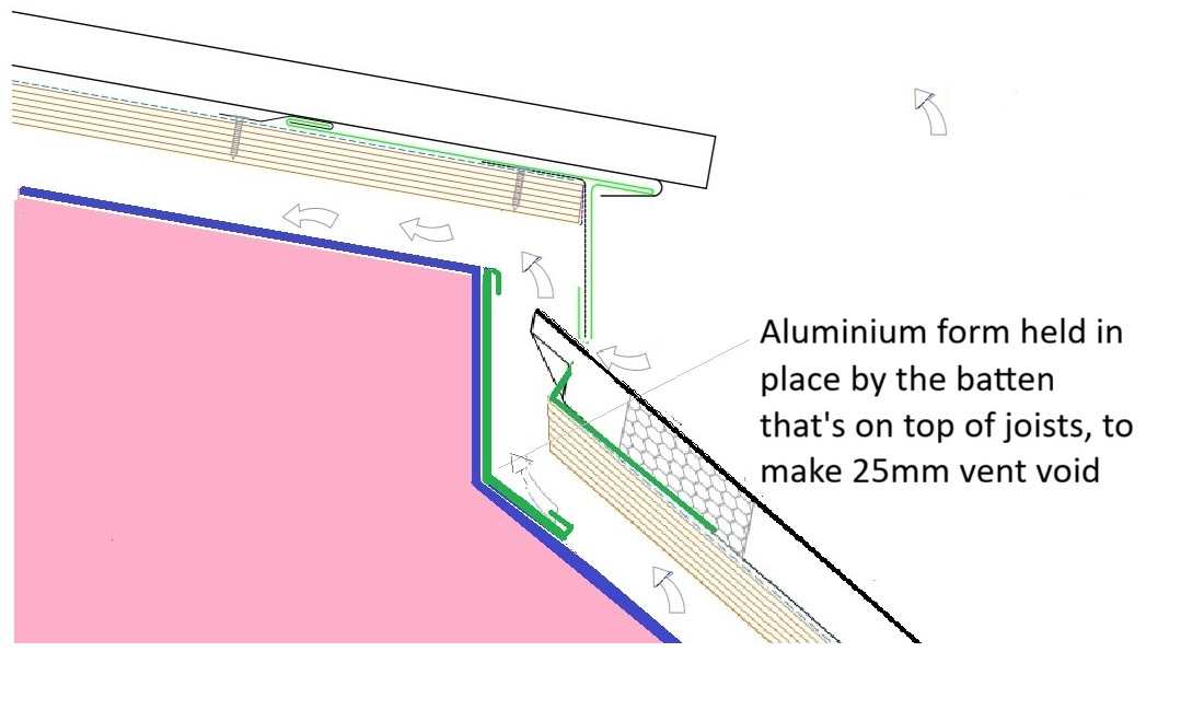
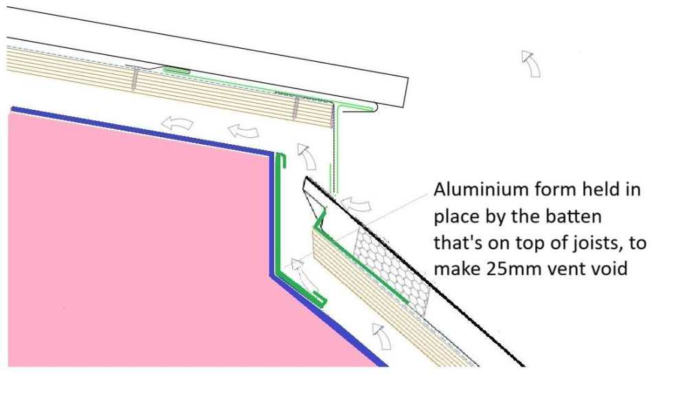
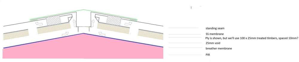
& here’s a detail for where the 3 degrees centre section meets the 42 degrees section. I’ve added in some L shaped plates (green) to prevent rain being blown up the roof & into the vent void. This same detail could be used where the the 42 degrees sections meet the backs of the 3 degrees flat roof sections over the dormers.
-
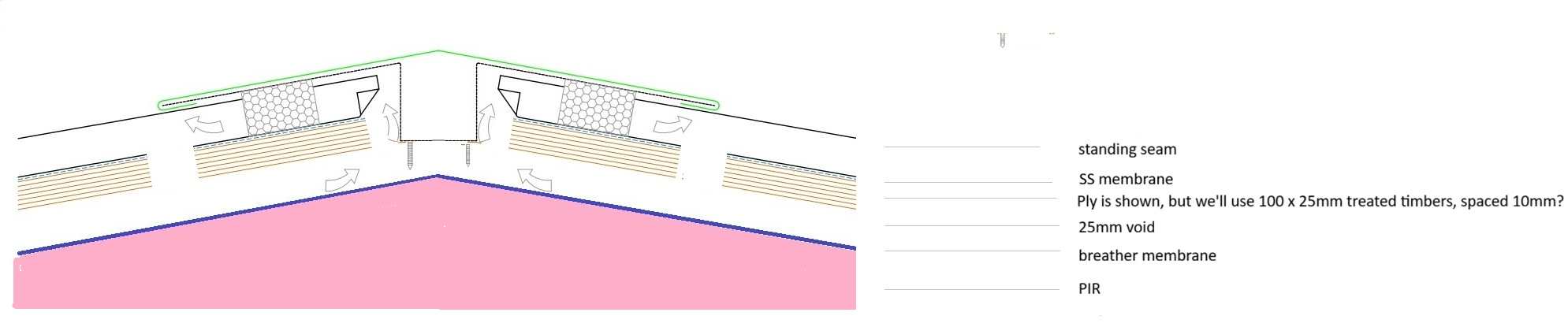
I’ve added to a drawing I found online to show how the ventilation & drip edges will work at the apex of a standing seam roof, at 3 degrees .
-
I’m sorry to make the task of resolving these problems more difficult but, there is no way I’m going back for a new planning permission. I don’t want to spend time explaining the long history of how I eventually achieved PP for something that I actually wanted to build: I need to focus on what’s ahead. That's not far off what happened, yes. I don't know anything about site poured lintels. I think I ought to minimise the number of technologies I must learn about to get this house built - I'd really want to learn about it because I wouldn't trust a builder to do it properly, if he thought I didn't understand the process. My learnings about works up to DPC (mostly from BH) saved me at least £7,000 after the builder took advantage of BC's requests for changes & tried to rip me off. I like glulams too. Are these OK to stick through the inner block leaf, so they're flush with the cavity (wrapped in VCL, of course)? Sorry, I can't visualise this. Are you talking about the long inner walls that the rafter ends sit on or the gable end walls (that will have ladders going over them, for some roof overhang)?
-
Thanks again for this, @Iceverge. I like what you’ve drawn. Sorry, the roof can’t be at 45 degrees because this would stretch the flat roof section at the top & make the building look very different from the approved plans. 400mm EPS in the walls is appealing, but it would make the inside too small & it can’t happen because [I’ll be in big trouble with you when you read this] the substructure is already built. For the benefit of anybody reading this whilst researching your possible self build, & to save @Gus Potter & @Iceverge the trouble, l will just explain: building the substructure before your superstructure drawings have been finalised is a very bad idea.
-
@Iceverge. Thank you again for your work on this. I'm pleased you support the idea of "flat roofs" being standing seam at 3 degrees. Let's hope the planners consider this a reasonable fall for my approved flat roof sections (I'm not intending to ask them). I've been working on some detail drawings for the roof intersections this morning. I have to go out now, so I'll aim to I'll finish these off & post them this evening, along with responses to the other points from your post above.
-
Thanks for all this, @Gus Potter. I've designed all my metal web floor joists so they're inside the inner block leaf; those that meet the outer wall will be hung on ledger boards. I've done this to make air tightness easier to achieve, & there's a thermal break benefit too. With the ideas @Iceverge has provided, the tops of the rafters will all be insulated, but at the bottom they'll run from inside to outside over the wall plate, of course. The SE has specified UB19 for the beam in the section picture you posted. This is a fair bit chunkier than I was expecting - only because I can lift the mild steel box section back bone chassis of an old Lotus with ease, & they're very strong. These UB19s (there are 6 of them) are in lengths of max. 4.55m, so that's 86KG to lift into place. I think the top of a UB19 will be 7.9mm thick & the web will be 4.8mm, so it will be good to have insulation along the edges of these UBs, & it's worth considering what's going on at the beam ends too. My plan was to wrap the beam ends that penetrate the inner cavity block leaf with VCL membrane, bring the membrane inside & fix it to the wall (I've got notes on how to affix). The cavity between the block inner & rendered block outer leaf is only 150mm & will be filled with EPS beads. I was thinking it may be worth sticking a rectangle of super insulating something or other inside the cavity on the beam ends. If anyone has any suggestions please let me know. & is it worth sticking a block of high R-value something on the top flanges? There's not much gable end wall going on top of these UB ends. I looked for high R-value padstones, but I gave up this search & decided to rest the beam ends on regular padstones.
-
Stairs have more headroom than building regs require - so no problem bringing the roof at the front back towards the centre of the house. Ventilation - I'm aiming for good airtightness & MVHR - you have possibly been misled by the MEVs the AT drew in, despite my clear brief, "air tight, + MVHR". Fire: I read the building regs document. I think my design is compliant. My only concern is BC may demand doors across my kitchen, that opens up into the hallway & stairs. No big problem if the doors have to go in here - it will just be an unwelcome expense. Also, most of the steels will have to have intumescent paint, rather than be boxed in, because they have joists attached.
-
@Gus Potter& dealing with your previous post: I am grateful to you for taking the time to explain your thoughts on this - including those I don't like & those I disagree with. I don’t have time to explain the history of how I got to this point, because I have big demands on my time at the moment, in addition to the self build project, but just taking a few of your points in order, from above. The SE has been impressive, so far. He seems completely undaunted by this project. My architectural technician (& he’s not the first one I’ve had on this project) is a huge disappointment. If I start to explain why, I’ll be here all night. Agree: his designed insulation envelope is not good enough. I am having to work to fix this – not something I expected to have to do. Rain will fall straight into the cavity behind my cladding (will be composite or Millboard type, so the top of the cladding is OK getting wet) – some advice says a 6mm gap above the ventilation void (which will be 50-100mm, depending on how much building out we do to get the cladding to where we want it to be, will be enough to vent & will not let much rain in. I could easily have the drip edge from the flat roof running over the top of the cladding, whilst allowing 50mm vented space all the way out of the top of the vent cavity then under the drip edge. It’s not the look I wanted, but if it’s necessary, that’s what I’ll put on the drawings. I’ve got draft drawings from the SE, so I know where all the steels go & this is how I know my rafter depths are different for the two pitched roof sections. Re: “can I get someone to build & at what cost”. I don’t see how I can stop & do that now. I need to get the drawings done properly then I can get a BoQ/build cost. “blindly” I don’t agree with this characterisation of my approach to this project, although I don't mind you telling me this is what you think. “If I go back to the beginning, how much will that cost me?” – difficult to say in financial terms & I'm not going to waste time thinking about this right now, but “going back to the beginning” would cost me the relationship I have with the person who’s paying for the other half of all this. Due to a looming planning permission deadline, the old house was demolished 2024. Self building was her idea, fortunately.
-
Thanks, @Gus Potter. Dealing with your most recent post first: I know how I want the vent at the top of the standing seam to work (& be drawn). Just to remind you, I didn't do the drawing; an architectural technician drew it for me. I was quite alarmed when I saw this detail in his draft drawings. It's completely rubbish. I thought he'd know how to do all this stuff. To be fair, although his connection between sloped section & flat section had been given no thought at all, his detail drawing for this corner did actually show vents, but the system he'd designed was preposterous, ugly, expensive & funnelled rain in under the standing seam. I have lost confidence in him, but I think if I put in the required effort, he will produce good drawings in the end. I gave him my PP drawings (which I did draw myself) & my draft SE drawings (fortunately I have full confidence in my SE). I also gave the him a load of notes & had a long meeting with him & he assured me he could do the work to a high standard. So I know how the flat roof drip edge & standing seam vent will work together. What I'm concerned about is the cold bridge created by the steel. In the AT's drawing there's no insulation all along the top corner. With the adjustments @Iceverge has suggested, there'll now be 100mm PIR insulation at this steel's top outer edge. I wonder if this is enough. I could drop the steel down 100mm & have a 50mm birdsmouth cut in near the end of the joist so 100mm of the joist would sit on top of the steel & this would add 100mm mineral wool over the steel too; the only thing lost is ceiling height from the very high ceiling over the landing, but that's not a big problem.
-
@Iceverge. This is really good. Thank you so much. I may have to come back with a few more questions as I continue the work of preparing my document that will instruct the arch tec' how to draw my house properly, but I think your explanations may give me enough to get me most of the way there with this task.
-
Does aerobarrier negate need for airtightness detailing?
Tony L replied to SBMS's topic in Ventilation
Here's an excerpt from the email that came with a quote I received in August 2025, if that's any help: "Pleased to provide a quotation for the airtightness works in your project - to view in full, please click the Quotation link above. For the supply and installation of the AeroBarrier system in your 190m2 project in [my postcode], your installation would be £2,538.40 (ex VAT but zero rated on new builds). This price is inclusive of travel, labour and materials and we do not charge a premium or any added fees for you end airtightness target (even to high performance levels)." -
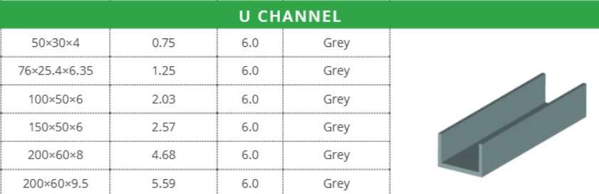
@Iceverge, I’m really grateful for your help on this. I like the idea of all the structural elements being within the VCL. Thank you for showing the build-up stages, rather than one diagram of the finished make up. Although your roof build up is thicker than I’d like, I think I can slim it down a little by replacing your 100 x 50 timbers under the standing seam with 18mm OSB/ply then, if I use the 150mm rafters my SE specified for the roof across the back, rather than the 200mm rafters the arch tec’ drew, the sloping roof at the back is only 29mm thicker than what’s been drawn, which should be easy enough to accommodate in the updated version of the BC/construction drawings. Others may not like the 100mm mineral wall inside the VCL – I’m OK with this if you are. I have two questions about this 100mm mineral wool: 1) Does the mineral wool sit on top of the plasterboard (which is where my arch tec’ has it in his flat roof build ups) or should it be pushed up against the 11mm OSB that’s sitting on top of the rafters? 2) Could I full fill between my rafters with mineral wool? The SE has spec’d 150mm rafters at the back of the house & 200mm rafters at the front. I don’t need a service void above the sloped ceiling sections. I may have got this wrong, but when you say, “cover the entire roof & dormers with a layer of 100mm PIR”, I think you’re suggesting this should include the front dormer wall & cheeks as well, so the build-up is much the same as the roof you’ve drawn, but with the stud walls fully filled with insulation – is that right? If so, I don’t much like the idea of my cross battens that will support my vertical cladding, hanging off 100mm of PIR - that would make the PIR a structural element. I have seen C-shaped structural GRP channels, around 100mm deep, so I could investigate the cost of using these, vertically, against the outside of the dormer stud walls. I could then cover the outside of the studs with PIR, tucked into the C-channels, cover all this structure in breather membrane, then affix my cross battens & cladding. If all of the above is feasible then I could delete my arch tec’s dormer wall spec’ element, “140mm PIR cut in between studs at 400 centres”, & replace this with 140mm mineral wool, which would be much easier to fit between studs & noggins than PIR, leaving no air gaps & providing the added benefit of sound insulation. I realise there’d still be some cutting of PIR to do around the outside, but there’d be no noggins & we could fit the first GRP channel, then the first board, then fit the next channel, pushing it up against the previous board – sounds easy.
-
The point @SBMS & I are trying to make is: if you fill in No 6, so you're asking Ubakus about a roof, rather than just the lower part of a roof, Ubakus will say it's not OK.