MortarThePoint
-
Posts
2168 -
Joined
-
Last visited
Everything posted by MortarThePoint
-
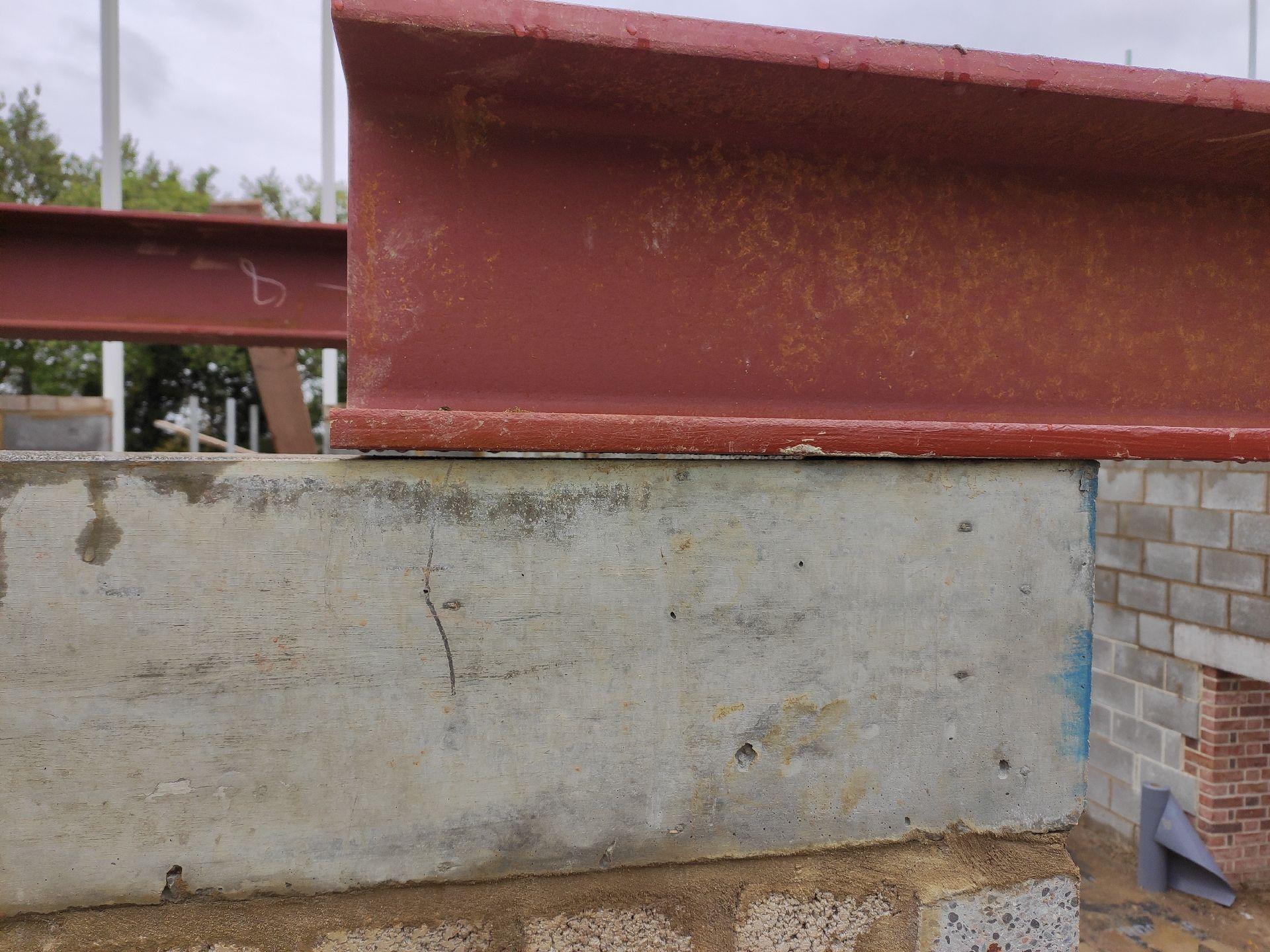
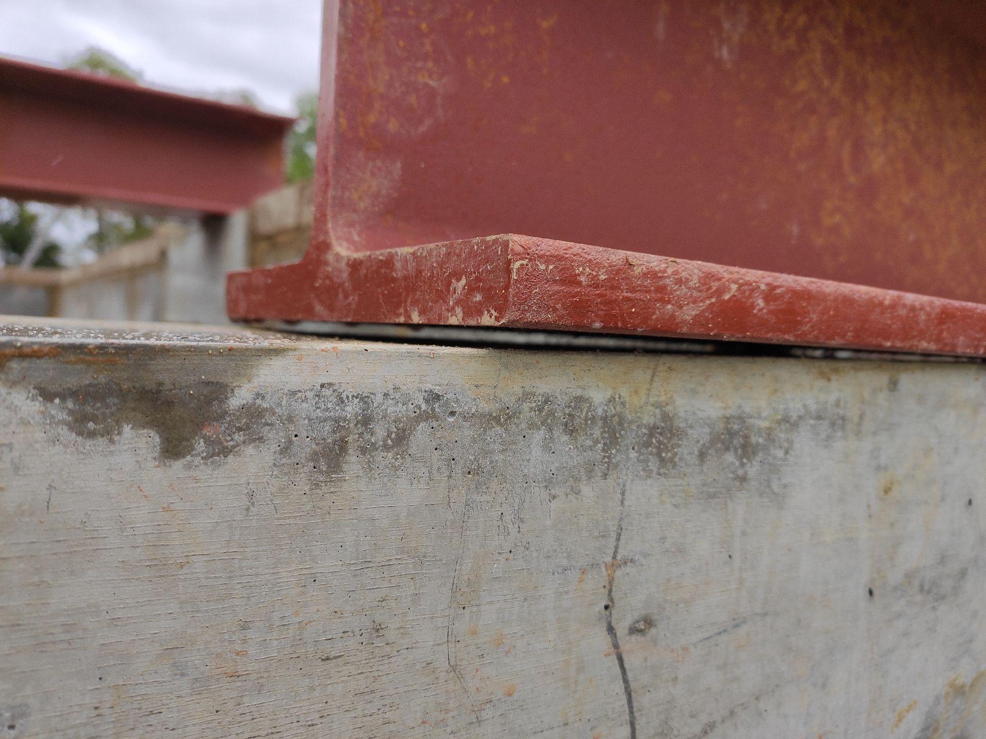
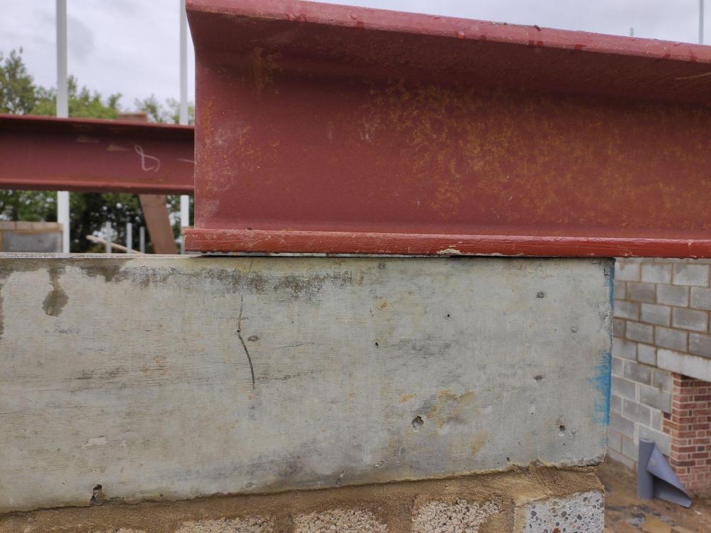
We've just installed some steel beams (UC 203x203x86). One padstone looks to be a bit out of level and across the 400mm opens up a gap of about 3 mm. Is this a worry? If so what should be done to fix it? For reference, the bottom flange of the beam is 20.5mm in height. The padstones are large and heavy (660x190x215, about 65kg) so getting them perfectly level would always be a challenge.

-
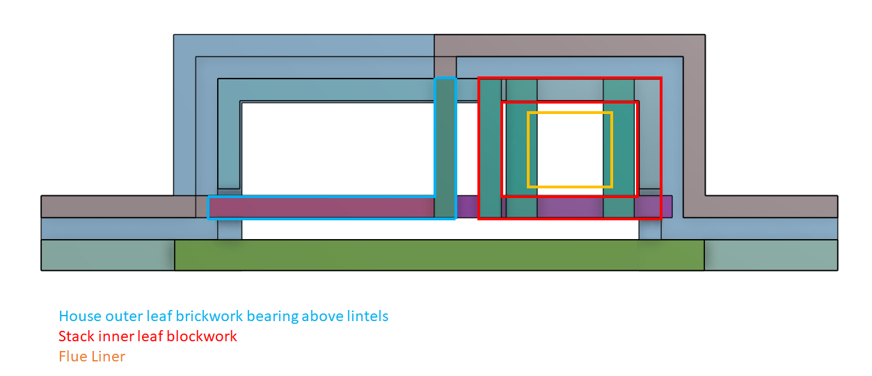
The tiredness is getting to me, a six month old and self building is a killer combo. Measuring an elevation drawing (at 1:50 scale) it has the chimney wall on the house side above the inner leaf of the house wall, not the outer leaf. Ignore the drawing in my last post. My comment was correct as it's referring to the blockwork of the chimney needing to align with the house wall outer leaf. Up to wallplate through, there shouldn't be any reason the chimney can't join the house's inner leaf as @Mr Punter suggests. I still need the PURPLE lintel to be strong to support the house wall outer leaf where it bears on it. Joining the chimney stack blockwork to the house inner leaf below first floor level would increase the load on the GREEN lintel a bit. Elevation View: Plan View:
-
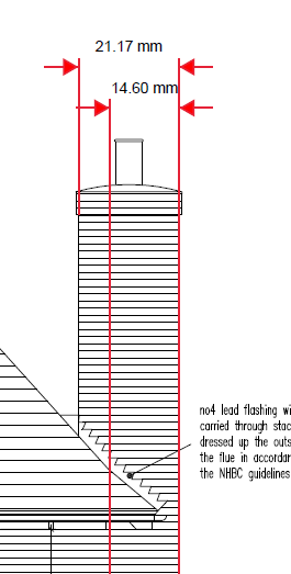
It does seem more sensible doesn't it. I don't know why the Architect has insulation there. It would have to transition back to the Architect's plan at wall plate so that the wall of the chimney on the house side is back aligned with the outer leaf of the house wall. Otherwise the chimney would end up much squarer above roof level than originally planned. That would involve some lintels at wall plate level though which doesn't seem an issue. I have shown the outside edges of the chimney brickwork above roof level in RED:
-
I'm increasing thinking the insulation between the house and the chimney is pointless and results in a lot of complications.
-
Its always struck me as a bit nuts that the chimney stack inner blockwork is insulated from the house. That's how the Architect designed it. It would take a lot of load off the PURPLE lintel if that blockwork tied in to the house inner leaf.
-
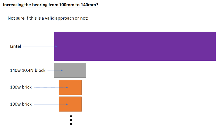
One thing I am not so keen on is the PURPLE lintel bears on a 100mm wide wall effectively. It must be stabilised a lot by the corner with the 140mm blockwork, but it's always nice to think of something bearing on a fat wall. The bearing itself can be improved by widening the wall slightly as shown below.
-
I described the setup and gave some of the images to lintel suppliers. I shared more about my thoughts on the GREEN lintel, but didn't want to 'lead the witness' on the PURPLE lintel so just shared images and load numbers. For the GREEN lintel, one supplier said a 140w x 140h lintel would be OK, whilst another recommended a 140w x 215h lintel saying it would triangulate, but did his calculations based on it not to be on the safe side. For the PURPLE lintel, the same first supplier recommended a 100w x 215h lintel and the other said to consult a Structural Engineer.
-
I know what you mean there, but I tried to get the Structural Engineer to do it all at first and then did it my self out of despiration. I should have said he didn't show much interest in the whole area.
-
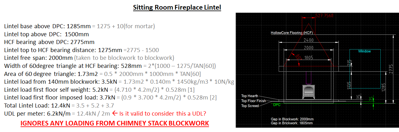
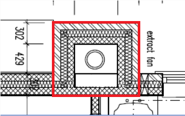
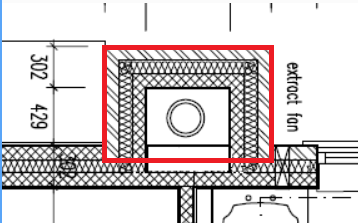
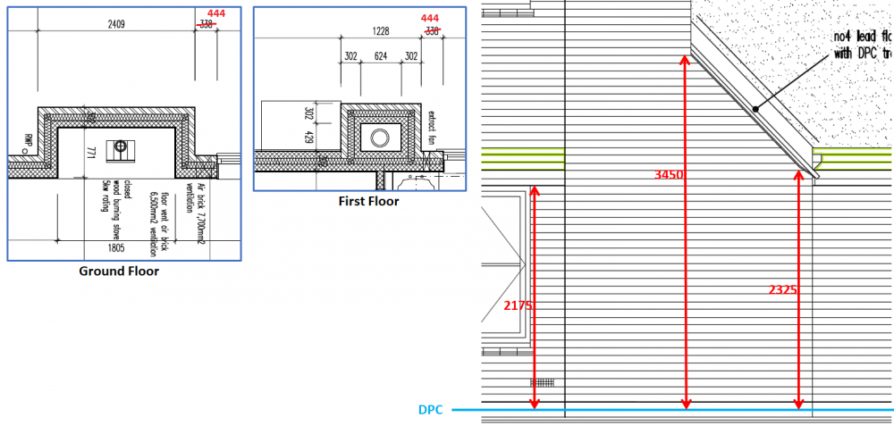
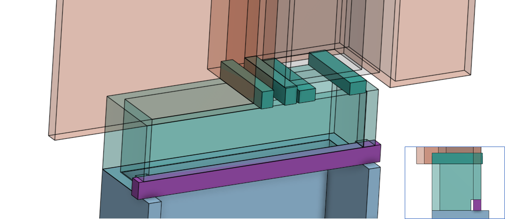
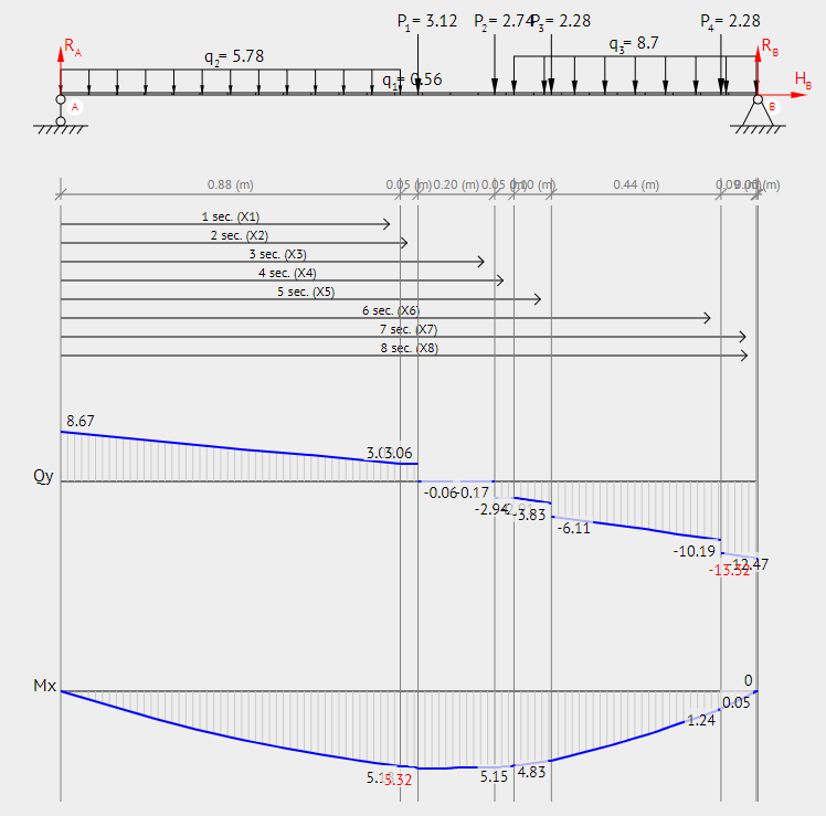
I'm a bit nervous to share this post, but hopefully people will think the design sensible. I designed most of it and I'm not a Structural Engineer so here's hoping I've not made a massive mistake. From the Architect: The design calls for a chimney breast that narrows from 2409mm to 1228mm width. The fireplace opening is 1805mm wide and 1200mm above finished floor, 1125mm above top of hearth. The Flue Arrangement To avoid complex corbelling, discussions with the brickie about how all that is done as well as to allow brickwork to come up, I have decided to make the offset in twin wall flue (i.e. Schiedel ICID). It's a bit nuts, but the flue arrangement is single wall vitreous to twin wall flue to Isokern pumice. Considering the labour etc, the twin wall doesn't actually add much cost and looked to solve a lot of problems. It means the Isokern flue is entirely vertical and can start much higher up. I checked with Schiedel as well as our intended HETAS installer that this is technically possible. Granular fill: I could create a smaller box out of blockwork to be filled with the ganular material (Leca or a perlite substitute) but that would either need much longer ties or increase weight of blockwork. The plan is to construct as in the Architect's drawing and use lots of granular fill. The Lintel Arrangement Well if you thought the flue was complex, there's quite a nest of lintels. House Inner Leaf Lintel: Above that opening there will be a concrete lintel which will be timber dressed. This concrete lintel will be the same width as the house wall inner leaf that it bears on which is 140mm. I chosen to treat it as only bearing on the blockwork rather than the brickwork that actually defines the edge of the reveal. The gap in blockwork is 100mm wider on each side than the fireplace opening, so 2000mm. I calculated the loading on this lintel under two different assumptions: 1) It does triangulate: assuming the blockwork forms an arching action and so I can consider everything in a 60 degree triangle above the lintel. Unfortunately the floor does intersect this triangle so I needed to consider the load from that. The two loads to add are the weight of the 60 degree blockwork triangle and the load from a section of floor bearing the same width as the width of the triangle at that height. Below is the calculation I did. The eagle eyed among you may notice I haven't included the lintel self weight, but that shouldn't tip the balance much. Floor loads from the Structural Engineer's original calculations. 2) It doesn't triangulate: should there be no arching action. I drew a rectangle above the lintel up to and including the floor, but no higher. The maths is much easier: The wall creates a UDL of 1.275m * 0.14m * 1450kg/m3 * 10N/kg = 2.6 kN/m The floor UDL is (4.710kN/m2 + (0.9 * 3.700kN/m2)) * (4.2m / 2) = 16.9 kN/m [4.2m is the floor span] TOTAL UDL: 2.6kN/m + 16.9kN/m = 19.5 kN/m Apparently the rule of thumb is that if the window is over 600mm from the opening then it can be neglected and assumed to triangulate. The distance is 630mm, so I wanted to consider both cases. There are various lintels that could be used to meet the requirement. Some lintels are on crazy lead times these days, but I have chosen a Supreme R21240 which, when used the 21A orientation 140w x 215h), has a load capacity of 47.40 kN/m. Deflection at 1/3 capacity (15.8 kN/m) is 3.41mm, so deflection at 19.5kN/m should be 4.2mm. The triangulated case could perhaps have been met by an R15240 in R15 orientation (140x x 100h) with load capacity of 9.92 kN/m, but I wanted to go beyond that and fancied the R60 fire rating of the R21 lintel. Stack Lintels: this is much more complicated as there are various loads to consider. There need to be lintels at right angles to support the inner leaf of the chimney stack. The main lintel (PURPLE) has to support lintels all these lintels as well as a section of the house's outer leaf brickwork. [NOTE: the GREEN lintel is the one considered above] Listing all the loads on the PURPLE lintel from left to right: 0 to 1805mm : 100mm blockwork, 385mm high (BLUE) : UDL 0.56 kN/m = (0.1m*0.385m*10N/kg*1450kg/m3) 0 to 881mm : house outerleaf brickwork (ORANGE) : UDL 5.78 kN/m = (0.1m*3.5m*10N/kg*1650kg/m3) at 927mm : left hand lintel that supports outer leaf brickwork return : point load 3.12 kN = (0.1m*0.631m*6m*10N/kg*1650kg/m3) / 2 at 1126mm : lintel bearing that supports the side of the stack inner blockwork (GREY): point load 2.74 kN = (0.1m*0.624m*6m*10N/kg*1450kg/m3) / 2 at 1273mm : lintel bearing half the weight of the flue liner and surrounding granular fill : point load 2.28 kN = (9.1kN / 2) / 2 1176mm to 1805mm : stack inner blockwork (GREY) : UDL 8.7 kN/m = (0.1m*6m*10N/kg*1450kg/m3) at 1713mm : lintel bearing other half of the weight of the flue liner and surrounding granular fill* : point load 2.28 kN = (9.1kN / 2) / 2 * weight of flue liner and granular fill: weight of liner : 1.1kN = ((11kg/unit * 6m * 10N /kg) / (0.6m/unit)) weight of granular fill : 8 kN = (0.429m*0.624m*6m*500kg/m3*10N/kg) [assumed 500kg/m, Leca seems to be about 400kg/m3 I think] TOTAL : 9.1 kN = (1.1kN+8kN) Total load on lintel: 22.0 kN = ((0.56*1.805) + (5.78*0.881) + 3.12 + 2.74 + 2.28 + (8.7*0.629) + 2.28) Quick worst case calculation by putting full load at lintel mid-span. The maximum moment from a point load mid-span is double the moment of the same load spread as a UDL I believe. Therefore equivalent UDL is 24.4kN/m = (22.0kN * 2 / 1.805m) That's a bit scary! A more considered calculation: I want an equivalent UDL loading to compare with lintel specifications. A UDL across a beam has a maximum bending moment of M_max = q * L2 / 8 . rearranging gives q = M_max * 8 / L2 . Putting in the maximum moment from BeamGuru gives q = 5.32kNm * 8 / (1.805m*1.805m) = 13.1 kN/m. That's much better ? A 2100mm Naylor R9 lintel has a stated Allowable Load of 25.78 kN/m with 1800mm free span. This is very nearly double what is calculated here. I expect there would be some load spreading onto surrounding walls as well reducing the loading on the lintel, but I don't understand all the mechanics of that, so have tried to keep the calculation worst case. There would be some load spread by the blockwork between the BLUE lintels and the PURPLE one, but I wanted to consider the case similar to not having that blockwork. I might repeat the calculation assuming 45 degree load spreading under the BLUE lintels. These lintels have short free spans (424mm) and are chosen to match masonry of help support the flue base. The Structural Engineer hasn't shown much interest in all this when I have tried to get him to take a look. Tools: QCAD, OnShape, BeamGuru.com


-
I'm writing a big post about all my chimney and flue design journey which has been a bit involved to say the least
-
Cool, thanks
-
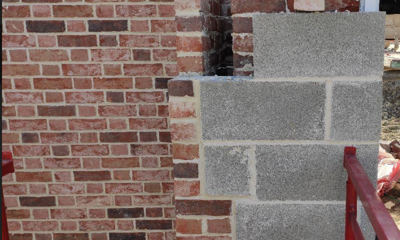
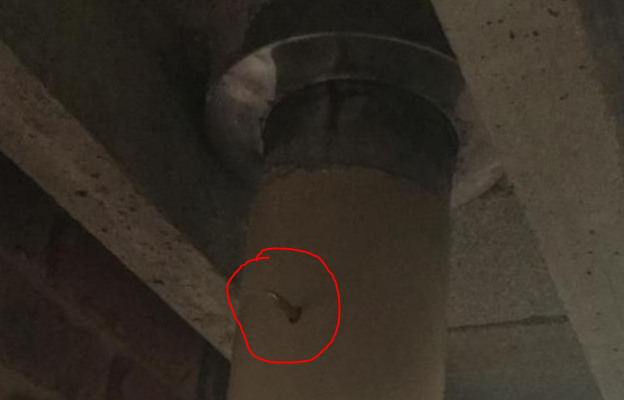
That's looks really good, well done! I'm curious, what's this:
-
Very useful! Did you not have the metal support plate to go between the concrete base block and the lintels? I've seen adjustable length vitreous pipes which I guess would help with fitting.
-
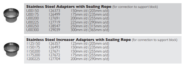
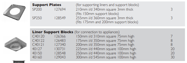
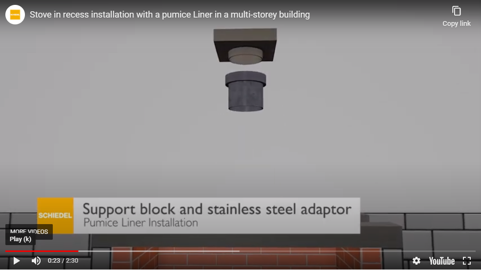
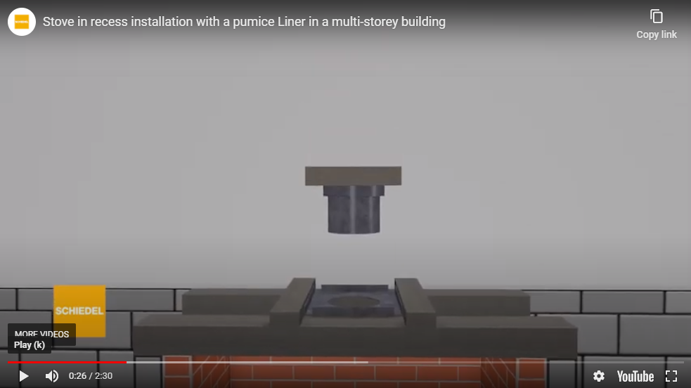
Cheers @joe90 ! The two images in my original post are from the same installation video about 5 seconds apart. So can the wider ring part of the adaptor fit through the hole in the support plate? If I understand the dimensions in the extracts below, the hole in the support plate is 255mm in diameter and the wider ring of the adaptor is o/d 235mm so should fit through. I guess it's going to be cozy up their between the lintels though as there is only a 300mm gap so not much room to see that a good job has been done. What stops this adaptor falling off due to gravity before the lower flue is added? Is it a tight push fit? ------ Copied from: https://directflues.co.uk/images/store/brochures/brochure-isokern-schiedel.pdf
-
Does anyone know if the "stainless steel adaptor" has to be added before the support block is lowered onto the support plate? I placed an order for Monday delivery and we'll be working on it then. I asked if I had all the bits I need for the actual flue installation and they said yes, but may not have noticed I didn't order the stainless steel adaptor. I might be able to ask my wife to go and collect one on Monday first thing if I know I need it. Below are some screenshots of the Isokern website. If the adaptor can be added after the full flue install then I can rest easy.
-
Ideas how to avoid the void
MortarThePoint replied to MortarThePoint's topic in General Construction Issues
I plan to seal the cores at the cavity end so hopefully that will help -
Ideas how to avoid the void
MortarThePoint replied to MortarThePoint's topic in General Construction Issues
We're going for UFH with air source heat pump. We won't need quick heat so I'm happy to not insulate between the UFH and the hollowcore. Do you think that's a mistake? -
Ideas how to avoid the void
MortarThePoint replied to MortarThePoint's topic in General Construction Issues
I think it would be possible for me to limit myself to going along the long axis of the planks. I think I can chase a channel into the underside of the plank and route the cable in there. I asked if they could cast a channel in, but no cigar. Some other manufacturers allow that I think. Alternatively, I can drill an up to 68mm hole through the surface into the core and use that as a conduit. You have to do it in the correct place to not hit a rebar and reduce the plank's strength. That said, my designer was happy that any single bar could be knocked out without an issue. If the finish can look top notch I think it's really worth considering as I'm not keen on voids in general. Might have something to do with having lived in places where mice have enjoyed running around in them at night. Saves a lot of effort and gives a bit more ceiling height, though I don't think we need the height. -
Ideas how to avoid the void
MortarThePoint replied to MortarThePoint's topic in General Construction Issues
Interesting thanks! Does it give a good finish you'd be happy with in your own home or can you see the camber of the planks or anything? -
Ideas how to avoid the void
MortarThePoint replied to MortarThePoint's topic in General Construction Issues
I agree, we don't want the industrial aesthetic. If the ceiling can be wet plastered and if the mains cables can be recessed into rebates in the underside of the slabs, then it might work. That's two big ifs and a might though. ? -
Ideas how to avoid the void
MortarThePoint replied to MortarThePoint's topic in General Construction Issues
I haven't managed to speak to the flooring designer, but I did see this link and this link which make sense. We're not using them, but Longley say: "Textured paint finishes or plaster finishes may be applied to Hollowcore planks in accordance with the manufacturer’s instructions. Plaster manufacturers may require the application of a bonding agent. (Plastered finishes are not recommended for longer spans)." https://www.longley.uk.com/products/hollowcore/finishes-service-runs/ Not clear what classes as a longer span, but that's likely to do with the camber the planks have. I'll ask our guys if it is possible to chase slots in the underside of the hollow core as even a 5mm deep slot would be enough to hide the wire to a light or smoke alarm. -
Ideas how to avoid the void
MortarThePoint replied to MortarThePoint's topic in General Construction Issues
I will ask the designer, but I'm sure it's not the normal way to go. -
Ideas how to avoid the void
MortarThePoint replied to MortarThePoint's topic in General Construction Issues
I haven't no. Sounds like this could be the killer to the idea -
Ideas how to avoid the void
MortarThePoint replied to MortarThePoint's topic in General Construction Issues
You don't think that wet plastering the underside of the concrete floor could take out the unlevelness? Any void size effectively comes with the same cost and effort consequences. -
We're having a precast concrete hollow core floor as our first floor. The Architect has designed it so that there is a ceiling void and as I see it this is 'only' to allow the routing of services and drainage: mains cables - to whole house, but I guess these could be routed up to the first floor ceiling and then down from there hot and cold water - pretty localised at one end of the house in the first floor. There is one bathroom at the far end of the house, but I guess pipes could pass above the first floor ceiling and then back down? drainage - except for showers, this can easily be dealt with above the floor as although their is a separate loo at the far end of the house, its drainage exits through an exterior wall. At that far end we would have to have a raised shower tray, but at the other end everything is very close together so could be routed through a cast in hole in the precast slab lights - down lighters all need a void to sit in as far as i can tell. regardless of whether the light itself needs a void, if the light is in the ceiling then a mains cable needs to reach it. Could I route this through the first floor screed? mains powered smoke alarms - the alarm itself but also its mains feed. There's a lot of work and cost required to install the ceiling void and I am starting to think it could be designed out. The biggest two hurdles would be ceiling lights and mains smoke alarms. I guess if these are kept low voltage, then I could have some pretty flat cables that go into the plaster?? What do people think, any good ideas? The obvious solution is below, but it's not acceptable aesthetically: