marshian
-
Posts
1605 -
Joined
-
Last visited
-
Days Won
6
Everything posted by marshian
-
In other news Gas Engineer has had it confirmed from Viessmann that boiler (in current configuration) needs a switched live from the programmer to the boiler - at bloody last!!!
-
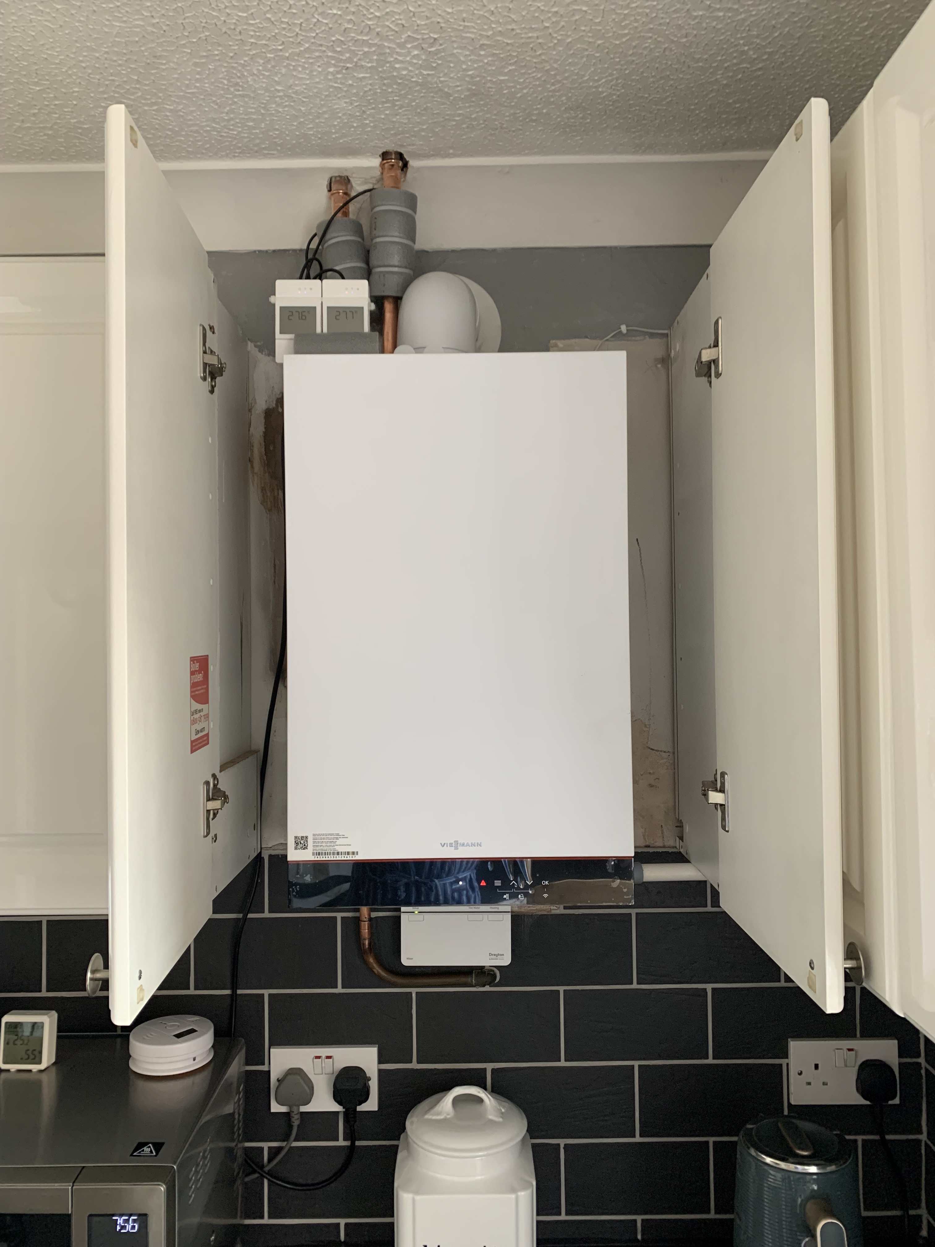
Well my old school plan had a flaw - it wouldn't have been a problem if the gas engineer had used my 3 port valve as I proposed with no mid position in the old airing cupboard arrangement because I only had a bypass fitted for the CH side - HW didn't need one because the flow rate was always far higher (easiest path and all that) However now I have a bypass that will work if pressure in the system is high with CH or HW - closing the gate valve to increase the amount of time the water stays in the coil and reduce the return temp to the boiler is enough pressure to cause the bypass to want to play (By play I mean get involved) So tonight I've been experimenting with pump parameters to see if I can find a pump setting that Provides a min of 0.4 m3/Hr so that the boiler is happy with the level of flow (below 0.4 m3/hr the boiler gets a bit fussy and throws the odd "low flow" fault) when circuit is at it's smallest (ie just one or two rads in circuit) And provides a max of 750 - 800 l/hr (0.8 m3/hr) when all the rads are calling for heat so the boiler can ramp up and get the circuit up to temp Because the alternative plan is fit a NO zone valve in the bypass line so it closes at the same time as the CH NO zone valve........... Anyway no one wants to see a load of tables of what pump results in terms of watts, head and m3/hr is like for 3 different pump operating modes each with 3 different speed settings for both all rads calling for heat and a very tight circuit where I'm left with just two rads still calling (Bypass was closed for this) so I'll just say I've found a setting that meets the requirements but I haven't done HW on it yet.
-

Gas boiler vs ASHP & short cycling in low heat loss property
marshian replied to ruggers's topic in Other Heating Systems
First question - OK - there probably is an option to change temp or power on a Viessmann 4 pipe boiler but I don't have one of those - I have a two pipe "dumb" boiler with Viessmann "Extras" (actually calling it "dumb" is unfair it's really surprised me with just how clever the program in it is....... I think I've explained elsewhere reasons why I chose the 100-W heat only I couldn't fit a larger boiler in the space I have and hide it in a cupboard I didn't want to run another set of flow and return pipes for the system boiler Only the 100-W has flow and return exiting the boiler at the top (same as my old boiler) So I was pretty much picking what worked best for location and minimal changeover costs I've found a way to rein in the boiler modulation when doing HW, it's a bit old school but it's almost done the job (like everything it's a swings an roundabouts situation - or you could say actions have consequences but I've got a back up plan) Second Question - Temp wise it's 80 deg that's what the boiler targets I have the cyl stat set to 60 deg (it ends up at 63 on a friday legionaires cycle) and that's the only time the cyl stat actually gets to be in control - rest of the time - I have HW set to 20 mins on a timed slot - hence my end of HW temps can vary a little (anywhere between 46 and 54 depending on tank starting temp) but I can live with that. I always heat water before it's needed, I never have a HW demand at the same time as water heating I think the Cyl Stat hysteresis is quite wide - It's just a std Dayton HTS3 probably around 8 deg it also doesn't like being set below 50 deg as it doesn't have a positive off so it's really easy to think you've cracked a position for 45 deg and then find you have no HW because the next day it's Off I don't have an NTS sensor It's how I've always done HW always happy to hear alternatives to my current process but what I do works for us in the house. Sorry probably a bit wordy in reply!!! -
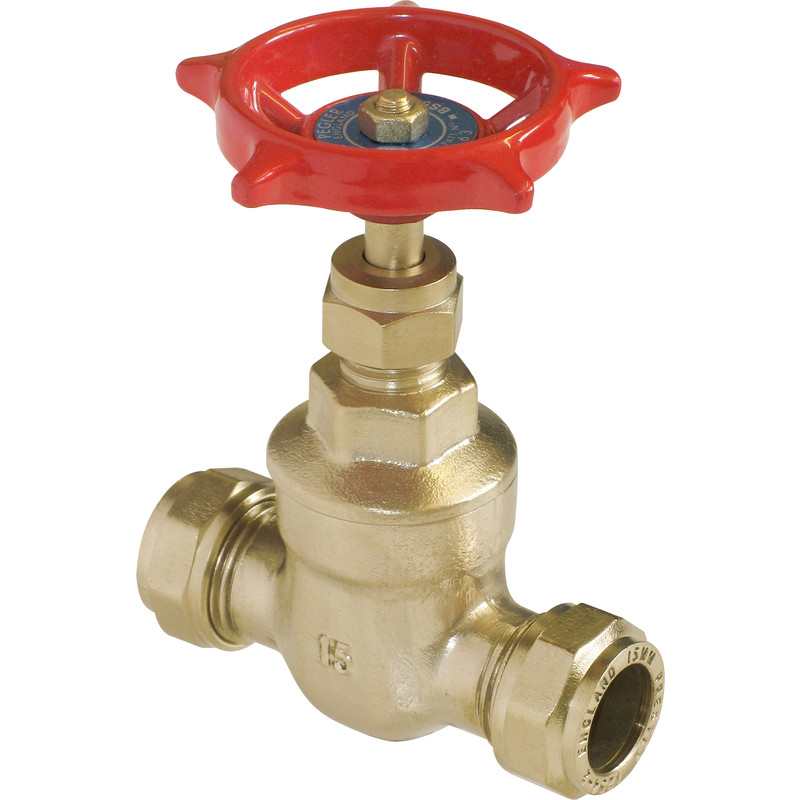
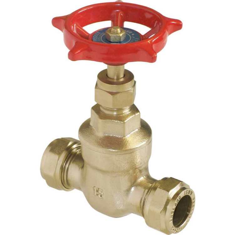
So Viessmann Hot water demand box throws 80 deg C at the HW coil and ramps up to 100% Yes water reheat times are super quick but the boiler is quite noisy when it does HW and the tank only really can cope with 3-8 kW without the return temps being 10 deg less than the flow (Old boiler min was 10kW and that gave similar HW times to the viessmann when I ran it at 80 Deg C to get the water done without cycling) So if the boiler modulates based on return temps or flow (or both) Hello gate valve - happy to have you join the party - lets shut you down a little and see what happens 80 Deg C flow - boiler initially hit 100% but as I closed the valve it modulated down to 30% - 20 deg difference between flow and return (76 deg flow 56 deg return) - water heated from 20 deg to 52 deg in 22 mins It was a bit shunty to start with till I found a place where the boiler wasn't overshooting ramping down and then as the flow temp dropped too much throwing much higher kW at the circuit again Basically 1 turn open from closed seems to work fine - that'll do for starters
-
Gas boiler vs ASHP & short cycling in low heat loss property
marshian replied to ruggers's topic in Other Heating Systems
Gone old school and found a way forward to cap the boilers output - can't stop it going to 80 deg or trying to shove 20kW at the Hot Water circuit with the Demand Box parameters but I'll update that in my Viessmann Boiler thread. -
Gas boiler vs ASHP & short cycling in low heat loss property
marshian replied to ruggers's topic in Other Heating Systems
Clarification if I wasn’t clear (I thought I was but apparently not) return pipe hotter than flow when the boiler is “off” I have probes on flow and return pipes after several hours of no boiler activity the temp in the return pipe above the boiler is higher thsn the flow - I believed this was down to thermo circulation - hot moving to cold the addition of s london loop has stopped it “dead”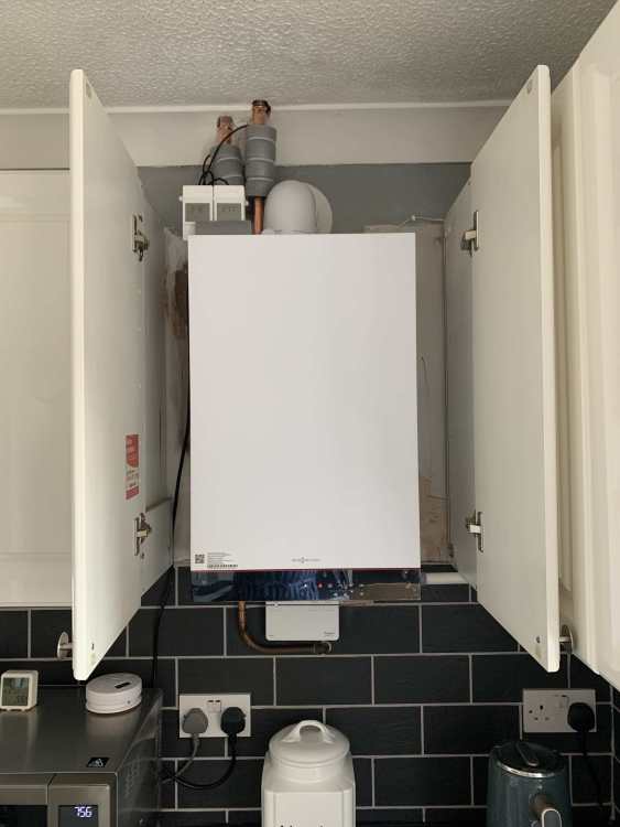
-
Gas boiler vs ASHP & short cycling in low heat loss property
marshian replied to ruggers's topic in Other Heating Systems
to round this slight off topic element off - london loop fitted to return from coil - was a right pain to make and fit because of space constraints in the airing cupboard but I normally see 0.66 deg tank loss per hour (it used to be 1 deg per hour before I reconfigured the zone valves) 1900 hrs yesterday - heated the tank to 50 deg - at 8am this morning it had dropped to 46 deg (no major consumption of HW during that time) 0.3 deg loss per hour is an improvement The biggest obvious sign was that flow and return pipes at the boiler were identical - normally I see a higher return pipe temp before I even start space heating I don’t need one on the top of the coil because the zone valve is right next to the coil inlet. I might have to put one on the HW tank outlet now as that’s probably another driver for the losses. -
Can you help me find the right 17mm socket to change this valve
marshian replied to Adsibob's topic in General Plumbing
Some spark plugs are 17mm so it shouldn’t be hard to find a box spanner or a spark plug socket - they are extended length -
Gas boiler vs ASHP & short cycling in low heat loss property
marshian replied to ruggers's topic in Other Heating Systems
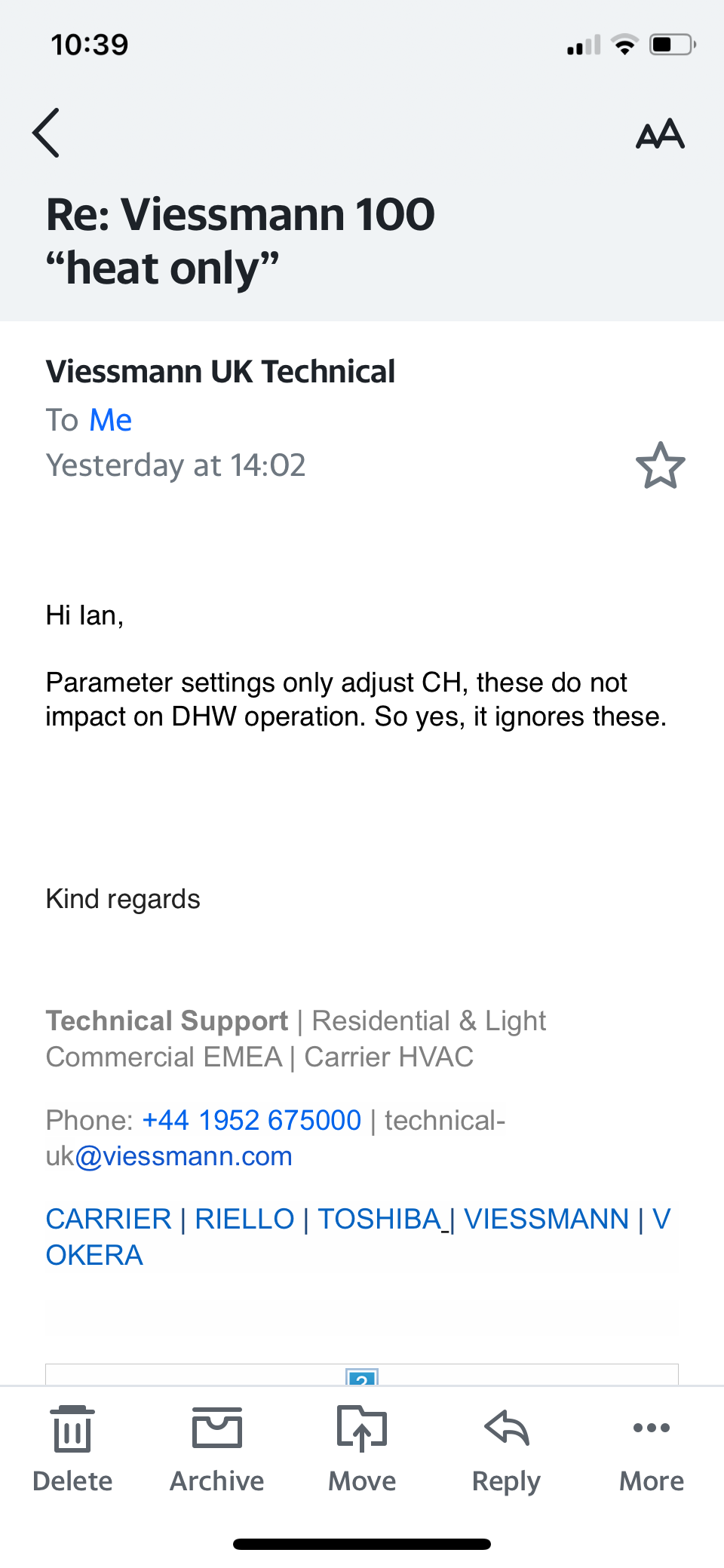
Oh and below is the response from Viessmann technical regarding range rating the boiler (I have another email confirming the same for flow temp max, also adjustable for CH only (not when using HWD box)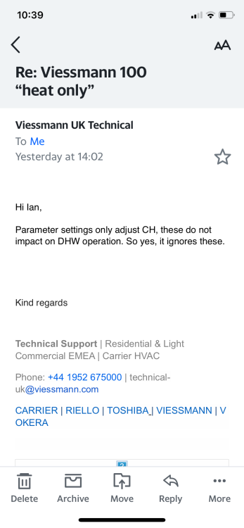
-
Gas boiler vs ASHP & short cycling in low heat loss property
marshian replied to ruggers's topic in Other Heating Systems
Thank you @JohnMo I only really notice the “leaching” when I’ve done the weekly legionaires cycle (an hour or two before some HW is consumed) and when I heat the water much earlier than I need it (like at a weekend when it could be a couple of hours before any water is used) The return side of the cylinder is a bit horrible right now so I’d like to tidy it up and this would be the ideal time to stick a london loop in - even if it has only a small benefit window I might as well put one in -
Gas boiler vs ASHP & short cycling in low heat loss property
marshian replied to ruggers's topic in Other Heating Systems
Slighly off topic @JohnMo because I can’t find the thread in question when installing a london loop - does it matter if you have to go up 15cm to then go horizontally for min 15 cm then down for 15cm, across horizontally for 15cm and then up for 15cm? I can’t fit a london loop on my HW tank return without doing this as I’d have to go down into the floor and through a floor joist - if I go up first I can package a london loop easier - it won’t look pretty but it can be done -
Gas boiler vs ASHP & short cycling in low heat loss property
marshian replied to ruggers's topic in Other Heating Systems
I asked Viessmann technical help if I could 1. set the max flow temp lower for HW (when demand box was being used) their response was no - it’s preset to max flow temp 2. Use the max output setting on the boiler (range rate effectively) to reduce the kW being used when doing HW (using the demand box) their response was no - this would only impact the CH side the demand box calls for max boiler output and only modulates down when the return temps mean it has too. As a result I shall do what I said I would do earlier in the thread and in none heating months switch back to dumb boiler mode. I will say it’s reheat time is bloody fast - this morning tank was 20 deg C (we’d used all the water yesterday - bath night) and in 18 mins it was 54 deg - I don’t need that speed in the summer 🙂 -
Gas boiler vs ASHP & short cycling in low heat loss property
marshian replied to ruggers's topic in Other Heating Systems
Because DHWP maximises efficiency on CH but sacrifices a small amount of efficiency when heating HW So when you are using CH the gains on CH running weather comp flow temps out weigh the drop in efficiency when doing HW In the summer you have no need to use CH so I can revert the boiler to non DHWP and run the flow temp at 55 deg C - the boiler runs for 1 hour to get the tank from 25 to 45 (maybe 48 max) it's in condensing mode all the time and the gas usage is lower compared to DHWP when the boiler throws everything at the HW circuit in order to minimise the time spent doing HW and get back to CH asap I've had the opportunity to run the boiler in both modes and I'm pretty sure my data doesn't lie to me. How do you run a heat pump to get the best SCOP or COP - low and slow WC is all about minimising boiler flow temps - keeping the boiler in condensing mode maximises efficiency but to do that and not lose heat in the house you want min down time from heating hence DHWP DMHP for water is actually the exact opposite - chucking everything the boiler has at the HW circuit is not low and slow and there is energy lost to the Flue - why would I want to continue that wasted energy thro the non heating months? -
Gas boiler vs ASHP & short cycling in low heat loss property
marshian replied to ruggers's topic in Other Heating Systems
100-W heat only is two pipe - it doesn’t go down as low as the 200 (min 3.2 kW) I’m using a std vented 115 litre copper cylinder (50 mm foam coated) with basic tank stat so doesn’t have the largest heating coil in it (maybe 3kW max) The boiler does modulate down as the return temps get closer to flow but start of cycle it throws everything it has kW wise (rated at 16kW but my readings from the gas meter over a short period of time says everything is just shy of 21 kW 😉 In summer in the installation settings I’ll just switch the boiler back to dumb (B5 then C7 and then select 13 rather than 4 and it’s back to a normal boiler with full control of the flow temps, no weather compensation and no HW demand function) so in a nutshell no wiring changes -
Gas boiler vs ASHP & short cycling in low heat loss property
marshian replied to ruggers's topic in Other Heating Systems
I have Viessmann 100W "Heat Only" 16 kW with HW demand box and WC It will raise the tank temp from 25 deg C to 50 Deg C in 15-18 mins with a std vented Cylinder Coil In autumn,winter and spring I will run the boiler with DHWP - I want it done in as short a time possible so boiler gets back to CH running weather compensation at low flow temps Summer when I'm only running HW I will revert to heating HW low and slow as there is a small reduction in gas consumption compared to DHWP when the boiler hits the HW as hard as it can Next year I will look to replace the current HW tank for one with a bigger coil (it should shorten the time for HW in any season but enable the boiler to condense better in summer with a lower flow temp) I will experiment with range rating the boiler because I can't lower the flow temp of the boiler (80 deg C) when it's heating HW - it maybe I can't lower the output either but I'll find out soon enough -
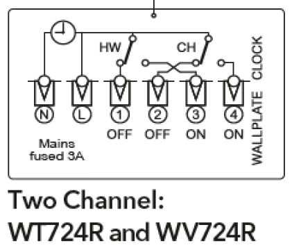
Well time to round this out (Not quite there but damn close) No mater what I did with the Wiser Hub (controller) - All Off, HW On, HW Off, CH On, CH Off or Both CH and HW On the wire from the wiser unit to the wiring centre to trigger the HW was live all the time. I was completely confused by this as it shouldn't be live unless the timer is calling for HW but I checked the wiring instructions and it was all wired correctly 3 for HW and 4 for CH I swapped to a different (spare wire) - same result 240V all the time unless the power to everything was killed The CH wire is only live when the timer and the room stat is calling for heat Every time I check wiring in the wiring centre or remove the Wiser Hub I switch off the power to it all at the Fused Spur that feeds it all I don't know why I did what I did next but I took the Wiser hub off the universal back plate without powering down and I heard an audible click and I stopped - a penny (very large one dropped) - selecting CH or HW had always made an audible click but since the boiler install and change of wiring that had been missing for HW the light comes on but no audible click. I switched off the fused spur - re-attached the Wiser hub and if I selected HW I got a audible click, CH again I got an audible click Going up to the wiring centre with nothing selected on the hub I had no power to either HW or CH signal wires Selecting HW gave me 240 volts and same with CH with nothing selected I got no Volts on either HW or CH My only thought is that somehow the relay or contactor for HW had stuck closed and even powering down the unit was not causing it it open. Anyway everything now works and just need the gas engineer to confirm with Viessmann that a switched live back to the boiler is needed (I'm damn sure it is but I'm not about to fit that) I actually need to think about how the boiler gets that in summer or if heating water outside of the CH period because I can't have both CH and HW linked to the same switched live signal to the boiler or CH will drive HW I might have to either A. think about a relay solution or B. think about a switch (Summer / Winter setting) I can only have one SL wire at the boiler so for Summer the SL comes from the HW side but for winter when I only heat water during the CH timed period it can come from the CH side.
-
And there is my problem - I got the only Viessmann trained gas engineer for 50 mile radius to do the job - the other installer 50 miles away didn't want to quote because the distance made it not worth his while................. Maybe I should ask Adam from heat geek if he fancies a boiler challenge............
-
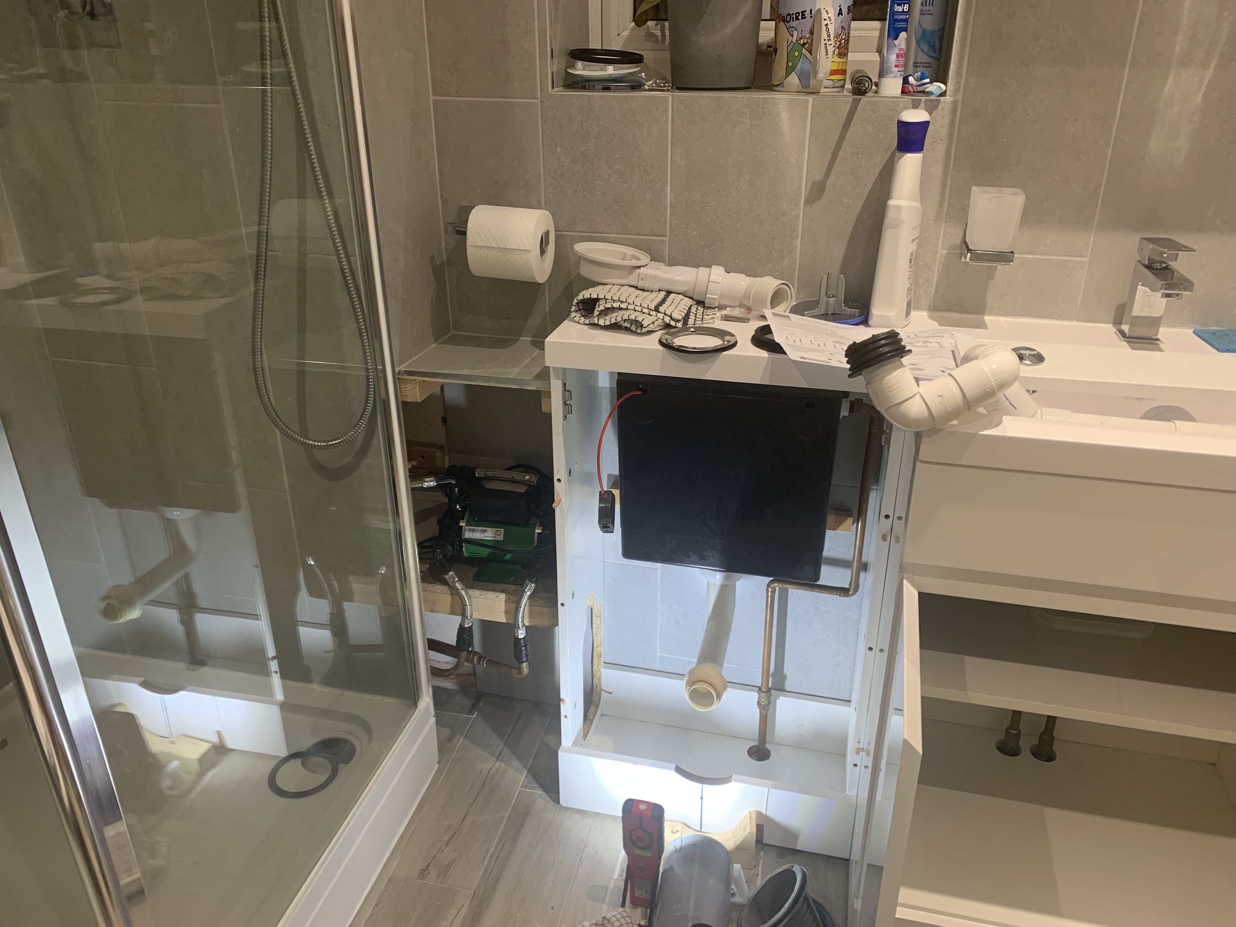
Sorry had to rip apart my bath room to replace a shower waste that was letting in smells So connected (Not me) but AFAIK Outside temp sensor yes HW Demand box Power to the Boiler (Live, Neutral and Earth) After that sorry but not a clue
-
Just to round the calibration element of the thread - I’ve had both sensors over a NaCl slushie for a couple of days at room temp one required an adjustment of 2.7 and the other 4.5 (both cases they were over reading) so I’m a smidge less concerned about my humidity levels now thank you @Sparrowhawk
-
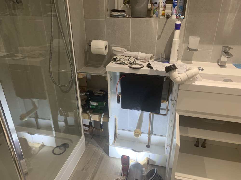
Sorry for slow reply - my attention has been diverted to bathroom issues shower waste needed replacing and access was too tight with the soil pipe in the way - luckily I did the bathroom myself so knew how it all went together Later today I’ll check out the boiler connections
-
as the link is external to the PCB I decided to remove it……. No pump at all
-
Highly likely - That will be down to the gas engineer to resolve - I'm absolutely fine with doing everything outside the boiler - not so fine with stuff inside it.................
-
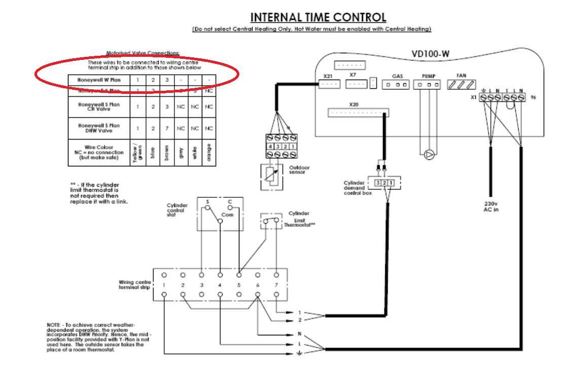
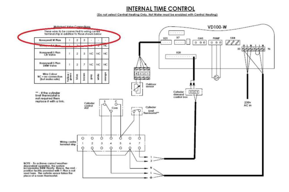
Whoa @JohnMo That link has this diagram - It's not in any of the documentation I got with the boiler or HWD box or weather sensor........... Is a W Plan similar to X plan with a 3 wire NO CH Valve??
-
I’m trying very hard to do three things 1. understand how it works 2. Save the life of a fuse by not getting it wrong 3. Keep the smoke inside the wires thank you for your input but this is not my strong suit so I will be painfully slow in progress
-
What connection?? boiler has Direct control of the pump HWD box wired in Weather Compensation sensor wired in The boiler has been “told” to run in weather compensated operation mode The link wire is still in place and I think it’s running on a permenant live and Neutral only with no switched live in sight But as I’ve said electrickery is not my strong point - if it’s got oil or water in it or it needs to fabricated in steel or wood or whatever I’m fine with it