John Carroll
-
Posts
577 -
Joined
-
Last visited
-
Days Won
3
Everything posted by John Carroll
-
IF you programme the hot water Off does the boiler still continue firing intermittently?, if it doesn't then you may have a faulty cylinder stat or you may have a zone valve end switch not opening even though the vale is closing, the boiler will then keep firing, controlled by its own boiler stat.
-
If its a combi Vaillant and has a HW store, it will begin with a "9", a standard Combi begins with a "8", a non combi system boiler begins with a "6" and a heat only boiler with a external circ pump begins with a "4".
-
My house, 1970 build (Cork) has I'M fairly sure, Hydrodare very heavy walled piping, I found a bit lying about a few years ago and it measured 21mm OD x 11MM ID, that 11mm ID seems a bit strange since we use imperial pipe sizing, its ID is certainly not 1/2", (12.7mm).
-
Pressure Reducing Valves for UVC
John Carroll replied to Spinny's topic in Boilers & Hot Water Tanks
A bit of basic maths might help.... A 22mm PRV will give a flow of around 50LPM at a dP of 1.0bar, ie if the PRV set point pressure (static) is 3.0bar then the outlet pressure will fall to 2.0bar at 50LPM, a 28mm PRV will give a flow of about 100LPM at a dP of 1bar, at a flow of 50LPM the dP will be 1.0*(50/100)^2, 0.25bar, to give a outlet pressure of, 3.0-0.25, 2.75bar. Now going to your flowrate of hardly 25LPM at some outlets, your existing 22mm PRV will have a dP of 1*(25/50)^2, 0.25bar, outlet pressure 3.0-0.25, 2.75bar which means that this particular part of your system requires a dP of 2.75bar to give a flowrate of 25LPM yet the valve is only "opened" 25%, a 28mm PRV will only have a dP of 1*(25/100)^2, 0.0625bar, outlet pressure 3.0-0.065, 2.9375bar, now if you as suggested by your plumber install that 28mm PRV you might think that you will get a substantial increase in flow rate, afraid not, you require a dP of 2.75bar to give a flow of 25LPM but you now have 2.9375bar available to drive more water through the system, but the system pressure will rise with increased flow and the (28mm) PRV pressure will fall until a equilibrium is reached which I reckon is ~ at 2.933bar to give a flow of 25.82LPM, a increase of 0.82LPM, say 1.0LPM, not a lot?, assuming of course that the calcs are anyway correct. -
The EV pre pressure should really be set up by measuring the dynamic pressure with a good flow through the cold taps, (to give say 15/20LPM) after the PRV valve or attached to a (cold) tap fed from the balanced cold on the valve set, which yours are, the prepressure should then be set to say 0.2bar below this, this keeps the diaphragm from bottoming out in any circumstances and also positions it better inside in the EV, IMO. This is probably what happened when the pressure was reduced. It can result in a slightly higher final pressure after a full reheat but this should not be a problem especially since you have a 22L EV on a 252L UVC, If the precharge pressure was 3bar then, after a full cylinder reheat to 60C, the final pressure will be 3.93bar, if the dynamic pressure is 2bar and the EV prepressure is set to 1.8bar then the final pressure will be 4.48bar, a little higher, but not a problem and just may cure noisy operation. I advice(d) the few people I know with UVCs to size the EV to 10% of the UVC capacity and set the prepressure to 2bar anyway even if the dynamic pressure is 3bar.
-
Is this the first "creaking" problem? Did your plumber de pressurise the UVC before repressurising the EV? What make of UVC? What are the capacities of both the UVC and the EV?, should be labeled on both.
-
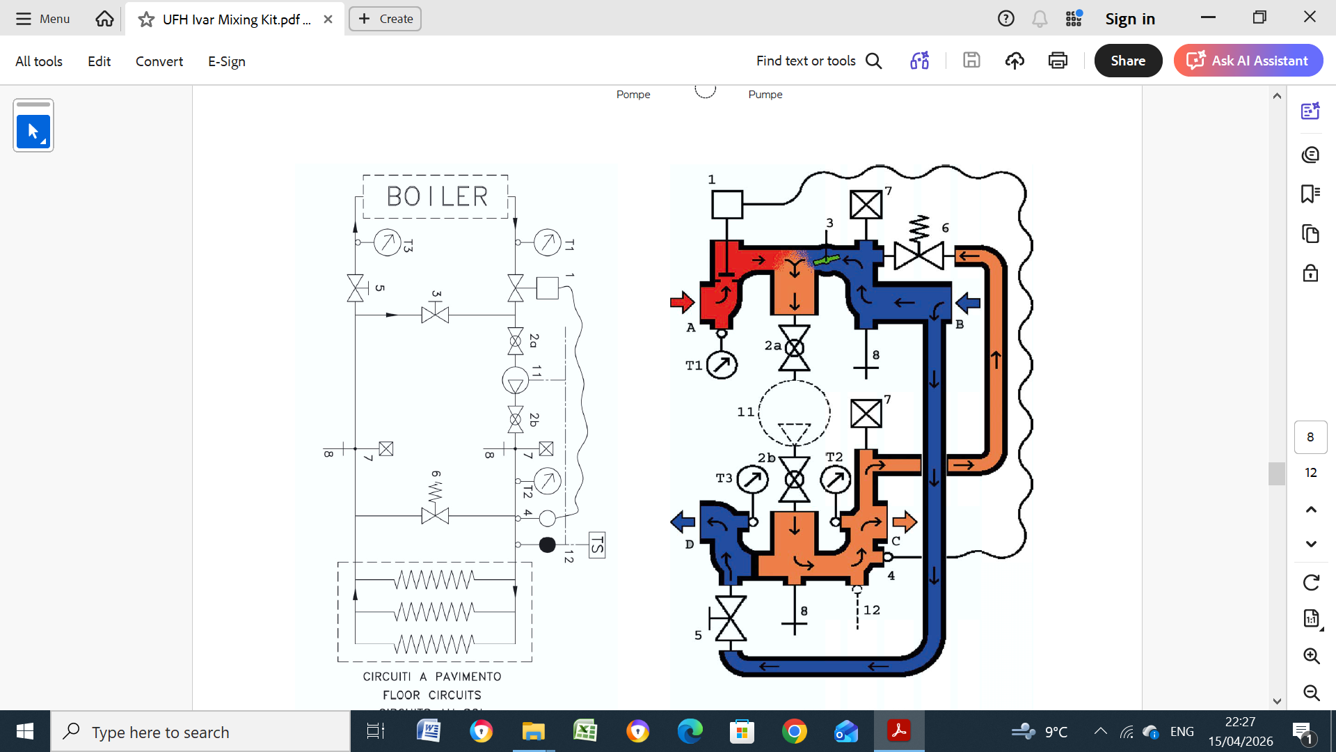
@Nickfromwales posted a shot of this replacement mixing valve in "Drop in Flow Rate" (2022) but didn't say if it cured the problem, it seems a very simple device and one might think that if the valve is moving up/down with the pin that the valve should be wide open to the hot flow with the actuator removed.
-
The MIs show the default mixing (Kv) valve set to 2.5 which "satisfies most demands", although your lower setting, assuming that the lower the setting the more closed off the valve is,would appear to leave less cold water to mix with the hot leading to a hotter mixed flow. MIs, if like yours, below. UFH Ivar Mixing Kit.pdf

-
What is a PITRV?.
-
I must confess that I thought at first that it might work, if one thinks that a BOE works so well even though one might think that in a pumped system that the hot water might just go straight out the opposite bottom end.
-
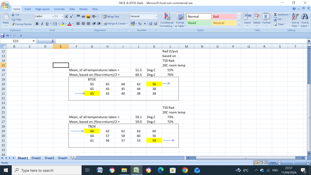
Measuring flow/return temps is generally OK also for calculating rad outputs as long as the plumbing is done correctly, I assisted someone with a HIU system who not only was being overcharged by ~ 30% but was also not getting the required rad output, the heating engineer who came to investigate it insisted that the BTOE system was fine and would work just like TBOE and of course he used the flow+return measurements to "prove" it, to disprove it I piped one of my own rads, below, using both methods, they then plumbed up the system correctly.
-
Some column rads must have the flow at one particular end because they may have a flow diverter, they may have a arrow somewhere, if not you could try one of these, of suitable length, it force the water up through one column, it will then flow down equally through the remaining 2 or 3 columns. Are they (column) hot along the bottom and cool along the top??.
-
If the boiler is continuously running at 4.1kWh gas consumption and the output by my calc is 3.924kW then it adds up fairly well as this gives a boiler efficiency of 95.71%. You mentioned somewhere I think that you thought your boiler's minimum output should be better as its not achieving its advertised figure of 3.2kW at 50C/30C, which means the gas consumption should be 3.2/0.9571, 3.343kWh?, what do you reckon is the minimum gas consumption when it starts cycling?
-
Assuming a average 19.25C room(s) temp and 0.6m3/hr then 21.87kW ofT50s will result in 3.924kW of T13.337s, 17.944% output, but with flow/return/dT of 35.4C/29.77C/5.63C, sounds more reasonable? And for interest if the flowrate is slowed to 0.36m3/hr with 19.25C roomtemps and 35.4C flowtemp then, the output falls to 3.44kW with flow/return/dT of 35.4C/27.19C/8.21C, the difference between 3.924kw & 3.44kW might just be enough to tip the scales into boiler recycle??.
-
You had a few readings there early in January of flow/return/dT, 35.4C/29.0C/6.4C, by calculation and assuming 20C room temps at I think you said a flowrate of 0.5m3/hr then the rads are 12.199 deg rads with a output of 15.98% and you require a unlikely 23.28kW of T50 rads which will result in a output of 3.72kW, something not right there. if calcs correct, maybe flowrate??
-
At a OAT of 10C the Targettemp is 23C, the end temp is 29.5C, TT+ 6.5C At a OAT 0f 2C the Targettemp is 31C, the end temp is 32.7C, TT+ 1.7C At a OAT of 10C the burner shuts down at TT+6.5C, is this because its exceeded TT+5C? At a OAT of 2C the burner shuts down at TT+1.7C, why? Does the boiler (FT)ever run at the the TT??.
-
My understanding of boiler controls then is fairly radically different to the above, my understanding is that the boiler looks at the difference between the target flow temp and the actual flow temp, if the flow temp is < the target temp then the boiler will eventually fire flat out until the flow temp is the same as the target temp or slightly exceeds it, the boiler will then modulate down until the target flow temp and the actual flow temp are almost exactly the same, if the heat demand is < the minimum boiler output then the boier return temp will start increasing which in turn means that the flow temperature will increase until eventually it may exceed the target flow temp by 5C, the burner will then trip, the circ ump will continue to run and the burner will then refire when tha anticycle time has elapsed. Boilers like the Valliant do have return temperature monitoring and if the DT between the flow and return temps exceeds something like 27C/30C will pause the increase in modulation or take some action like this until the dT decreases, their fairly recent system boilers have various pump settings, one of which allows you to set the flow/return dT between 10C and 20C, it achieves this by changing the pump speed which changes the circulation flwrate but does not interfere with the target flow templ/actual flow temp control.
-
But if you have steady state running and the target/flow dT increases to 5C can only mean that the heat demand is lower than the boiler minimum output?
-
If the heat demand is/was steady and if the boiler is not at minimum modulation then one might expect a very low target/flow temp dT of max 1 or 2C, I've often looked my daughter's Vokera and its almost allways spot on, biggest dT I've ever seen is 1C. Also, when you were decreasing the targettemp back down to 27C, (from 43C) were you keeping the dT < 5C while adjusting, otherwise the burner should have tripped?.
-
Even though the targettemp is remotely (weather compensated) set and presumably not jumping around, can/have you set the targettemp manually high enough to ensure the heat demand is slightly higher than the boiler's minimum output to prevent burner cut out and recycling and see does the boiler behave under these conditions, if not, then. IMO, a boiler control problem?. Can you post any trends?
-
At 00:20:18, boiler modulates to minimum and at 00:21:45 shuts down due to flowtemp being targettemp+5C, isn't this quite normal behaviour??
-
Here's a dynamic version to check your own systems. Residual Pump Heads Rev1.xlsx
-
I’ve been asked numerous times to explain the residual pump curves published in some Vaillant Ecotec Boilers MIs, I’ve looked at them several times but afraid I can’t make any sense of them. Someone on here might explain them or/and post similar curves from their (Vaillant) HP circ pump curves, if available. The first screenshot shows my calcs based on a typical 7M circ pump, second screenshot is the Vaillants and the third is unknown but does make sense. The Vaillant’s constant pressure residual default setting is 250mB, 2.5M. At this setting, mine shows a flowrate of 1200LPH (20.0LPM), unknown’s 1300LPH & vaillant’s 1230LPH, much of a much. At 70% pump speed (72% for unknown’s but won’t have any big effect vs 70%) mine = 540LPH (9.0LPM), unknown = 620LPH (10.3LPM), again not hughely different and probably explained by pump differences but Vaillant = 1150LPH (19.2LPM), can’t figure this out but one would think Vaillant have some basis for publishing these figures??. Residual Head.docx
-
Worcester Bosch Greenstar 8000 System Boiler Issues
John Carroll replied to EinTopaz's topic in Boilers & Hot Water Tanks
-
Worcester Bosch Greenstar 8000 System Boiler Issues
John Carroll replied to EinTopaz's topic in Boilers & Hot Water Tanks
The boiler's behaviour in reaching 100% output seems quite reasonable IMO, 5 minutes to reach 75% and a further 5 minutes to reach 100%, my daughters Vokera Vision 20S is pretty similar except, as it states, in the MIs.... it takes another 10 minutes to increase the output from 75% to 100%., it probably doesn't take quite 5 minutes to reach 75% but ~ 2 or 3, not a whole not different. But it certainly behaves much differently once the targettemp is reached, it immediately ramps down to maintain the targettemp very accurately, if one zone is switched off, the flowtemp might rise by a max of 2C and then returns to exactly its targettemp. This would be my bone of contention with WB. It shouldn't matter where the "flow" temperature is being measured, the controller is looking at this temperature and should modulate the boiler output to maintain the targettemp. What is the offset now between the Boiler displayed flowtemperature and the targettemp? and how does your temperature sensor, (if installed), compare with the boiler displayed one?. If you change the targettemp up or down by say 3C, is the boiler sluggish in responding and is there overshoot and undershoot?. I seem to remember that before the HEX replacement that the targettemp and boler displayed flotemp were withim a degree or so even though way higher than the actual flowtemp?.