Jump to content
  • entries
    26
  • comments
    247
  • views
    68723

Part 21 - MVHR Silencer


Stones

4332 views

I had intended this entry to be about our heating system and DHW, but due to the interest and debate on MVHR silencers, have brought this entry forward.


As reported in a previous blog entry, I’ve been aware of fan noise being emitted from the individual room supply and extract terminals.  The valves themselves do go some way of dampening down the noise, so acoustic valves may well be a good solution, but I decided to go down the route of building my own silencer following some discussion on the main board.


A check of the various offcuts in the garage revealed some sheet MDF, plenty of CLS, various pieces of 150mm plastic ducting (supplied by BPC but not required during installation), half a box of screws, and three opened tubes of different types of sealant.


Whilst it may well have been simpler to buy a ready made silencer for circa £50, I fancied a small project, and felt I would be able to produce something more effective (i.e. a larger silencer) for less cost.


So, having assembled all the constructional materials, I ordered a sheet of egg box self adhesive acoustic foam from ebay.


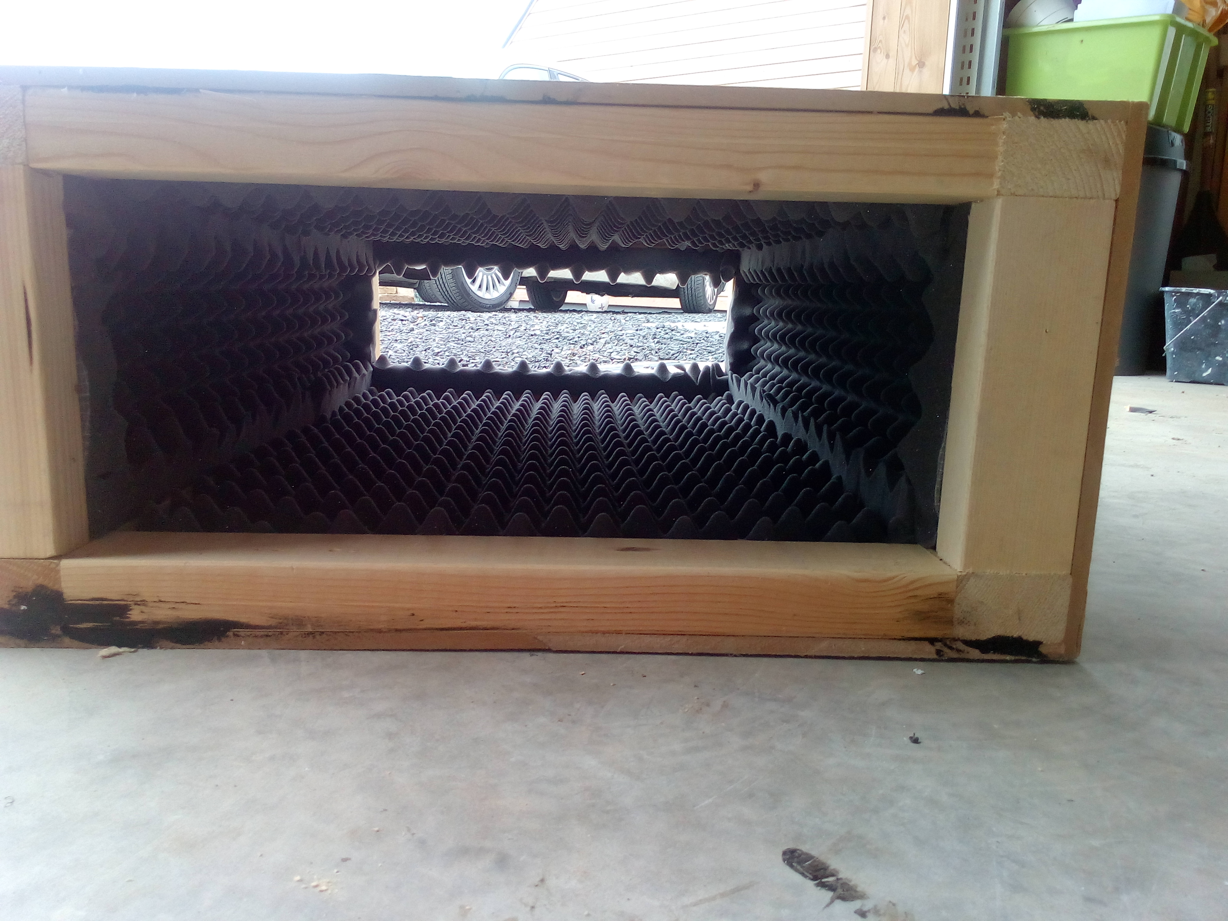
With an audience watching proceedings I set about constructing the box itself. 


IMG_20170615_120452.thumb.jpg.bcb8bced59402204c6f8576c5cb9cbd0.jpg


I decided on a rectangular shape, 900mm x 600mm x 300mm as this was about as big as I could make it without causing myself problems getting it into the loft next to the MVHR unit.


As you can see from the pictures, I constructed a fairly simple timber frame and clad it with MDF sheet.  Acoustic foam was stuck to the internal surfaces of the MDF, with additional strips of foam being added if any of the timber framing remained visible.


IMG_20170614_161106.thumb.jpg.de4093c20a568871e7626216e7adbc54.jpg


IMG_20170614_161231.thumb.jpg.265cb948db9b95ddf041ca69c89b25b2.jpg


IMG_20170615_131656.thumb.jpg.0c57103417a83415d0bfe6b2821bbf46.jpg


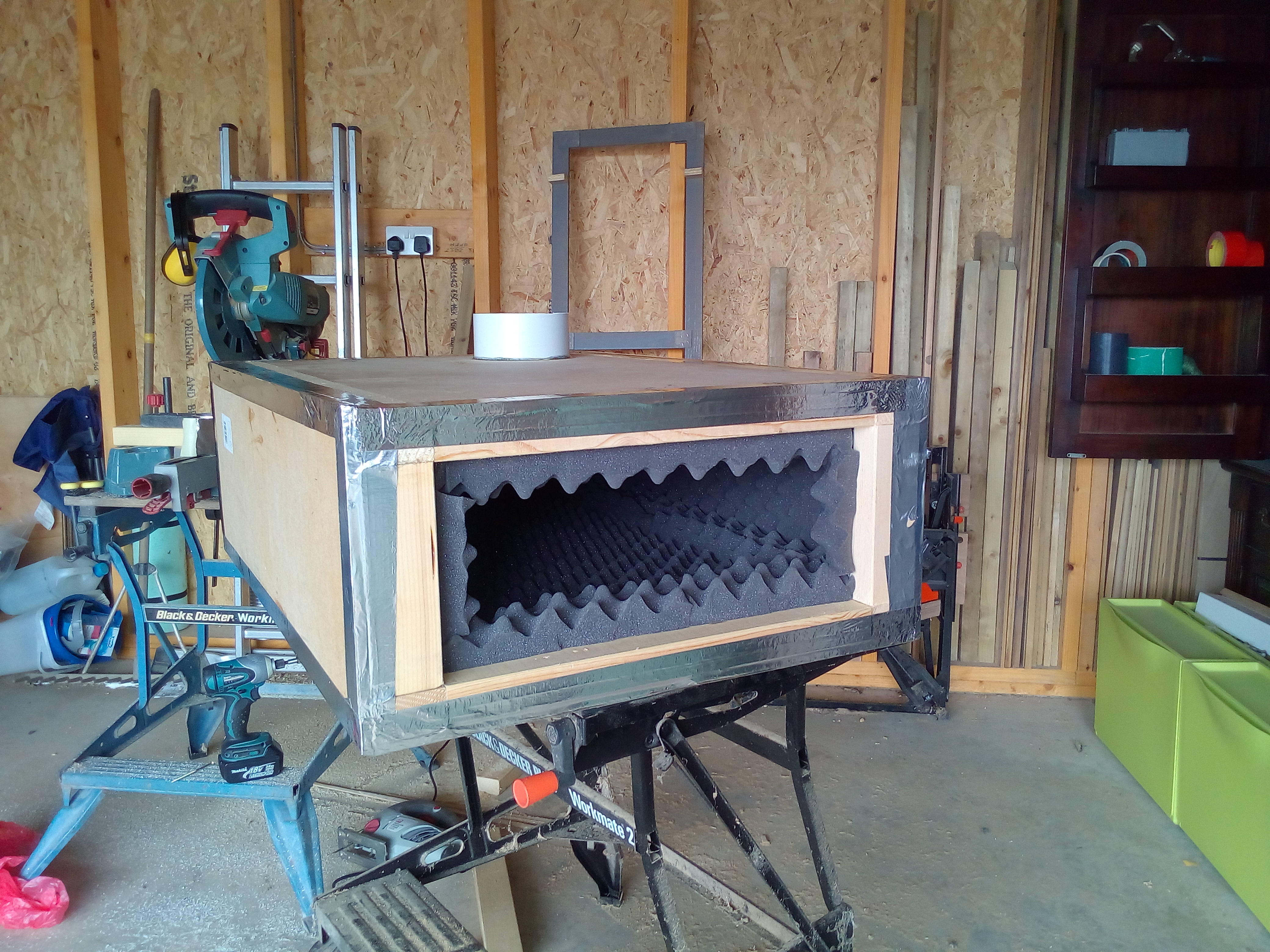
A generous bead of sealant seals the perimeter of every piece of MDF to the frame, and to all external MDF joints.  I then taped up all external joints as a belt and braces approach.  The end panel remains removable, as I used some foam tape as the sealing gasket rather than sealant.


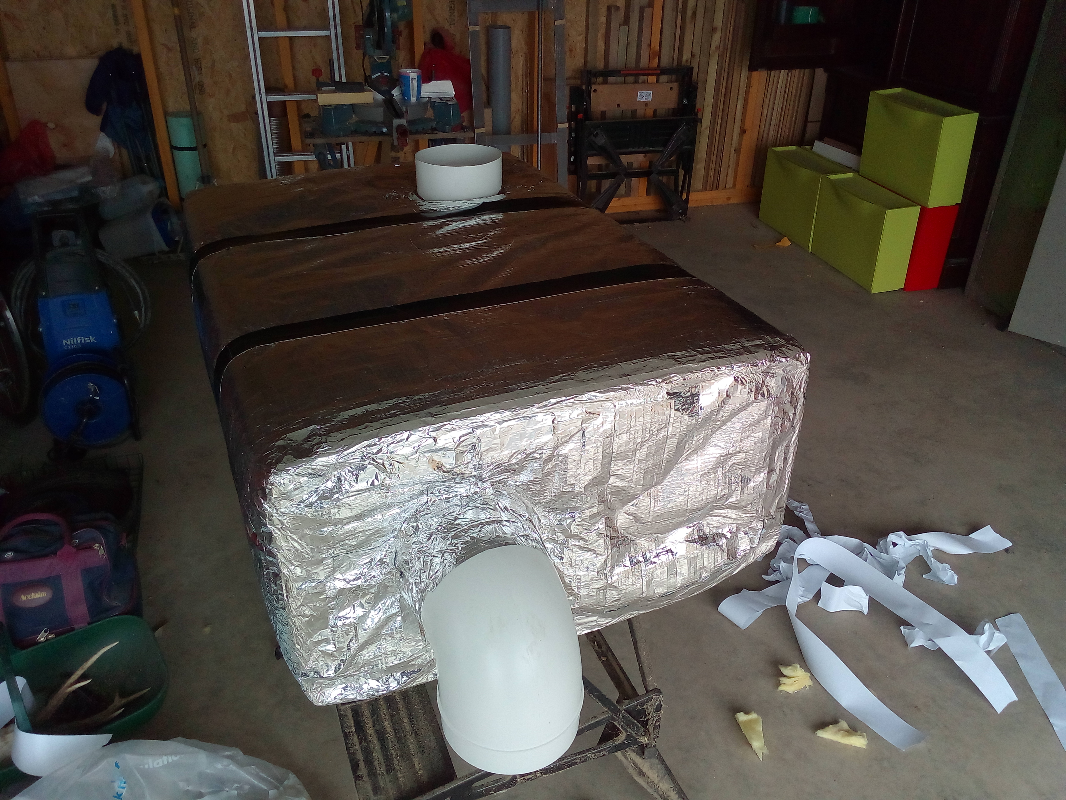
Using a jigsaw, I cut out 150mm holes in the top and end of the box and sealed in place short lengths of 150mm plastic duct, the idea being that these permanent connection points could then be fitted with whatever additional rigid or flexible ducting was required to make the final connections to the MVHR unit.  


IMG_20170615_133203.thumb.jpg.fa32da6c72a48f7754ae958c6dc4c0c3.jpg


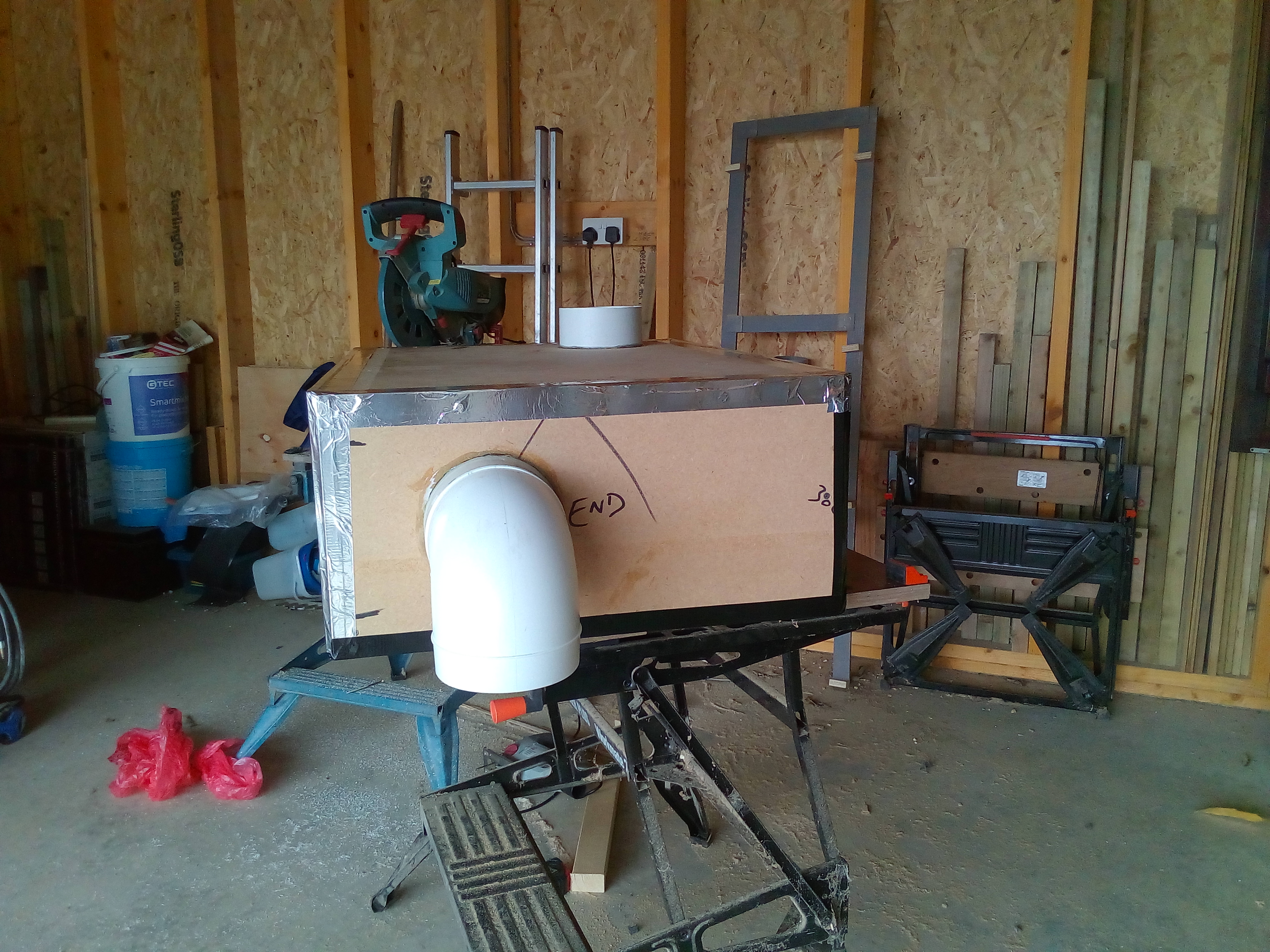
Cutting the plastic duct was a bit of a challenge due to the inherent flex in the pipe - it simply isn't as thick walled / strong as drain pipe.  After a couple of failed attempts at getting a straight cut, I switched to using my mitre saw. Holding the duct against the back upright guide on the saw, I simply brought the blade down for the first cut, then rotated the duct against the back plate until the blade had cut all the way round the duct.  This produced nice, clean straight cuts.


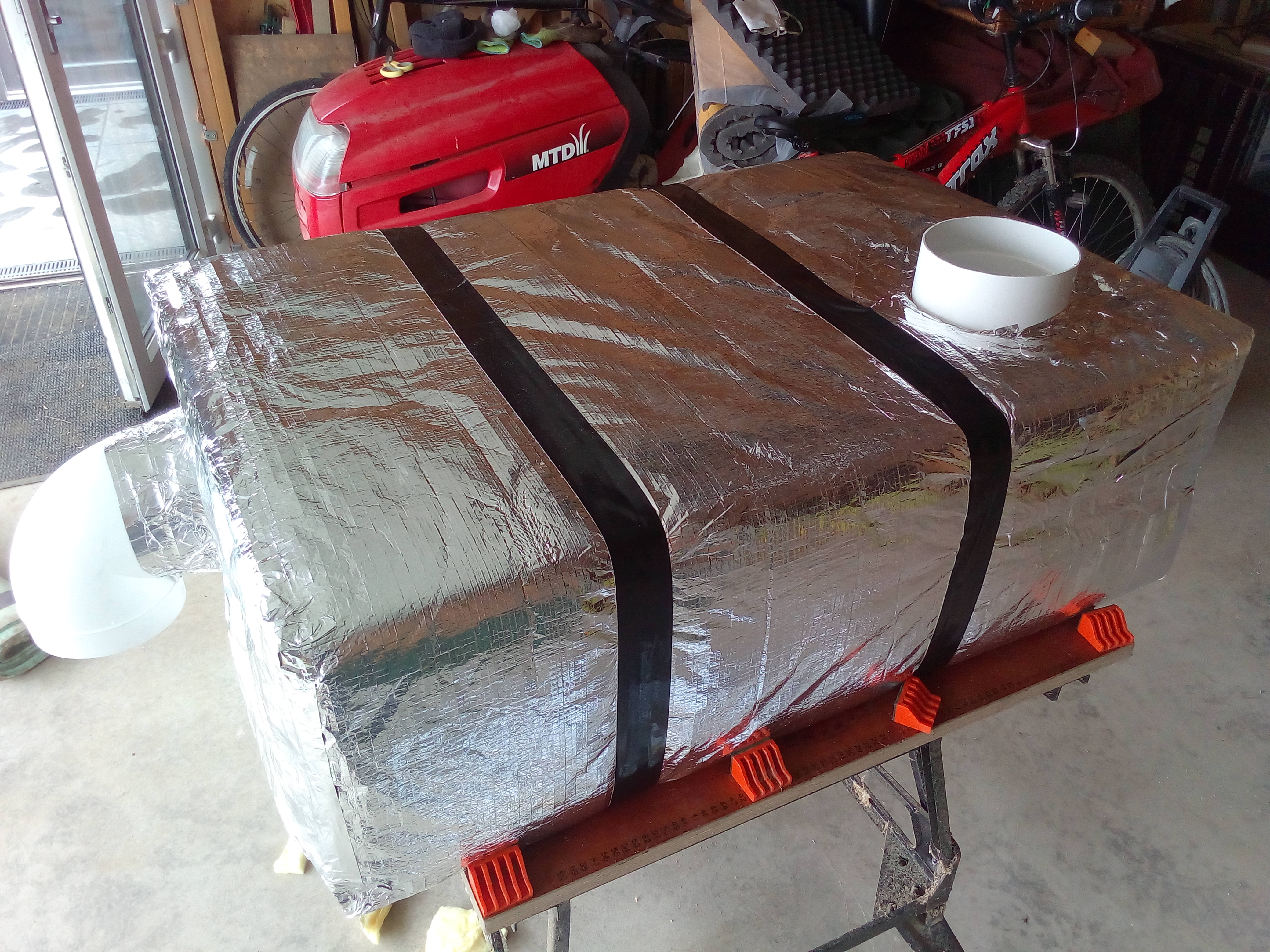
To finish, I wrapped the whole box in foil backed insulation and taped it all up. 


IMG_20170615_143542.thumb.jpg.e223f44b553179140c9ff07d1ed6b7b4.jpg


IMG_20170615_143551.thumb.jpg.a6a1c6aa436a33fcea922a17631bfaf3.jpg


Up into the loft, I fitted a couple of pieces of timber as a supporting platform for the silencer and positioned it next to the MVHR unit. Using a mix of flexible and rigid ducting, I made the final connections to the MVHR unit and supply manifold. 


IMG_20170616_120726.thumb.jpg.0c2480acce32be6b2d5135198b378ca2.jpg


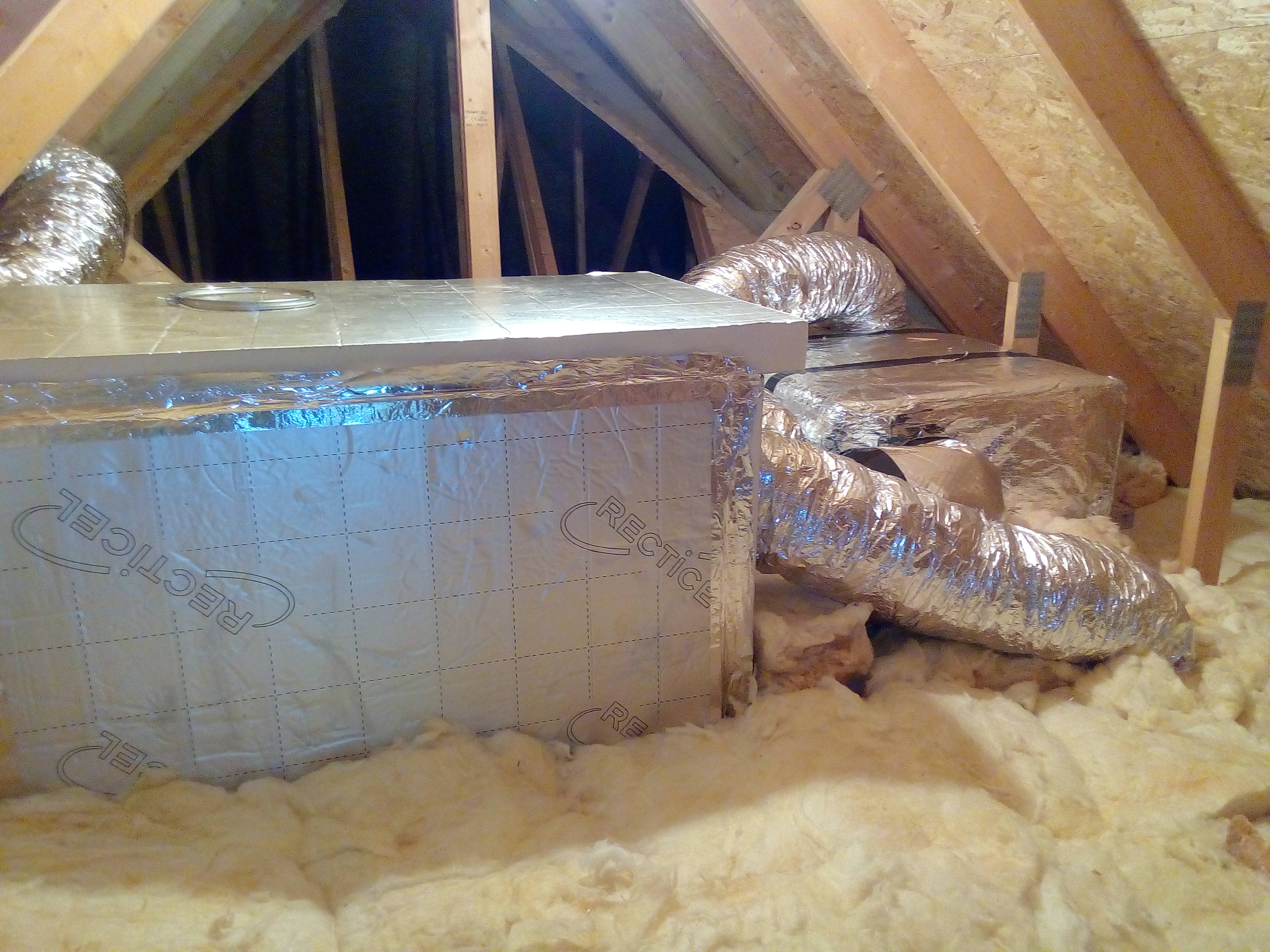
Having switched the unit back on, the difference was immediately noticeable. Even in the dead of night I cannot hear fan noise from any of the supply terminals, so it appears as if my home made silencer is doing its job, and doing it well. 


We still have fan noise being emitted from extraction terminals so I’ll be fitting a silencer on the extract duct as well.  The plan is to use the silencer BPC are sending me.  Whether it will be as effective given it’s far smaller size and therefore has a smaller sound absorption surface, remains to be seen.  I hope so, but if not, I do have enough material left to make another DIY (albeit smaller) silencer.


Next entry will be – Heating system and DHW


  • Like 4

15 Comments


Recommended Comments

The 'Recticel' panel on the front isn't foamed in place, reasonably snug fit and taped so can be dropped down to access the front of the MVHR unit / access the filters.


Ideally, I would have had the unit within the heated envelope, but changing the position of my DHW cylinder makes the previously identified space a bit tight.  I could still fit it in the service cupboard, but it would be quite a bit of effort now for very little gain. Despite it being in a cold space (albeit in an insulated box) heat recovery performance appears to be as per manufacturers claims so I'm happy enough.


I had thought about creating an insulated room in that part of the loft so I didn't have to box the MVHR and insulate visible ducting, but it was just another expense when I could achieve the same practical results using offcuts to box in the MVHR, and duct insulation I had anyway.

Link to comment

Hi Stone, 


@ProDave has a good point, you will need to maintain your unit and it must comply with CDM regulations. Is this the best solution your designer/installer came up with? If you do not maintain it, your home will become unhealthy. 


ryan


Link to comment
1 hour ago, Ryan4Healthy Home Movement said:

Hi Stone, 


@ProDave has a good point, you will need to maintain your unit and it must comply with CDM regulations. Is this the best solution your designer/installer came up with? If you do not maintain it, your home will become unhealthy. 


ryan


Nope, it just has to require to Part F (or the Scottish equivalent in this case).  There is a requirement in Part F to provide adequate access for regular maintenance, and that removable panel meets that requirement.


I undertook my own certification against Part F for our installation, as there is no requirement for the person commissioning a domestic MVHR to hold any certification, and the procedure for commissioning and providing the required information is in the additional information that applies to Part F (here in England and Wales, may well be different in Scotland).

Link to comment
10 hours ago, Ryan4Healthy Home Movement said:

Hi Stone, 


@ProDave has a good point, you will need to maintain your unit and it must comply with CDM regulations. Is this the best solution your designer/installer came up with? If you do not maintain it, your home will become unhealthy. 


ryan


As explained, the front panel made out of Recticel insulation is simply taped in place, so removable, thus letting me access the front of the MVHR unit.  From the front I can change the filters, remove the heat exchange, operate the control panel, access the wiring connections (if say, I want to add another sensor) and access the condensate drain point.  Access into that particular loft area is through a hatch from our mezzanine, so I enter the loft space at loft level - i.e. no ladder required.  Fair enough, the hatch into the loft space isn't a full size door, but that's a compromise I'm prepared to live with.  


Servicing / maintaining the MVHR unit in its current location really isn't an issue.

Link to comment

is there any way you can measure the power consumption? it would be interesting to know what the resultant (Specific Fan Power) SFP is after the silencers have been fitted.


Ryan


Link to comment

Very unlikely to change the SFP at all, as the flow dynamics are dominated by the throttling effect of the terminal/plenum restrictors, that are a couple of orders of magnitude greater.

Link to comment

Hi sorry,

was interested to see what the actual SFP was of the system..... to compare it with what the manufacture.


with regards to:

On 26/06/2017 at 20:10, JSHarris said:

Very unlikely to change the SFP at all, as the flow dynamics are dominated by the throttling effect of the terminal/plenum restrictors, that are a couple of orders of magnitude greater.


your system resistance is not all the resistance added up, its only the index run. The dampers are used for balance this resistance which should only have minor effect on the index run [the valve furthest from the MVHR unit.] (if balanced 100% correctly you don't need a restrictor on your index).  If you have throttled back your index run a lot that means you will have much more resistance than you need. The three biggest resistances are: noise attenuators (manufactured ones), external louvres and discharge terminal. which are all around 10- 30Pa each. Where as duct work is about 1 pa/m if sized correctly .... 


ryan


Link to comment

Every domestic MVHR system I've ever heard of uses flow restrictors to balance the airflow to each room, in order to comply with the provisions of Part F (specifically Table 5).  As such, the flow rate in the individual supply and extract ducts is set by the restrictors, either within the distribution plenums (the flow balancing system we have) or at the individual room terminals (a more common domestic balancing solution).


Dampers are not normally fitted to domestic systems, and cannot be fitted to the duct system that @Stones has, and that I and a few others have used.


What you seem to be describing is the sort of air handling system fitted to the last commercial project I managed, and they bear little resemblance to domestic-scale MVHR systems.


Finally, the impact of a very large cross sectional area absorption silencer plenum on the physics of airflow is pretty straightforward to assess for a domestic system like this.  As long as the CSA of the silencing plenum is greater than the CSA of the primary ducts to the distribution plenum chamber, and as long as the primary duct length is not significantly altered, the SFP cannot be reduced.  SFP may slightly improve, because of the attenuation of any fan-induced flow pulsations within the absorption silencing plenum, as a consequence of making the primary duct flow very slightly less turbulent at the silencer outlet, but this almost certainly isn't significant.

Link to comment

Bringing this thread back down to my "Luddite" level :)............


Does the number of bends in the ducting have any impact on performance?

In my revised plan (I think I've revised it 4 times already!) I'm going to have 3 90 degree bends in the air intake and outlet. 2 of them within 500mm of each other.


By the way the reason for the design change is that the bloody thing is HUGE and seriously heavy. I've got to rig up a block and tackle to get it upstairs. Its almost too heavy for two people to carry along the flat!


  • Like 1
Link to comment
7 minutes ago, Barney12 said:

Does the number of bends in the ducting have any impact on performance?


Yep.....


Any chance you can do 45 degree and not 90..? Go via a roof terminal ..?

Link to comment
8 minutes ago, Barney12 said:

Does the number of bends in the ducting have any impact on performance?

In my revised plan (I think I've revised it 4 times already!) I'm going to have 3 90 degree bends in the air intake and outlet. 2 of them within 500mm of each other.


By the way the reason for the design change is that the bloody thing is HUGE and seriously heavy. I've got to rig up a block and tackle to get it upstairs. Its almost too heavy for two people to carry along the flat!


Yes, every bend will increase flow resistance by a small amount, so the fewer the bends and the shallower the angle of them the better.


Having said that, it's often not possible to avoid 90 deg bends on the primary duct connections at all, unless there is a lot of space around the MVHR unit.  I've had to fit 90 deg bends on all four MVHR primary duct connections, as there was no way I could have run straight ducts or gentle bends to it, as there just wasn't the space available.  Having sharp bends in the big primary ducts has less impact than having them in the small distribution ducts that connect to the plenums.


I used a block and tackle to get our MVHR up the stairwell.  IIRC it weighed around 70kg.

Edited by JSHarris
Link to comment
56 minutes ago, PeterW said:


Yep.....


Any chance you can do 45 degree and not 90..? Go via a roof terminal ..?


There is absolutely no way I could use anything other than 90's out of the unit itself. 

I might be able to use 45's after that but I'll have to see. The space is way tighter than I had envisaged. 


The unit specification would suggest that it's capable of supplying a much bigger house than ours (300m2 vs 210m2) so I assume that's a help?

Link to comment
1 hour ago, Barney12 said:


There is absolutely no way I could use anything other than 90's out of the unit itself. 

I might be able to use 45's after that but I'll have to see. The space is way tighter than I had envisaged. 


The unit specification would suggest that it's capable of supplying a much bigger house than ours (300m2 vs 210m2) so I assume that's a help?


That's the situation we were in, so I opted for the slightly more capable unit, which was slightly bigger than we needed, to make sure we had a bit in reserve for the losses.  The higher airflow unit was the same physical size, and not a lot more expensive, so was as easy to fit in the space.


In practice, the measured flow rates from every terminal massively exceeded the requirements in Part F, so they all needed to be throttled down a lot, and we can exceed the background ventilation requirement on the lowest setting of the MVHR, which is around the highest SFP, too.


I'd not be overly worried about a couple of 90 deg bends, as they will be far less restrictive then the very flexible duct that's often used.  I used some semi-flexible "concertina" type aluminium duct for the vibration decoupling sections, wrapped with insulation on the external inlet/outlet side, and that seems less restrictive than the more floppy stuff.

  • Like 1
Link to comment

We likewise went for a larger MVHR unit to ensure it had enough capacity to be run at a relatively low fan speed. With the Vent Asia, it's also possible to set the fan speeds for the main operational settings (Low, Normal, Boost).


I've used some rigid 90 degree bends connecting up the MVHR unit to inside and outside, as I felt this was better for air flow vs flexible duct bent to the same degree. 

Link to comment

Create an account or sign in to comment

You need to be a member in order to leave a comment

Create an account

Sign up for a new account in our community. It's easy!

Register a new account

Sign in

Already have an account? Sign in here.

Sign In Now
×
×
  • Create New...