Bruno
-
Posts
87 -
Joined
-
Last visited
Everything posted by Bruno
-
Just something which I think was not referred by anyone. Is your buffer tank connected "in series" with the heating circuit, or is your ASHP heating the buffer tank and then another water circuit goes to the UFH/rads (with another circulating pump)?
-
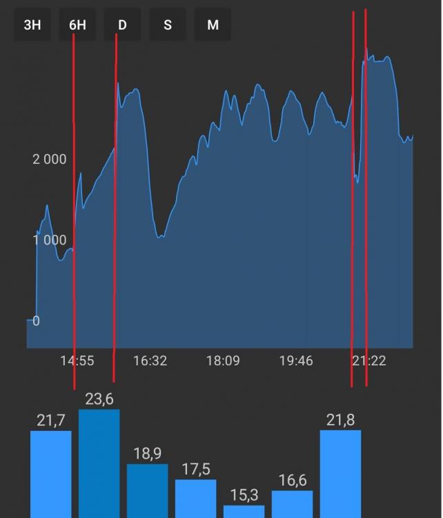
Wow, 0,65? That's really a low, low curve. It gives you under 40ºC flow temperature at 0º outside. Dang ? Actually this temperature curve is what's making me really confuse. As I said, I run the AHSP mostly during the day+1st hours of the evening. Now we are having some colder days but very sunny. So during the day we have some 14-17º. As soon as the sun goes away it drops fast to 7-8º and lower during the evening. Even if my curve is at 2.0, according to the graph the target flow temperature is under 40º during the day, so the consumption is low but the house doesn't heat (setpoint 21,5 - room temperature eg. 18,5º). Only when the sun goes away and the outside temperature drops, then the flow temperature rises and the house gets comfy. Here is yesterday's consumption graph, it's clear that the consumption rises greatly when the night falls. I would rather having it opposite, because a) higher outside temperature means higher COP b) when we return from work we would like to have it warmer already AND the >3,3kW that the HP is consuming sometimes force us to manage other electric devices which we might need to use. When we are not at home, then the AHSP can use whatever energy it requires. The area between the red lines is DHW. I might consider testing it working 24/7, but if I'm thinking this correctly, it will just shut off during the day (which, for radiators, is even worse).
-
The set-back temperature is very low, 12ºC or something like that. As I said, I want it to shut down outside the programmed heating hours ? Regarding the circulation pump you might have a point there. I reduced its speed because of that noise I mentioned, but I can increase it again and compare. Another thing I can try is to reduce the curve, as far as I could check the buffer temperature is stable enough but the consumption oscillates quite a bit, maybe it's overshooting. But I need colder days to test it properly, now it's just too easy for the HP ?
-
I can't really understand why. It's exactly the same setup, just changed a 8 to a 10. Rads heat up nicely, the temperature finally gets to the setpoint, don't know, the behaviour looks better now. There has to be something different inside the controller. Anyway today was again a not-very-cold day so the consumption curve is very pleasant. I'll keep following up
-
The difference I noticed in the consumption is that now the heat pump goes to max power for a long time, until the temperature in the room gets close to the setpoint, then it starts to modulate. Before, it started with max power for a few minutes, then abruptly dropped the consumption and kept working in a lower power, increasing the power and the flow temperature as the temperature outside decreases. The target temperature was hardly reached unless the day wasn't too cold. I have some consumption graphs which I can show when I get to the computer. The installation is the same (the buffer was there already, I just changed the parameters) I'm running the heat pump from 13h until 22h30, with 2 DHW cycles in between (30-40min each).
-
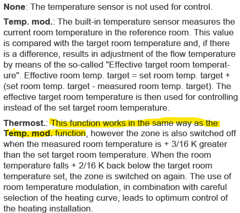
Yes, that's what I tought it would do. Thanks Actually that's not what the documentation says. The documentation says that termostat will work as "temp mod", except that if the temperature in the room exceeds the setpoint the system will shut down. That's actually a good thing for me as I'm using the "night" mode to turn the heat pump off (noise in the building as explained here). Yeah... That would actually be great, but I don't think my house can go with a curve of 1.1. At least from my experience in the last 2 months of using the heat pump. However... I've been monitoring the consumption after I changed the basic diagram from 8 to 10. The consumption for now it's crazy high (just turned on 2h ago) but it's for sure different than it was before. I will keep you informed, but for sure something *is* different just by changing the basic diagram from 8 to 10.
-
I know, but it almost never reaches that. Usually it works at 45-55º. 40º is also low and of course, 15º is cold ? The heat curve is configured at 2.0 after I messed around with that for a while. There was no MCS certificate, I'm not from the UK so we don't have that. Unfortunately the installer's knowledge doesn't seem to be bigger than mine, so I'm trying to figure out the best configurations. Could you please ellaborate? The description in the manual seems to relate to the minimum and maximum flow temperature. And no other controllers, I only have the VRC700 (and the internet gateway, but that doesn't count :-)) It is. And yes, there is an external temperature sensor. Nevertheless it's also mis-positioned as it gets direct sunlight so in sunny days the reading is too high...
-
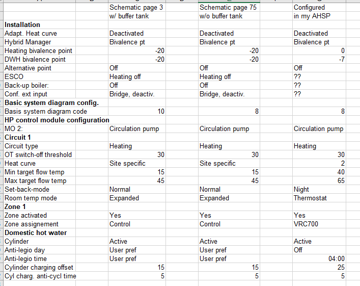
Thank you for your reply. Well, I have a question about the heat pump's behavior which I will detail in another topic. However, when I was gathering information about that issue I revisited the manual I linked above. I then noticed that my "basic diagram" is configured as 8, but that is the case when there is no buffer tank, which I do have. Then I noticed the 40l "decoupler", but my buffer tank is actually 100l. So the heat pump "thinks" it's connected directly to the radiator's circuit, but there is a big water volume in the middle, much bigger than the volume of water in the rads. Pretty much all other configurations are according to the recommended values (except for min/max flow temperature because the default values are too low for aluminium radiators). I made the following table, some parameters I could not find Meanwhile I already connected the VF1 sensor and changed the basic diagram to 10 and I will follow the consumption/heating pattern during the day, see if there is some difference.
-
And mis-installed too? I have an aroTHERM plus installed with a configuration really close to Vaillant's 1st schematic in this document: Heat pump + buffer tank + radiators + DWH https://www.vaillant.co.uk/downloads/aproducts/renewables-1/arotherm-plus/all-schematics-wiring-notes-1799366.pdf (pages 3-5) The difference is that the buffer tank (Vaillant calls it "decoupler") is 100l instead of the 40l in the schematics. Unfortunately that seems to be a rule of thumb here, more or less 10l/kW and there it is... Does anyone know what can this cause in the equipment's behavior? Is it just a waste of water mass or will it impact it negatively? However... Looking at the configuration and connections, the equipment is configured as if it didn't have any buffer tank (schematics on page 75-77) Also for this reason the temperature sensor in the buffer tank is installed but not connected anywhere. So I clearly need to fix the parametrization as well. Toughts? Thanks
-
ASHP installed together with existing heating system
Bruno replied to Bruno's topic in Air Source Heat Pumps (ASHP)
So a little update about this. Not me or the installer can get any references for these flexible hoses. Meanwhile I was able to get in touch with Vaillant Portugal. I explained the problem with the noise/vibrations and asked them about these flexible hoses: why does aroTHERM plus has only a short flexible connection, while the "older" aroTHERM mentions clearly the >0,75m flexible connection. To my big surprise, they said that the current connection is fine and that these flexible hoses should not be necessary at all. Thoughts? -
ASHP installed together with existing heating system
Bruno replied to Bruno's topic in Air Source Heat Pumps (ASHP)
Still looking into the flexible pipes, I need your help again. The flexible pipes shown in Vaillant installation videos for aroTHERM plus are just small connectors, nothing big. There is even an accessory kit which includes these connectors. Older arotherm manuals do mention a >0,75m flexible connection. The installer said that he cannot get these components (the flexible hoses/pipes) from Vaillant. Also, should I aim for the big pipes like in the older manuals, or the smaller ones as in recent documentation? Does anyone has a link for the 1 1/4" flexible hoses with 1 1/4" connection to the heat pump? On the wall we have 32mm pipes. -
ASHP installed together with existing heating system
Bruno replied to Bruno's topic in Air Source Heat Pumps (ASHP)
I did see that as well. The installer said that these are to be inside the house as someone could go and close them. Not a big deal there, just a few more liters of water to waste. And of course, to refill the heat pump and part of the circuit. I will install the flexible pipes for sure, then I'll install the rubber pads at the same time. -
ASHP installed together with existing heating system
Bruno replied to Bruno's topic in Air Source Heat Pumps (ASHP)
No, there aren't. From the outside unit there are only pipes to the inside. All isolating valves are on the inside. -
ASHP installed together with existing heating system
Bruno replied to Bruno's topic in Air Source Heat Pumps (ASHP)
On the inside I was already considering to insulate all pipes. I used in the past (previous plumbing from the wood burner) a kind of cardboard "pipe" filled with rock wool (sorry not sure if this is the correct term) around the pipes. That works very well, as I tested with a thermal camera before and after and the temperature around the pipes was greatly reduced. I'll post a picture later once I get to my archive It's on the outside that I'm a bit lost, I have no idea what to use and how, in order to insulate and also to resist the weather. Will do for sure. Thank you -
ASHP installed together with existing heating system
Bruno replied to Bruno's topic in Air Source Heat Pumps (ASHP)
Going back to this, and using the picture I posted previously as a reference, I am not sure that I can lift the unit 20mm without extending the pipes. I just arrived home and went looking into that with more caution. I already have the rubber pads but I will wait for the installer to come and do that. I'm afraid that the "corners" which connect the pipes might get too much tension and break. That would be a real problem and I wouldn't be able to fix it myself. -
ASHP installed together with existing heating system
Bruno replied to Bruno's topic in Air Source Heat Pumps (ASHP)
Yes, that was already installed with the DHW tank back when the original heating system (with the wood burner) was installed -
ASHP installed together with existing heating system
Bruno replied to Bruno's topic in Air Source Heat Pumps (ASHP)
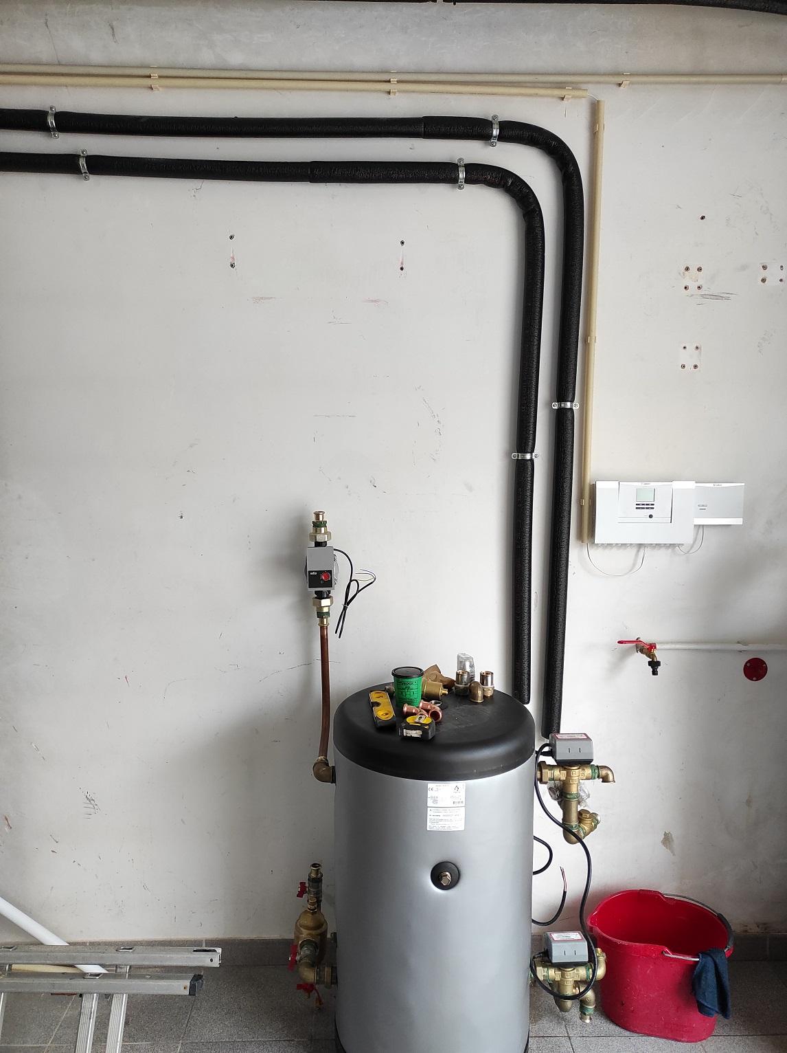
Yes, it is. Thank you, I actually have access to these rubber pads for free ? Will try them shortly. No, there aren't. It's just 3 sets of 90º curved sections. Here's a picture which shows both the tubing and the wall mounting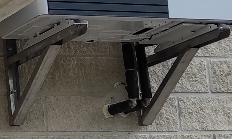
-
ASHP installed together with existing heating system
Bruno replied to Bruno's topic in Air Source Heat Pumps (ASHP)
Any thoughts about these issues? Thanks -
My Vaillant aroTHERM Plus also produces a lot of condensation. Mine is hanged on the wall and for now it's just dripping to the floor. But I also have to find a better way for that.
-
ASHP installed together with existing heating system
Bruno replied to Bruno's topic in Air Source Heat Pumps (ASHP)
I need some further advice on 2 issues, both related to the installation. - insulation of the pipes and connections. Although the installer was very careful in distributing the pipes on the wall to reduce "dead space", I'm a bit concerned about insulation. All pipes have an external insulation sleeve, which is the same on the inside and outside. But all connection parts (especially 90º metallic - brass? - curves) are not insulated at all. Outside, there are 2 of these curves. Inside, around the 3-way valves there is big "set" of metallic parts which are all exposed and do heat up a lot when the heat pump is working. Isn't this something which might represent significant heat losses especially in winter? Do you have any recommendation for better insulation, or shouldn't I be worried? I did ask the installer about this, he claims that this is the standard way of doing it. - vibration noises in the structure The heat pump was mounted on the wall as I cannot put it on the ground. During the night when everything is silent there is an audible humming noise which seems to come from the structure of the house. Although this seems to be a frequent problem, it's something that never came up in all the previous reading and research I did. The solutions I found out now are some rubber pads, but I would like to ask if someone already encountered this issue and which kind of pads are the safest bet in fixing this problem? I discussed this with the installer, we will go ahead and do a first test with a small rubber piece just to check if there is some improvement. -
ASHP installed together with existing heating system
Bruno replied to Bruno's topic in Air Source Heat Pumps (ASHP)
Yes, the hydraulic unit is an "all in one" solution from Vaillant. It's integrated and uses the Ebus as well. The heat exchanger is also called hydraulic separator. On the first page of this topic someone explained it very well. But basically it's a plate exchanger which transfers heat from one or more circuit to another. As for Glycol it's a corrosion inhibitor which should always be used in combination with aluminium radiators. It also affects the freezing (or was it boiling?...) point of the water, which is why it's only used on the "inside" portion of the circuit: you don't want water with Glycol running through the heat pump Edit: again, this is what I've been told -
ASHP installed together with existing heating system
Bruno replied to Bruno's topic in Air Source Heat Pumps (ASHP)
Here's a picture taken during installation. Sorry about the mess :) You can see the buffer tank, the 2 3-way valves (on the right of the tank) and the circulating pump (on the left). Further on the right there's the Vaillant controller which receives the temperature probes and feeds the valves and circulating pump. It's not on the picture but to the right of all that there's the DWH cylinder.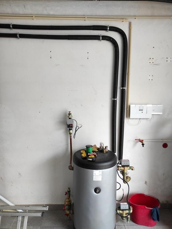
-
ASHP installed together with existing heating system
Bruno replied to Bruno's topic in Air Source Heat Pumps (ASHP)
Nope, standard "after market" buffer tank. 100l as we couldn't get an affordable smaller one. Yes Yes to both For what I've been told, it serves to couple different heat sources together (eg heat pump and solar), with much less amount of water (therefore inertia) compared to a buffer tank. It also isolates the ASHP from the heating circuit so that you don't have to empty all the circuit (thus spending Glycol and lots of water) every time you need to do maintenance. But the buffer tank also does that. That's actually messy. According to Vaillant, you need a buffer tank to perform defrost. When the heat pump needs do defrost it will fetch heat from the buffer tank so that's why it needs it. In the installation manual it mentions different buffer capacity according to the heating circuit temperature: lower temperature --> bigger buffer, higher temperature --> smaller buffer. It can be as small as 20l IIRC. Nevertheless, pretty much all installers here use the buffer tank (in Portugal defrost is not really a thing ?) as a way to stabilize the temperature fluctuations in the heating circuit: it's actually called an "inertia tank" and not "buffer tank" and the thumb rule is 10l per kW. I'm guessing that most heat pumps are very oversized (I got quotations for 15kW units!), therefore the additional mass of water helps to stabilize the temperature in the circuit as a way to preven short cycling. From the little I observed the aroTHERM working I'm pretty sure that it would be able to run my central heating without any buffer at all (but I'm just guessing though). But I have a neighbour with a 14kW LG and no buffer (also no DWH just CH) and that pump is always, always short cycling. I'm pretty sure that it's extremely oversized so the buffer tank would help greatly. Also, the aroTHERM allows you to adjust the heating curve and the LG Therma V doesn't. In my short tests that parameter greatly influences the slope of the power output of the heat pump, in his case the LG pump starts and a few minutes later is at its maximum power, which is also not good for the short cycling issue. -
ASHP installed together with existing heating system
Bruno replied to Bruno's topic in Air Source Heat Pumps (ASHP)
First one, buffer only My first real complaint, the display always shows setpoint and actual heating temperature, even if heating is disabled as it is now. I'd like to show easily the DHW temperature, but it's only buried in the technician menus. Other than that, a quick test shows that my radiators do heat up nicely (energy consumption will be checked only next winter). Also the DHW is amazing. 1,5kWh from the grid to heat the tank in 45min. Before with the resistor it would take at least 5h and some 6kWh. I did choose a favourable hour of the day (14h so better COP). The tank should lose some temperature until it's time for shower, but I programmed it for a little boost after dinner time. -
ASHP installed together with existing heating system
Bruno replied to Bruno's topic in Air Source Heat Pumps (ASHP)
Yes, mine is a 8,5kW unit. I can get you the correct model tomorrow if you want. No, I don't have the hydraulic module. I have a 3-way valve for diverting the pump output to DHW tank/buffer tank + radiators. These are all "non Vaillant" components. The controls are all Vaillant: first is the "base" controller which receives the temperature probes, controls the circulating pump and 3-way valves, and also includes a wireless EBUS module which allows the usage of an external temperature and humidity sensor. Then the VRC700 controller which serves also as room temperature sensor.