Ultima357
-
Posts
113 -
Joined
-
Last visited
Everything posted by Ultima357
-
Basic ASHP Efficiency Questions
Ultima357 replied to soapstar's topic in Air Source Heat Pumps (ASHP)
If you have Heatmiser Neostats, simply set the overnight to 5 deg lower than daytime. Even in a poorly insulated place you'd be unlikely to drop this much. I'm guessing that as you have ASHP then you are decently insulated and draught proof. Not heating some of the house as high as the rest will save some pennies but if your internal walls are not insulated, a cold one could attract moisture if the temperature in these is too low. The cost difference between 10 and 15 deg is not huge and bear in mind that insurance policies usually have a minimum temperature required around the 13 to 15 mark if you're claiming for frozen pipes. -
Planned ASHP 1930s semi retrofit - experiences please?
Ultima357 replied to Greenbot's topic in Air Source Heat Pumps (ASHP)
On the PV front, in winter it obviously generates less and as the ASHP will be running, you are unlikely to get much input to the immersion. Summertime yes and plenty of it if you have a decent PV array facing south. You haven't said what your EPC score is and that should come with an estimated heat load if you got a full one. Size of the property is a factor too but I think that ASHP will be an expensive option for heating. I'm running one in a new build passively insulated home (3 to 400mm insulation and triple glazed, mvhr etc), 253m2 and it's rated at 12kw. It copes even in the recent freezing conditions but they all ice up and COP is circa 2 at freezing fog temperatures. My EPC score is A98. Good luck. PS See the Cost of Electricity thread elsewhere on ASHP running costs in a renovated property. -
Cost of Electricity
Ultima357 replied to canalsiderenovation's topic in Air Source Heat Pumps (ASHP)
According to the manual I found online, the display should have AR displayed to indicate remote air sensor or FR for floor sensor. If your bathroom one has just A then its on its own sensor and wrong. To change press M for 3 seconds and then use arrows to change and tick to accept. CS17-touchscreen-programmable-thermostat-Installation-guide.pdf -
Cost of Electricity
Ultima357 replied to canalsiderenovation's topic in Air Source Heat Pumps (ASHP)
Don't know what stats you have but my bathroom ones have the head outside and the sensor inside. The stat has to be set to monitor the remote sensor as they default to internal sensor. All three of mine were not properly set up by the installer. -
Cost of Electricity
Ultima357 replied to canalsiderenovation's topic in Air Source Heat Pumps (ASHP)
Yes they modulate fully. Anywhere from around 1kw to the maximum. In my experience it'll pull up to 4kw (possibly a little more) when hitting the higher temps for water heating and close to this for UFH. Just judging by the figures on the smart meter gizzmo and deducting our normal run rate of 4-500w. -
Calling all owners of Samsung Gen6 ASHP (maybe others too). I have found on my system that when the exterior temperature drops to 2deg or below, if the pump is not working for heat/DHW, it enters a frost prevention programme where it runs the main circulation pump and operates the DHW valve. This means it is sucking heat out of your hot water tank to prevent the external unit getting the shivers. Quite why is the good question when mine and I suspect everyone's is filled with antifreeze protector. We've posed the query via our contractor to Samsung as the contractor is as puzzled as I am as to why it should do it. I discovered this by accident as I set the internal overnight temps back a degree or so at 22:00. One frosty night walking past the kit cupboard at 24:00ish I heard the circulation pump running and discovered this. On a fully cold night it takes around 8 to 10 degrees # out of the hot water tank (400l). I've now bypassed the DHW valve with a switch so it pulls it out of the buffer instead whilst we wait for Samsung to reply. Note the pump runs several times a night for around 5 mins a time. #We're passive insulated and EPC A, so room temps barely fall a degree overnight. It seems mad to me to have this put in the programme with no way to adjust it. If it could be set to only do when say the outside temperature falls towards the freeze point of your mix then fine, but otherwise this is just wasting heat.
-
I have 14 individual zones, so very controllable. We run at 22 to 23 degrees during the day and set back to 21 overnight. Like you, I find UFH not very responsive but then again mine is cast into the fully insulated floor slab, so 155 tons of concrete heat store and generally the pipes are in the middle of 150mm thick slab. So I guess it can't be that responsive. We rarely lose more than 1 degree overnight (22:00 to 07:00),so guess its not going to make a huge difference.
-
Do you think its better to run it 24hrs rather than as I do, which is to leave on but set it back a degree or two at night? With our passive construction, it doesn't come on at night. In the morning I bring in the zones as needed over a couple of hours or so, so that it doesn't suddenly get a huge heat demand.
-
Another new member and ASHP in Somerset
Ultima357 replied to Chris Bottomley's topic in Introduce Yourself
Yes I guess so, but 12kw still seems low. His space heating requirements are 4 times higher than mine which OK, can just mean it'll run 4 times longer, but it'll all depend on the actual heat load that they should have calculated given whatever u values they now have. Flowing at 20l/min which seems to be a common need for ashp, 12kw only raises it by 5deg above input temp, so if whole house demand is high, it might struggle to warm up enough. As I have a lot of UFH loops, (nearly 1.5km), when more than half are active it drops the temperature achieved at ashp outlet. -
Ah, yes forgotten about those, but they are quite pricey? Guess it depends on how many you plan on using.
-
Another new member and ASHP in Somerset
Ultima357 replied to Chris Bottomley's topic in Introduce Yourself
Are you sure that ASHP is large enough to cope? Taking out a 28kw oil boiler and replacing with just 12kw doesn't sound quite right to me. Did they do a heating load requirement for your house? I've got a 12kw Samsung ASHP in 253m2 passive house (new build) but our total heat load is just 7kw. -
If screwing down, then screw immediately adjacent to the nails. This should ensure you miss any pipes and cables as chippies usually give them a decent gap. If there's still a little movement and the nails squeak, a good squirt of WD40 can help cure and/or centre punch the nail down a tad. If it's chipboard and it's bouncing, it can be better to predrill same as screw size so the screw pulls the chipboard down rather than bitting into it. Like previously mentioned, it should really be glued too. My old house used to drive me nuts upstairs but of course the worst squeaks were where the central heating pipes were underneath it and way too dangerous to consider banging in an extra screw or two. New house is single storey, power floated concrete.... Silence at last!
-
Heatmiser Neostat v2 temperature sensor problem
Ultima357 replied to Ultima357's topic in Underfloor Heating
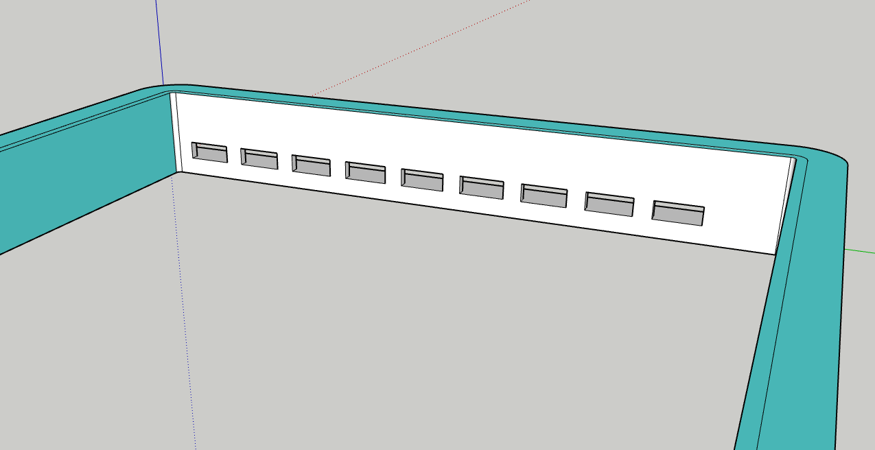
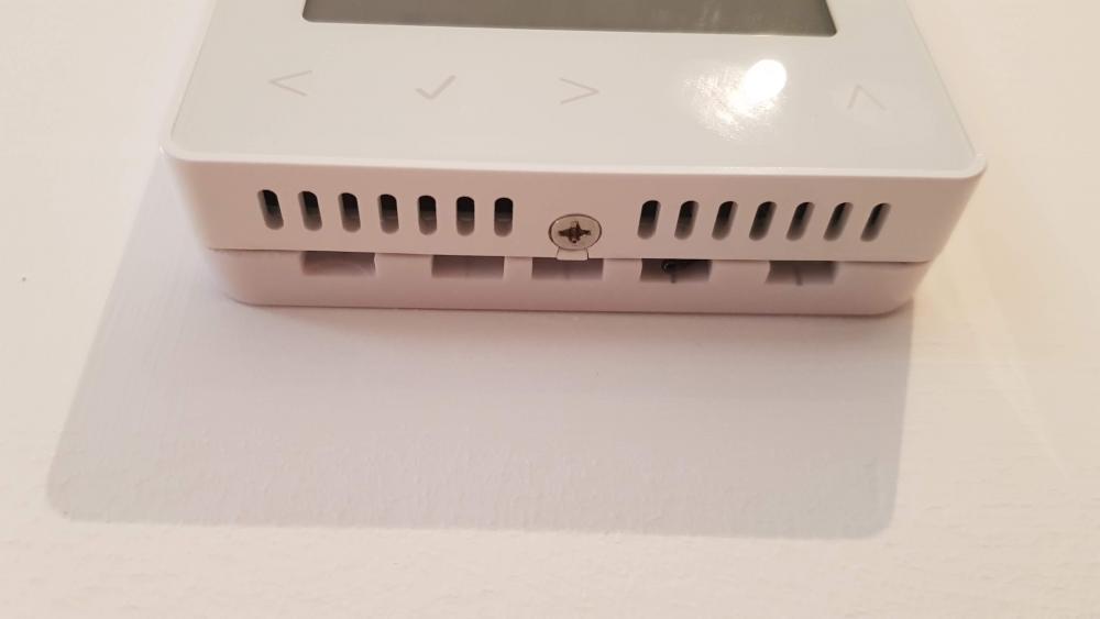
Now done all 11 (3 had remote sensors so not affected), recalibrated them and I now have much more stable temperature control, so very pleased with the result. As previously said, I measured the temperate of the top slot probing into the back. 29 degrees! Have sent a new design to Heatmiser. Given the large cost of tooling, I wouldn't expect them to jump on it though. Of course the slots would be on three sides, I just showed them how it could be disguised.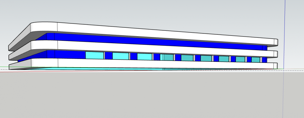

- 150 replies
-
- 4
-

-
- neostat
- temperature
- (and 1 more)
-
Heatmiser Neostat v2 temperature sensor problem
Ultima357 replied to Ultima357's topic in Underfloor Heating
Probably not a worry as its vented to rear of the plate which is all sealed in any case. It would be more difficult machining it on my router table at an angle too. Easy enough as a straight vent, but delicate and careful approach needed. We do have MVHR but you still get dust. The man who invents something that does away with dust will become a very rich man?. -
Heatmiser Neostat v2 temperature sensor problem
Ultima357 replied to Ultima357's topic in Underfloor Heating
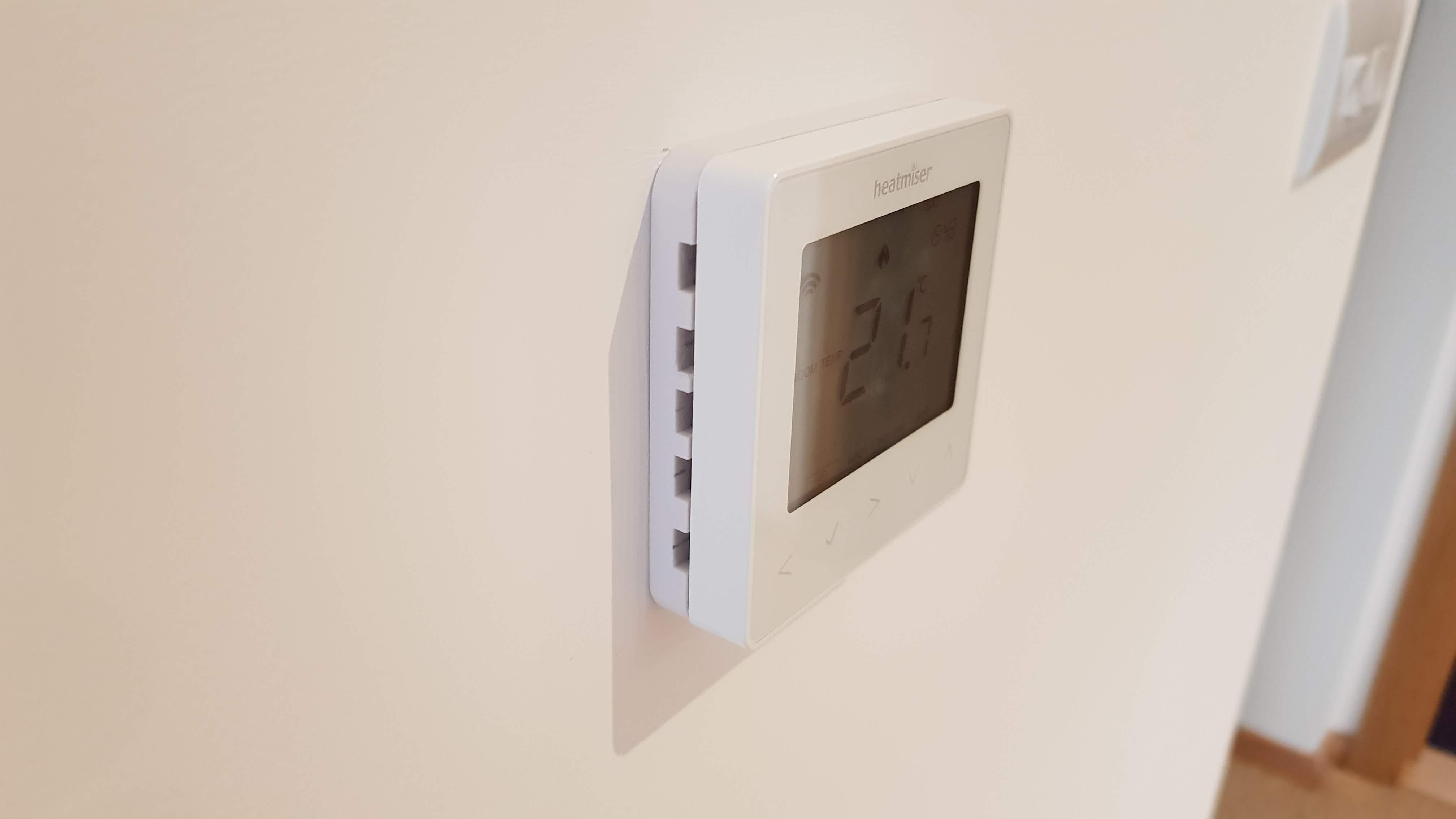
Definitely is the transformer. When you pull the back plate forward to fit my spacers, it's a nice warm handful. Guess around 30 to 32 deg. When I get the next spacers, I'll measure one. Decided to go with slots to the wall in the end, it doesn't seem to make any difference and is more pleasing aesthetically.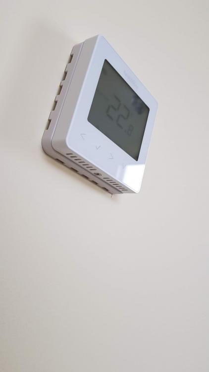
- 150 replies
-
- 2
-
-
- neostat
- temperature
- (and 1 more)
-
Heatmiser Neostat v2 temperature sensor problem
Ultima357 replied to Ultima357's topic in Underfloor Heating
As I read today. "It's relatively easy in physics to measure something. The hard part is knowing how accurately you are measuring it" Just about sums this saga up. Will buy some more spacers and get on with retrofitting them to the other stats now. They're just 97p each from Screwfix if you buy 3 plus. Search for single gang spacer.- 150 replies
-
- 1
-
-
- neostat
- temperature
- (and 1 more)
-
Heatmiser Neostat v2 temperature sensor problem
Ultima357 replied to Ultima357's topic in Underfloor Heating
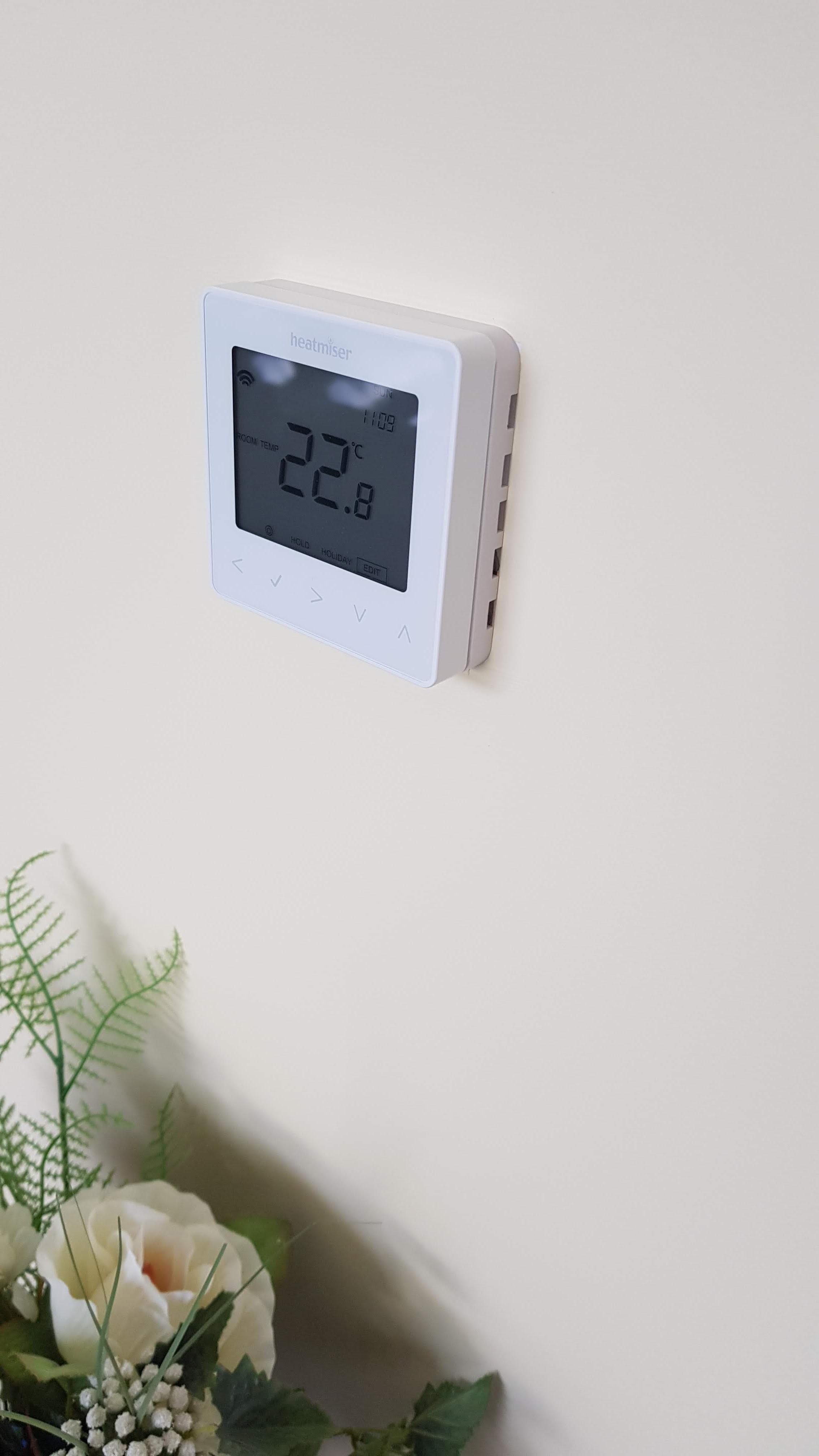
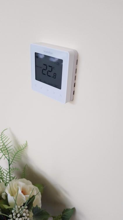
I've put in a remote one as a test, but both this and the inbuilt one read equally well now. My back boxes are metal but it clearly shows the problem of the heat generated by the psu. Yes, the battery wireless operated ones don't have this issue but they do have the flaw of the battery. A couple of years ago we went on holiday for a few weeks (when I had such a system in the old house) in the autumn and in the last week on our hols, the battery died. So instead of coming home to a nice warmed house, we arrived to a cold one. Not good! Will be speaking to the Heatmiser developer next week. -
Heatmiser Neostat v2 temperature sensor problem
Ultima357 replied to Ultima357's topic in Underfloor Heating
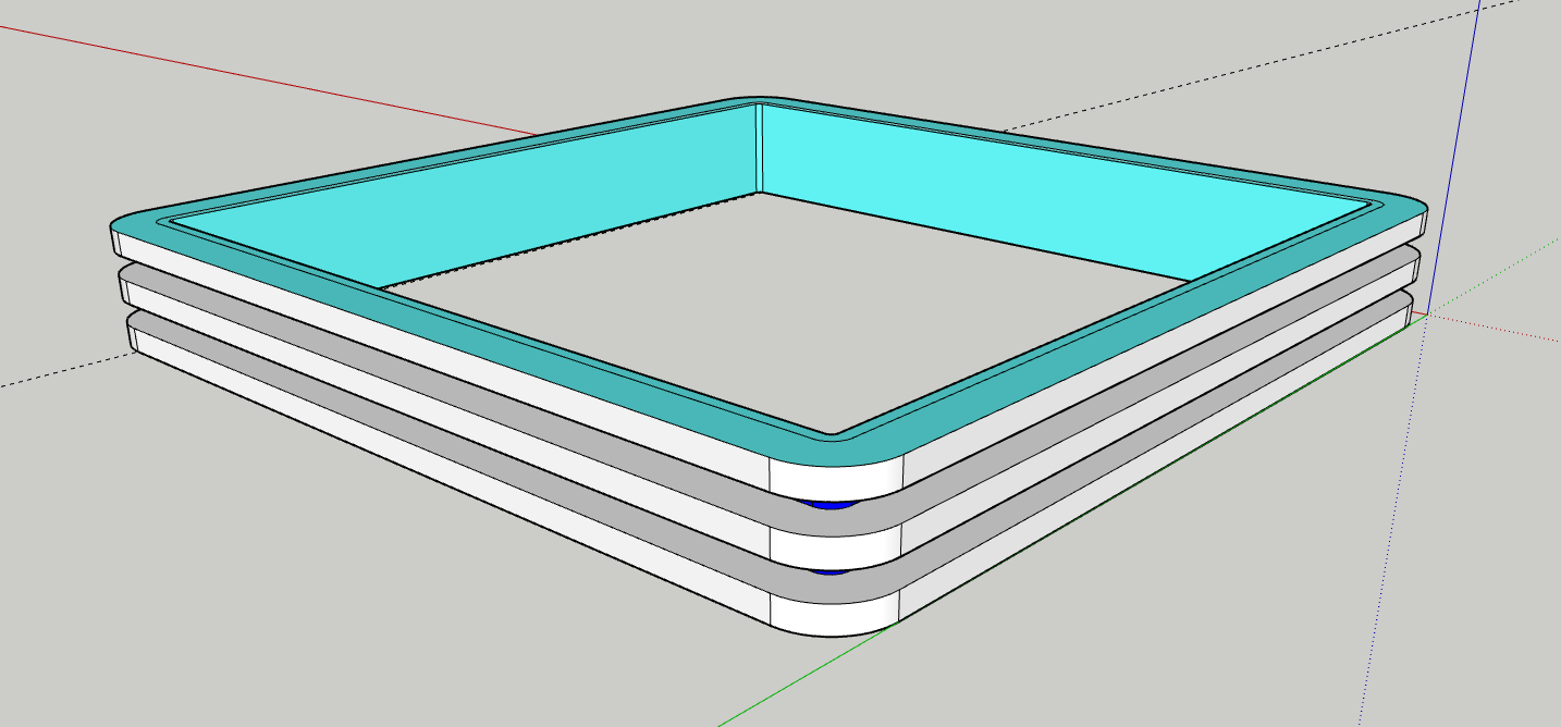
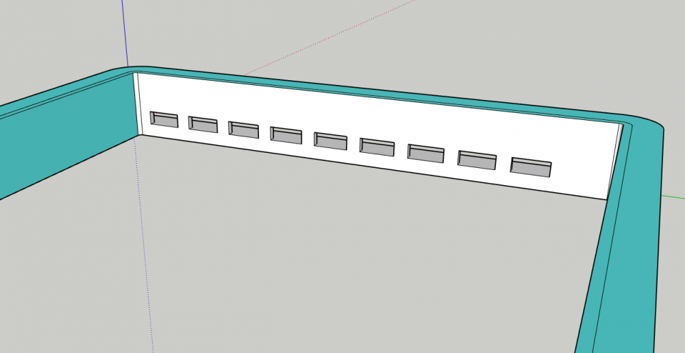
Well hopefully you don't. I didn't notice this until the one day I turned the MVHR off due to a neighbour bonfire and saw the jump in stat temps. Anyway, now SOLVED ?. The thread correspondence showed me a single gang spacer. So brought some today. Attacked with 8mm router to make slots and now temperature variation is cured. Note when I took the head off, laid it adjacent whilst I fitted this up and then put back, it kicked off with a temperature offset of nearly 2 degs to what it had been reading in situ. So see pictures. I've done one as shown and another with slots adjacent to the wall. Both seem to work well. Temperature measured by top slot is 2 deg more than room temperature.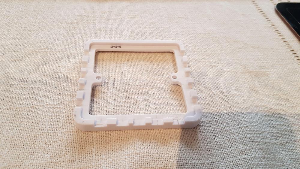

- 150 replies
-
- 3
-
-

-
- neostat
- temperature
- (and 1 more)
-
Heatmiser Neostat v2 temperature sensor problem
Ultima357 replied to Ultima357's topic in Underfloor Heating
In discussion with Heatmiser they were saying it's because my walls are insulated stud construction, so heat is not disappating from the psu, coupled with my passive super airtight build. If yours are in solid walls and you have a higher air movement then I'd expect the self heating to be less. I've pointed out to Heatmiser that stud walls have to be acoustically insulated according to building regs, so they should sort their design out to cope. Irrespective of this, having some additional ventilation in the faceplate would be good practice. -
Heatmiser Neostat v2 temperature sensor problem
Ultima357 replied to Ultima357's topic in Underfloor Heating
Yes that is the idea. PeterW put me on to ready made spacers at Wickes which would make life quick and easy to drill a dozen or so holes in. I'll experiment. Thanks for all your suggestions though. -
Heatmiser Neostat v2 temperature sensor problem
Ultima357 replied to Ultima357's topic in Underfloor Heating
Yep, that's a good one. You are correct, the transforrmer/psu and relay are in the back box behind the octagonal plate. You just ease the screws, rotate slightly and it all comes forward. Undoubtedly the source of the heat as I've measured the face of the octagonal bit at 29deg. -
Heatmiser Neostat v2 temperature sensor problem
Ultima357 replied to Ultima357's topic in Underfloor Heating
Yes, they look like the business. Just need ventilation holes all round the edge and in white plastic. I'll get to butchering a standard one first to see if it works out, they're only about a quid. But that said, see my post above about the remote thermistor also curing my interference problem. Might be a combination of these two ideas that wins the day. -
Heatmiser Neostat v2 temperature sensor problem
Ultima357 replied to Ultima357's topic in Underfloor Heating
Hmmm, don't know is the answer. The relay is all part of the moulded lump behind the backplate not shown in my pictures, so you'd have to remote the whole bit, meaning an 8 way low voltage wiring. All gets a bit messy considering I have 11 of the 14 to do. Think I'm going to try the standard surface back box idea as well as the remote thermistors which I've already ordered. The remote thermistor I've already experimented with works, just need to make it pretty. I also found out today, chasing the interference fairies caused by the central vacuum system (which I think I mentioned in the first post) , that the remote thermistor overcame this issue too. This is a very weird one caused by the 12v switch line of the central vac. Tried decoupling capacitors on it today to no effect. Run the vac, and the stats show a gradually increasing temperature which continues to rise 0.1 to 0.2 deg after vac is turned off before drifting back down to normal. It's like the interference causes the thermistor to heat up.... As I said, it's a weird one. -
Heatmiser Neostat v2 temperature sensor problem
Ultima357 replied to Ultima357's topic in Underfloor Heating
Wiring diagram below. This might help everyone understand how it's wired. Left hand diagram shows the wiring to Heatmiser wiring centre which operates the UHF actuators, turns on the pump and calls the ASHP into action. The 230vac circle indicates the psu for the stat faceplate.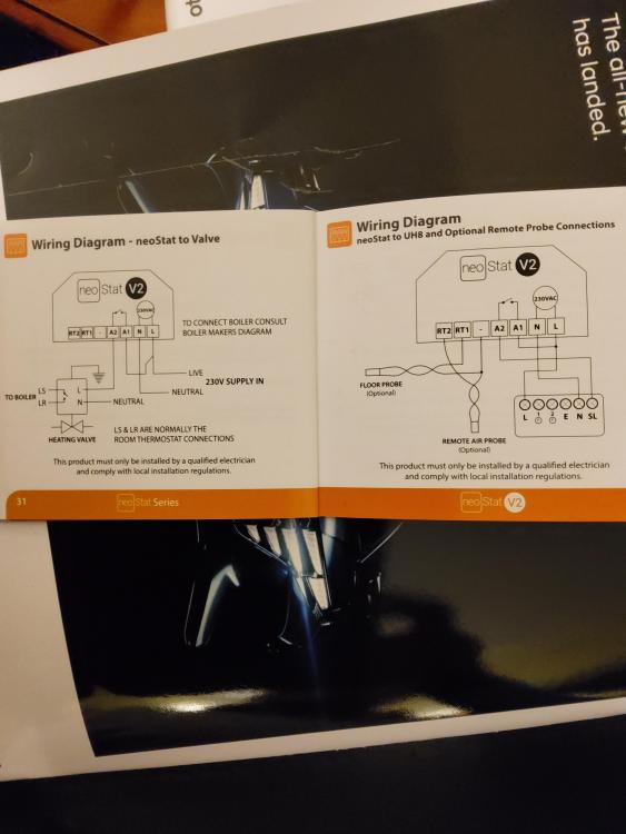
-
Heatmiser Neostat v2 temperature sensor problem
Ultima357 replied to Ultima357's topic in Underfloor Heating
Unfortunately not. It switches the mains to trigger the uhf actuators via wiring centre.