Tony L
-
Posts
385 -
Joined
-
Last visited
Everything posted by Tony L
-

Europe’s heatwave is the hottest and most humid ever
Tony L replied to SteamyTea's topic in Boffin's Corner
Sorry. I should not have insulted you. I'm careful not to antagonise or upset my friend as I try to steer her away from the information sources that inform her world view & I should have taken the same approach with you. -
Europe’s heatwave is the hottest and most humid ever
Tony L replied to SteamyTea's topic in Boffin's Corner
This is what my friend, Rebecca, says. & she knows a thing or two: she explained to me how the moon landings never actually happened – the US government paid Stanley Kubrick to film them in a studio. & did you know con trails aren’t just water vapour? They’re biological sprays or something that the government use to control us. Something like that - I don’t really understand. I bet @Spinny could explain it to me. -
Insulation upstand when not having skirting board?
Tony L replied to flanagaj's topic in General Flooring
About 5.3m wide & 6.4m deep (external measurement for the slab). I'm planning a ring beam, hung off screw piles then I'll build up the middle with hardcore & 70mm crushed concrete, non-woven membrane then sand blind the middle, get my DPM in, tape it up to prevent leaks around the screw piles & joins (self compacting concrete leaks almost like water, I have learned), rebar mesh on some castles & tied to the screw piles so it doesn't float, then I'll have some ready mix SCC delivered. I'm thinking a chute will do - I don't want to pay for a pump. I'm expecting the SCC will just flow to where it needs to go & won't require too much work to push it around. I could tamp using the top of the shuttering, which I will set with a laser, but I don't think tamping will be required. For SCC, I know I definitely shouldn't work it with a poker, as this would ruin the homogenous nature of the mix, & weaken it considerably. I've decided to forgo a layer of insulation in the slab, so I only have to pay for one concrete delivery. A while ago, I worked out that mixing this volume of concrete myself would not be any cheaper than ready mix (for ordinary concrete), & I'm expecting the SCC to be around £300 more than ordinary concrete, whilst saving a lot of bother. I have very little practical building experience, although I have succeeded in making two concrete garage bases, most recently 20 years ago, & not with SCC, so any critique of my plan will be most welcome, please. -
Insulation upstand when not having skirting board?
Tony L replied to flanagaj's topic in General Flooring
Thanks for bringing my attention to SCC, @Nickfromwales. @flanagaj, according to a conversation I had with Gemini AI, you'd use a dapple bar, rather than a bull float with this. Based on watching one YouTube video, it looks like an easy enough DIY job for my small garage, although I think I'd be inclined to to pay some experts to do this for me if this was my house. The sealant, which goes on soon after the pouring & dappling, is super important. -
Very well done, @Captain Scally.
-
Is bare OSB, or even painted OSB a good idea inside a habitable room, especially a garden room, which could get very warm inside during the summer? I'd be looking into the possible harmful effects of VOC off gassing if I was considering this.
-
I was thinking I would do the same (assuming I ever get that far with my build, which is not going well) although I am also intending to have a soft outside tap for car washing. The water is very hard in my area.
-
At my wits end with brick layers. Advice please.
Tony L replied to flanagaj's topic in Bricklaying, Blockwork & Mortar
Yes, although, it can lie a little bit, if half a hose is in the shade & the other half is left in blazing sunshine like we're going to have over the next few days. But it's easily checked, by bringing the two ends of the hose together. -
Or have some lovely steps at your front door & make your Part M level access at the back door.
-
Agreed, @Mr Blobby. That's a good improvement on the computer putty coloured one above. I've always been surprised at how very ugly most of these units are. I suppose the designers have mostly spent years designing units for commercial buildings & ugly is cheap, & it doesn't matter. It hasn't occurred to the designers that their creations blight the appearance of so many homes & many people will pay more for a competitor's less ugly design. Same goes for MVHR units; Zehnder have some nice looking designs, but if I choose something else, I'll have to build a cupboard around it.
-
South Cambridgeshire Local Authority, yay/nay?
Tony L replied to Gema's topic in Building Regulations
This has been my experience so far. Good for you. Show no mercy. -
Void Behind Bay Window Roof - How bad of an issue is this?
Tony L replied to EinTopaz's topic in Heat Insulation
& the current era as well, if the builders & architectural technicians I have employed are representative of today's building industry personnel. -
Local Authority Refusing To Visit - No Sign Off
Tony L replied to BTC Builder's topic in Building Regulations
I'm sure you could find out, easily enough. I know where mine is, & it's not very far away, so a personal visit would be easy for me. My approach wouldn't be right for everyone, of course. I don't mind inviting myself into somebody's office & making a nuisance of myself. Sometimes it works; sometimes it doesn't. @BTC Builder. If it's any consolation, I am quite envious of your problem. I think I am years away from sign off stage, & I expect to be badly let down by many more people and organisations before I get there. You're at the last hurdle. Well done you. -
Local Authority Refusing To Visit - No Sign Off
Tony L replied to BTC Builder's topic in Building Regulations
I would go to the council office & be reasonably polite, & very, very assertive. -
Thanks, @DIYMichael. I like the look of the Base Camp masks you recommend, & I've just placed an order. The Makers Manual discount was applied automatically at the checkout - thank you.
-
I've done some research & I have a good idea of how it will all fit together. I will draw it all up myself, before I begin. Thanks for the website tip. I'll be sure to take a good look at it. Rather than screws, I think I might buy a nail gun. £400. It would save me some time & could be used on the house build too.
-
Well done, chaps. That's inspiring. I'm planning to do a 5m x 6m garage on my own, within the next few months. I have a friend in the next village who will come & help me (although he doesn't know it yet) lift the walls & get everything vertical/square. My garage construction experience to date only covers making concrete bases (easy enough), & a little bit of block work three decades ago (I wasn't good at this). I have persuaded myself I will be much better at working with timber than with concrete blocks. I'll let everybody know what happens, so that others may learn from my mistakes.
-
This is one of the concerns I have for the biggest room in my build (which is well over a year from completion), although I'm confident I'll be able to solve the problem with some cheap DIY acoustic tweaks (thin pads on the ceiling, soft coving, absorbent art work, etc). I can't stand trying to hold a conversation in a room with loads of reverb, & if my hi-fi is not performing as it should I get quite annoyed. A friend's new house suffered terribly from this reverb problem when she held her house warming party. It was very difficult to decipher what was being said in her 70m2 or so room with vaulted ceiling & several different conversations going on at once. By the time of the next party, there were two sofas & a big (4m wide) floor to ceiling book case full of books, & the problem was gone. I briefly considered having a slightly sloping ceiling & non-parallel walls, for the benefit of my hi-fi, but I decided this would be impractical.
-
Communicating with the builder
Tony L replied to Bancroft's topic in General Self Build & DIY Discussion
Why not email him? He can reply whenever he has time; you have a record of everything you've asked him. -
Patio rail system - thoughts?
Tony L replied to mistake_not's topic in Landscaping, Decking & Patios
Yes, but not me. I saved this screenshot from a thread on here (probably over a year ago). I think the top picture is just a marketing picture - it doesn't look very stable to me. @Russdl's work looks better.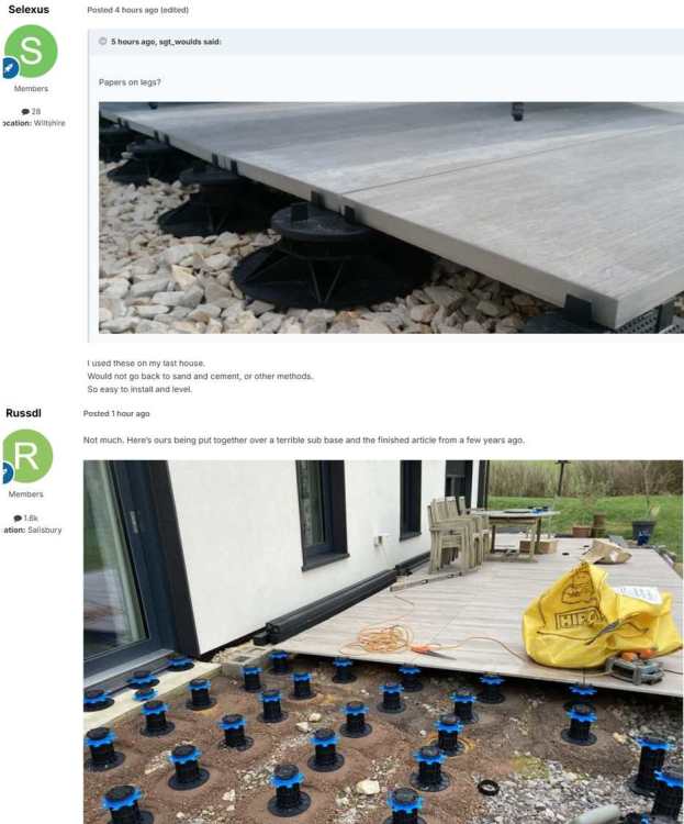
-
I expect so. The difference in thermal resistance is not small, & the Thermoblocks aren't going to crack, either.
-
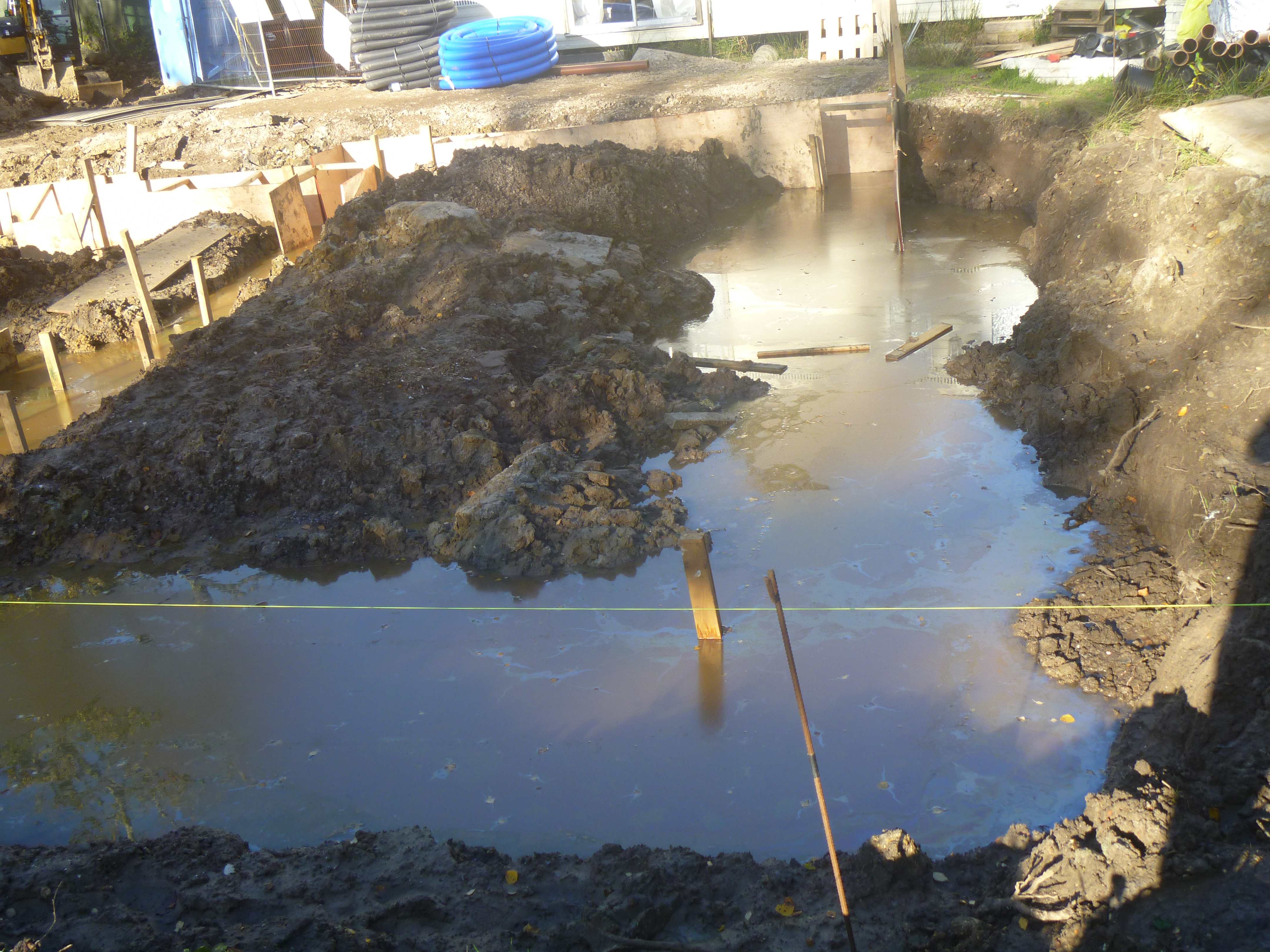
Maybe have a pump to hand too - a proper one that's designed for filthy, gritty water.
-

-
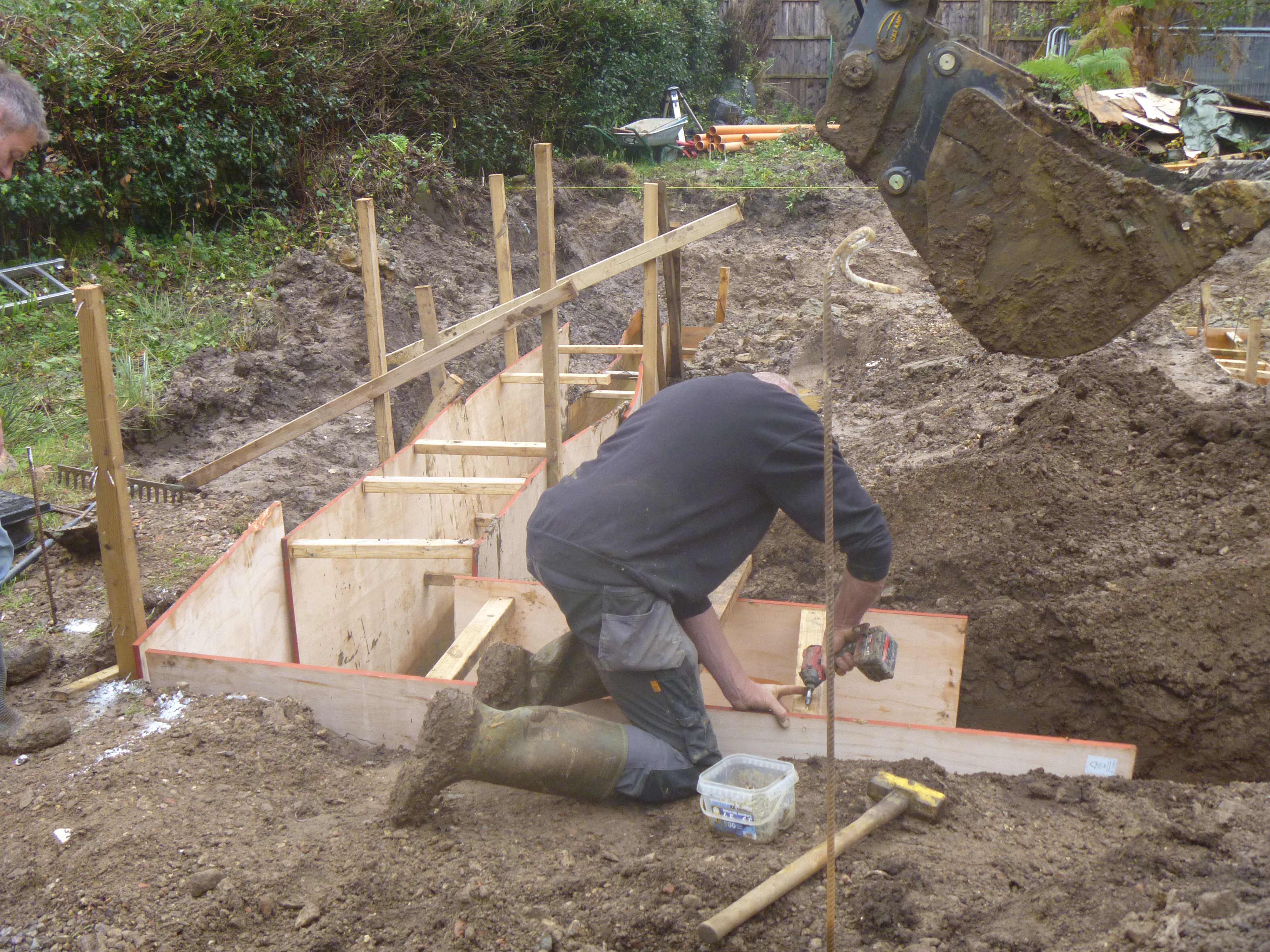
Perhaps it may be OK if your ground type drains quickly, your water table is low & your foundations are not so deep as mine, but having had experience of problems digging foundations after wet weather, I definitely wouldn't be doing it in my locality this week or next. Here's a picture from just after we started pulling the foundations. Shuttering was required to prevent the trenches from collapsing. 2nd picture is the same trench, with the picture taken from the other end. it didn't rain in between - it took the water 2 days to come up to water table level. Perhaps you should dig a test hole, then wait two days to see what happens.

-
I need about 75 x 100mm wide Thermoblocks & 18 x 215mm wide Thermoblocks to deal with the perimeter (inner leaf) & internal block walls on my design. Based on the very first website I looked at, these will cost no more than £1200, allowing for overs. I haven't worked in the cost of the special glue, but neither have I deducted the cost of whatever might have gone where the Thermoblocks will go. Given the anticipated value of the completed house, & more importantly, the added comfort & other benefits, I'm happy to spend the £1200.