Annker
-
Posts
226 -
Joined
-
Last visited
-
Days Won
1
Everything posted by Annker
-
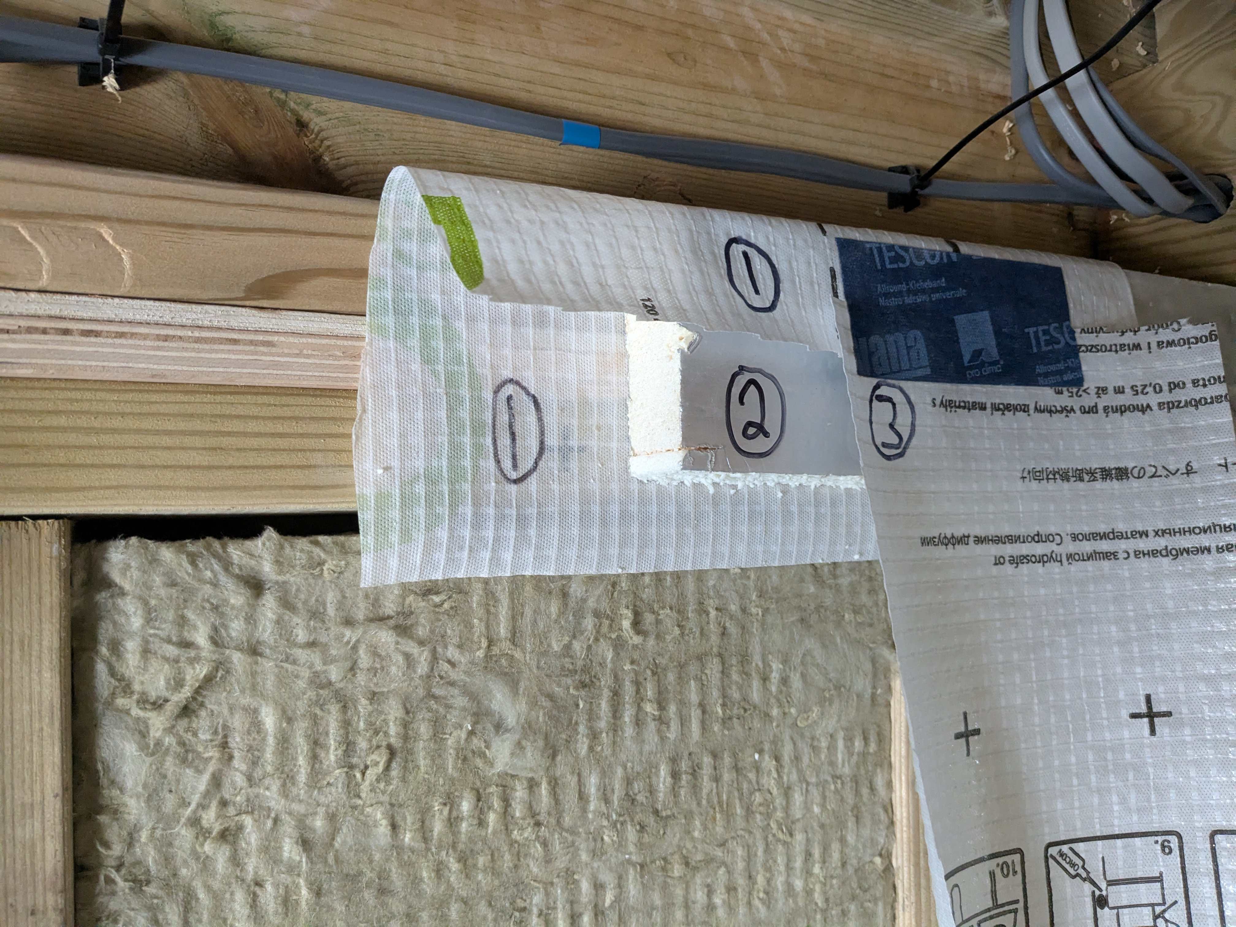
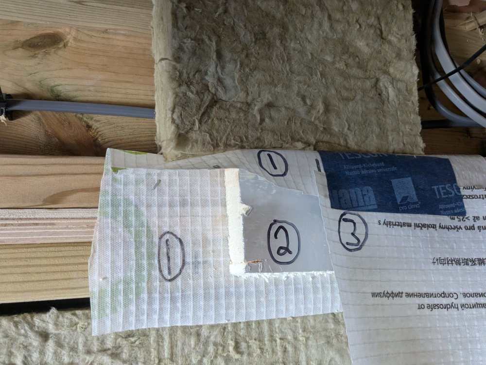
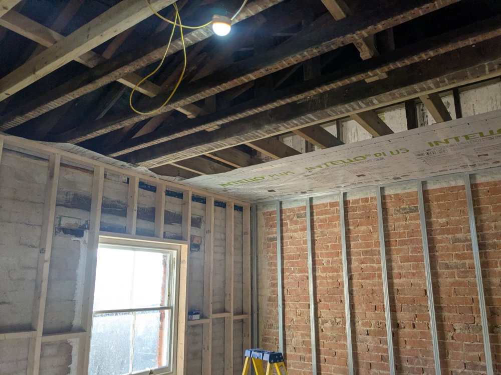
So the time has arrived to overcome this problematic detail. The solution below while not ideal aims to at least compartmentalise any shortcomings and keep the wall stud buildups safe from condensation risk: Detail is as follows below and as per attached photos of the mock up : Staple a ~200mm wide perimeter strip of intello AVCL along the top plate of the studded walls Install overboard insulation (60mm PIR board) Install main intello AVCL sheet over PIR board and tape it to intello perimeter strip. Apply air tight paint to junctions/corners within joist voids and pockets Install Rockwool batt within joist voids and pockets Appreciate any critique of my detail. Its a bit of a work around but should be easy to implement and perform reasonably well.

-
Fine tuning my IWI Solid wall (Warm Batten) design
Annker replied to Annker's topic in Heat Insulation
Will do and thanks again for all your input. Received great advice from yourself and other here, and confident I have a good understanding of the principles at work. -
Fine tuning my IWI Solid wall (Warm Batten) design
Annker replied to Annker's topic in Heat Insulation

-
Fine tuning my IWI Solid wall (Warm Batten) design
Annker replied to Annker's topic in Heat Insulation
-
Fine tuning my IWI Solid wall (Warm Batten) design
Annker replied to Annker's topic in Heat Insulation

-
Fine tuning my IWI Solid wall (Warm Batten) design
Annker replied to Annker's topic in Heat Insulation

-
Fine tuning my IWI Solid wall (Warm Batten) design
Annker replied to Annker's topic in Heat Insulation
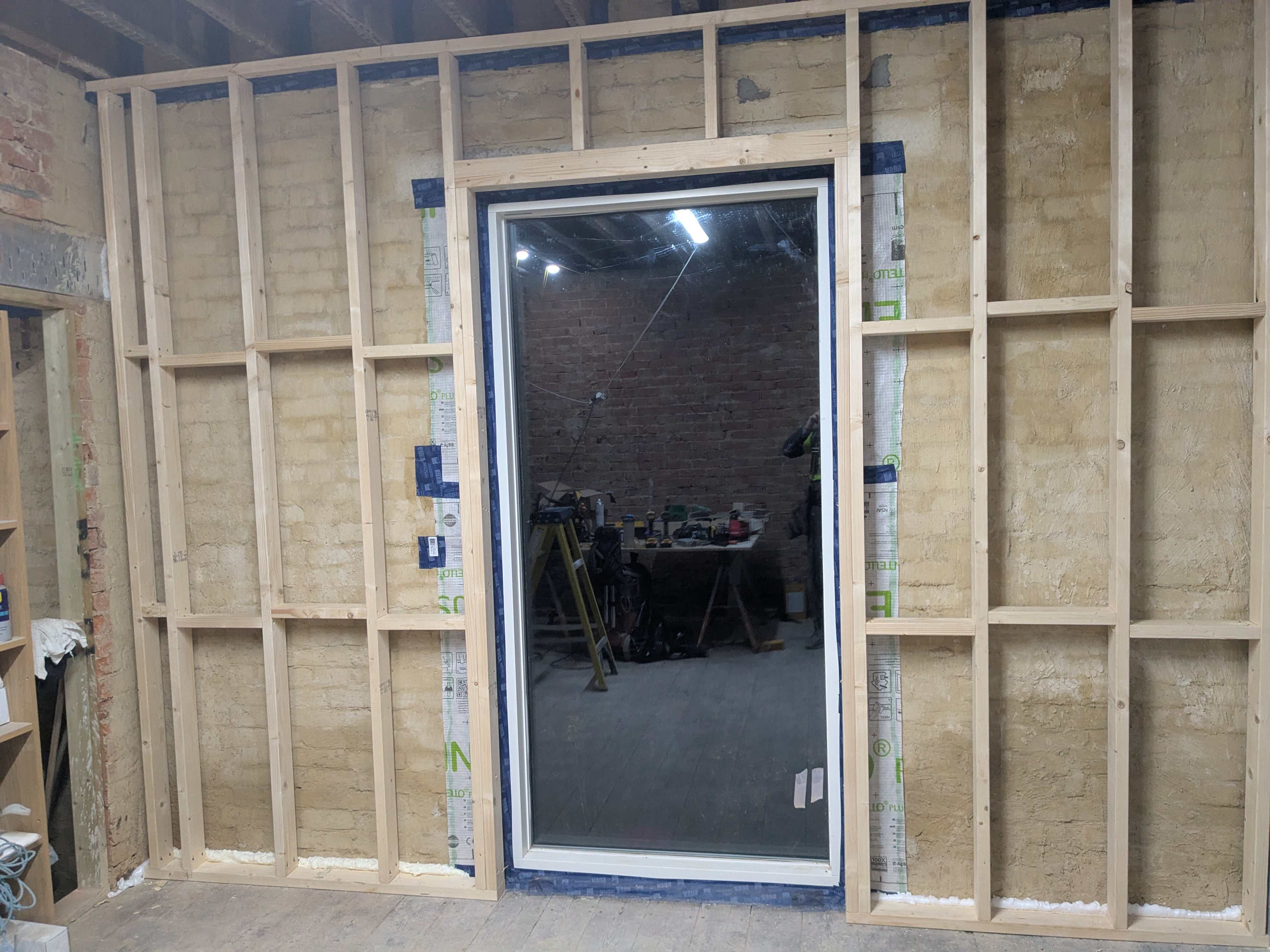
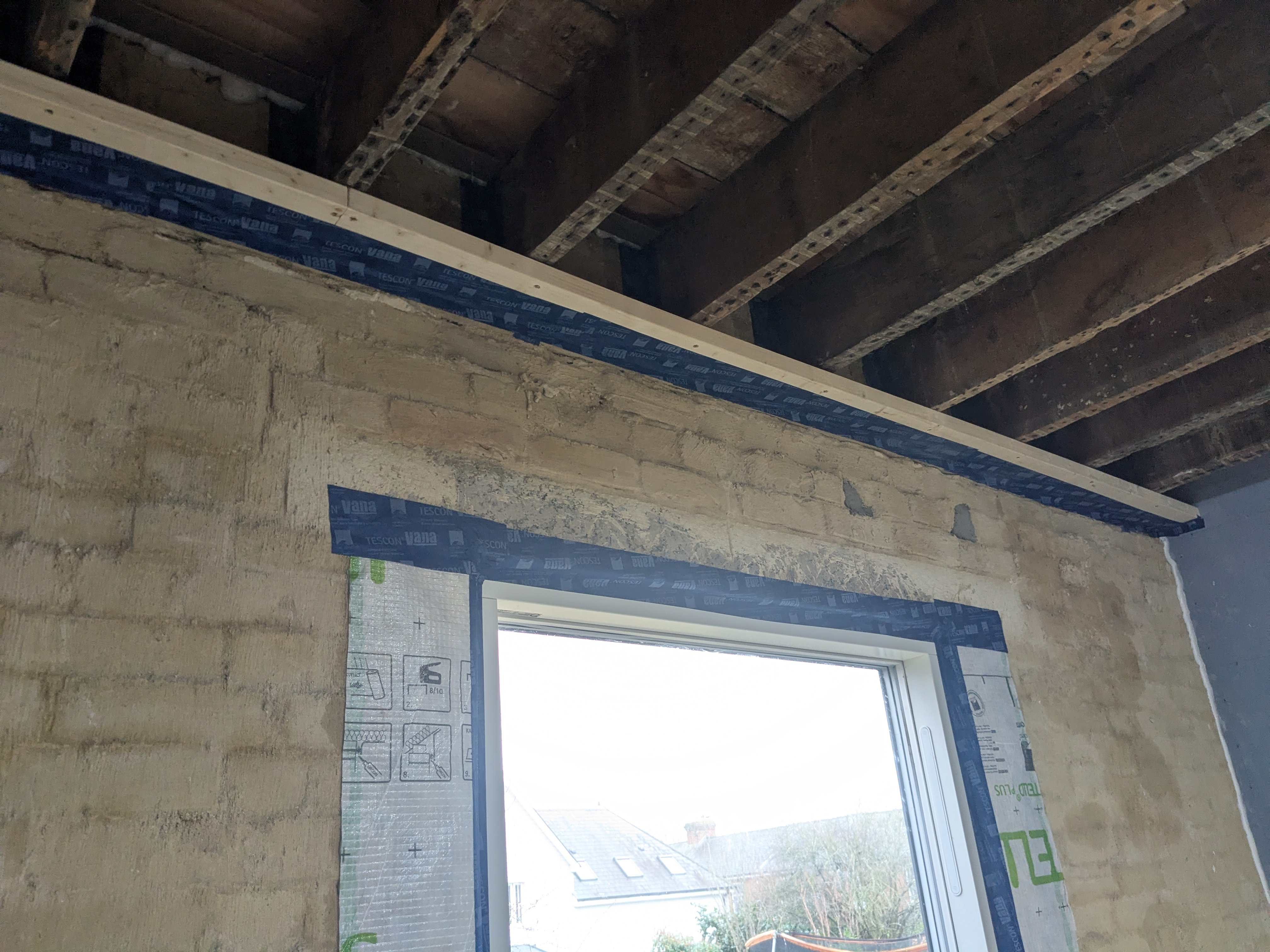
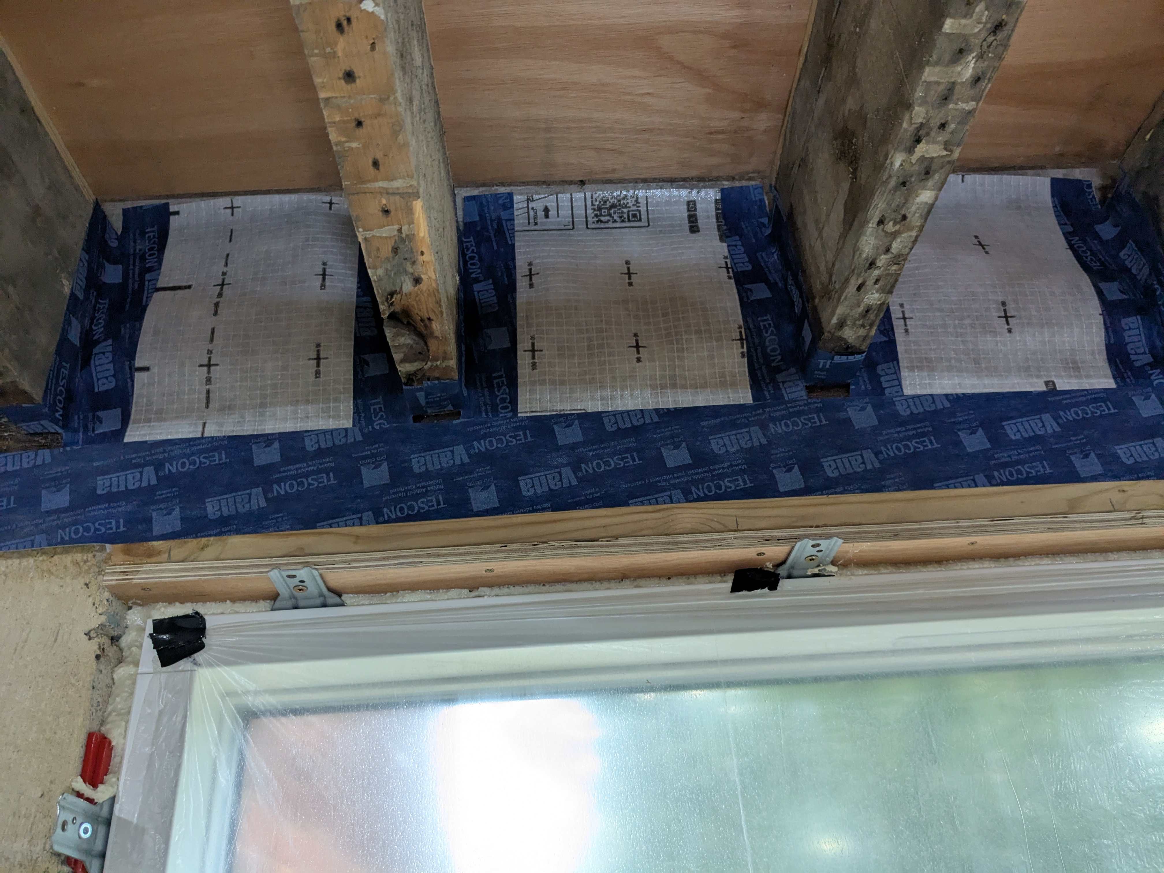
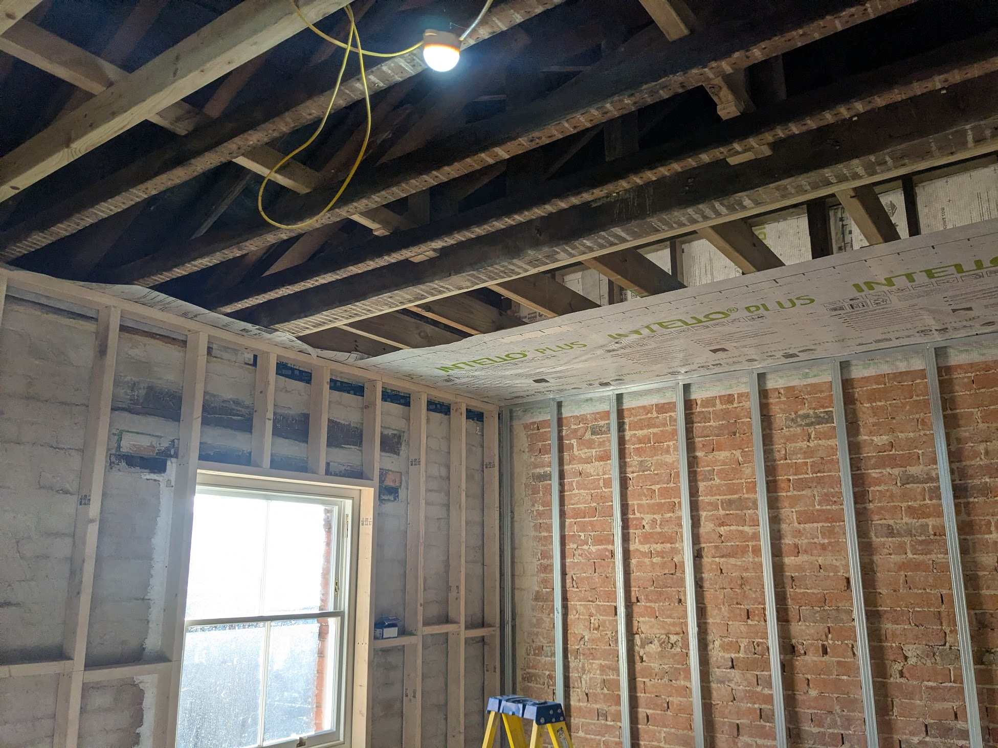
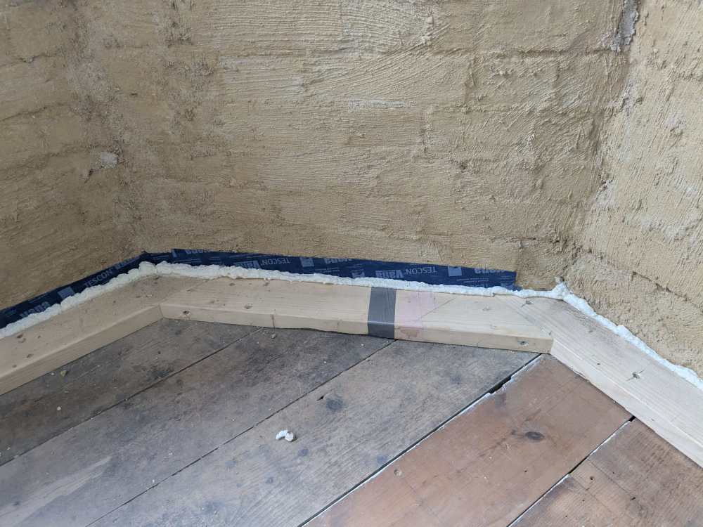
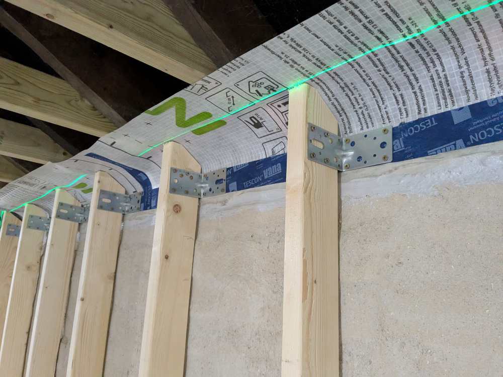
Thought I'd do a photo dump of some the onsite installation of the details discussed and generously advised on by some of the member here. Just some notes of interest if you are doing a similar job: Lime parge coat. Absolutely brilliant base before doing anything. Fast to apply, inexpensive and It has sealed up the walls greatly. What I have also noticed is the complete lack of any insects, mold or any living organism on the walls, I'm assumed this is due to the dryness and alkaline nature of lime. Pro clima Tescon tape. Not convinced how well this tape will stay adhere to masonry over decades, stick better to timber and best to membranes so assemble it around joist ends accordingly. And get the primer as it greatly increases the bond. Airtightness of studded walls units: I build the wall studs in situ, and before I installed the individual studs I ensured that the floor/ceiling to sole/head plate junctions were airtight. I used a combo of Illbruck FM330 and tapes. I think having a compartilization model in mind is useful so if there are any individual air leaks into the build-up they wont aggregated from wall to wall, cellar to 1st floor, etc. Insulation will be Rockwool as recommended by @Iceverge I also considered using a glass mineral wool, probably also suitable and less expensive but I have better confidence that RW will sag less in the fullness of time -
Yes, typically they all quote D50 and some then quote a few other common DT's. But regardless I compared all against D50
-
Thanks John, that makes sense.
-
Hi Gus, To my mind this is not the issue, as I am comparing one cast iron radiator section against another. I called CIRC and as expected they can't give a specific reason why their section is upwards of 25% more efficient than all others, but they can say that no customer has raised this issue before. Is it just my experience or do the majority of building product suppliers in the UK seem clueless about their products. Anyway, as you also suggest I think if I use CIRC it is wise to oversize. My AI assistant summarises as such: Bottom line: With an ASHP, the risk profile is asymmetric. Undersized radiators force higher flow temperatures and reduce efficiency. Oversized radiators allow lower flow temperatures and improve efficiency. If you must err, err on the side of larger. Sizing to Paladin/Carron figures while buying from CIRC is a sensible, low-risk strategy. Worst case: you've got slightly more efficient heating and spent a bit more on radiators. Best case: you've sized correctly.
-
I've also noticed that CIRC state that a 4 column 760x1310 has an output of 2400W; where as their 3 column 745x1310 has an output of 2403W. A smaller section with one less column having a greater(albeit slightly) output surely cannot be correct or am I missing something?
-
Adds a bit more context that the Cast iron radiator centre are claiming that their 745mm high 3 column section has greater output than the Stelrad 760mm high 4 column section. It just doesn't seem likely to me. The thing is that CIRC seem to be a lot less expensive than all other suppliers, even if in reality you need to size up from their performance tables. I just want to make sure I get genuine performance figures from them.
-
Well that's what I'm assuming also; that is given that the designs, or material used are not significantly different, the outputs should be more or less the same. So the question is whether 4/5 brands are understating the performance of their product or one brand is overstating their performance. The latter seems more likely. AI suggested that I request their BS EN 442 test documentation to verify the claim output. I will do that tomorrow and imagine more than likely be met with silence.
-
I'm looking to buy cast iron radiators to install downstairs in a victorian renovation. Cast iron radiator centre are a supplier that seem to be competitively priced, if not one of the cheapest suppliers on the market. A potential catch which I am trying to resolve is the accuracy of their claimed performance (watts). I asked AI to compile a table and it illustrates as I thought, that CIRC claim their sections put out ~25% to 30% more heat than most other brands. As these sections are pretty much the same design, and I imagine are produced from same material, across all brands it seem like a claim worth verifying. Has anyone ever had the similar query? The heating system will be ASHP so I'm keen to match the respective heat loss figures for each room accurately and Obviously I don't want to end up with undersized rads. . 3-Column Cast Iron Radiator Output Comparison (~745-750mm Height) Per-Section Output @ ΔT50 Manufacturer Model Height Watts/Section Cast Iron Radiator Centre (CIRC) Traditional Victorian 3-Col 745mm 115W Shelbourne (CI Radiators 4u) 3-Column 745mm 86W Paladin Victoriana 3-Col 745mm 86W Arroll Neo-Classic 750 745mm 92W Carron Victorian 3-Col 745mm 80W
-
Interesting, I wasn't aware such slim lights were available. I should have clearer that I have a somewhat specific light design intent, wrt downlighters I want trimless, small diameter and in some instances directional. For what I have seen ticking them boxes means a fitting with a min depth of ~90mm As aside on a previous project I worked with John Cullen Lighting, they were client appointed and initially I thought Lighting design was a makey uppy discipline to extract money out of wealthy home builders but I learnt a lot from them and a good lighting design certainly elevates a project to the high end.
-
Its a retro fit/renovation. I think it would be near impossible to seal the perimeter of the VCL if it was fitted above the joists, and also more difficulty to fit the insulation to be laid between the joists. Photo below for reference, as you can see its very easy for me to fit the vcl from below. I have a thread going on IWI, my design was largely gathered from very useful info received on the forum and I will updated it once that phase of works is complete
-
Yes this is a good solution for me, fully constructed boxes probably aren't necessary just need some bit of background to taped the vcl to
-
Have you a link to lights that small, sounds like a great option if required. I'm afraid shallowest light I'm using is ~90mm
-
In summary I am fitting an intello plus AVCL to 1st floor ceiling joists, these rooms will have downlights fitted in the ceiling which are about 120mm in length. I cannot create a service void below the AVCL to accommodate the downlights, therefore they will be located within the ceiling joist void, hence above the level of the AVCL. There is an off the shelf solution like these however I do not see any mention of them being used by builders on this forum. I am a carpenter so I could make plywood boxes into which the AVCL is folded up into. I'm sure this must be a common detail but I can't find much detail on solutions so keen to hear what others have done to maintain the air tight layer in this situation.
-
Recommended method for connecting 40/50mm wastes to a soil stack
Annker replied to Annker's topic in Waste & Sewerage
@ProDave Hopefully the manufacturers have considered that but I guess only practical "testing" will confirm. My initial plan was to run the horizontal soil from the frame at/above floor level; as opposed to below floor level within the joist void. Therefore avoiding any rearrangement of the joist solid bridging. However, from the image of the frame I noticed that the short vertical outlet attached to the frame appears longer than those on say Geberit frames. Rather than assuming that vertical outlet could be cut back to permit running the horizontal pipe above floor level I decided to call the Vitra tech dept. They didn't provide a definitive response but suggested that frame may benefit from the longer drop provided from that longer vertical outlet. Its frustratingly all too common to hear manufactures giving ambiguous advice regarding how their products perform or should be installed. -
I'm looking for some advice regarding connections soil stack. I have an ensuite and bathroom located back to back and the plan is to connect all the wastes (2xWCs, 2x showers & 2x WHBs) into a single soil stack which is located on the other side of a wall these two wet rooms share. The WCs will share a back to back concealed cistern ,the waste from this will push into 90 degree bend then a 1 metre horizontal run through the wall and then connect to the soil stack with a 90 branch. My question is if there is a preferred method of connecting the shower and WHB wastes to the soil stack. A neat option could be to combine the 2x shower waste connections to the stack along with the WC connection with this triple socket 90 branch. Or is it better to use strap bosses or even these McAlpine bosses and make individual connection to the stack? Also are there rules concerning shower/WHB wastes connect to a soil stack above/below WC connection to the stack?
-
Thanks John very helpful. Plan is not to have a hot return, therefore in very simple terms for now this would look schematically like: 22mm or 15mm pipe from the cylinder to a 6 port manifold located in the cellar adjacent to the cylinder, or possibly in the utility room above Then from that 6 port manifold 6x single 15mm pipes to: Bathroom Ensuite 1 Ensuite 2 WC Kitchen Utility Then within each bathroom/ensuite a 2 or 3 port manifold feeding shower/basin/bath as necessary.
-
The distribution valve sounds like a clean solution. Being able to 2nd fix each bathroom as and when, and then simply turn a respective isolation valve to bring them online without affecting the heating system would be ideal.
-
I had imagine that "in theory" a contractor should quote the same baseline figure whether going the MCS route or not. Then add on additional administrative costs (unsure if the installation differs and raise some more additional cost) which add up to being less than the value of the grant, therefore making MCS financial incentivised. Although perhaps in reality contractors are miking the MCS a little. From the single quote I have had returned, I thought it read that the contractor was deducting the £7500 grant from his cost/my bill and would apply and receive that payment directly himself. Although I may have misunderstood how that works, and in fact I have to pay the contractor that £7500 and then I have to wait for reimbursement. Regardless a good point to be nailed down prior to work commencing. WRT a piece meal setup, it does sound a little bit messy and in my experience that's when systems start to have problems. If the heating was all fully installed, but the domestic HW (bathrooms) were piecemeal would that still require a buffer installed until the heating and all the HW were fully finished?
-
Yes Sharpener that makes sense, perhaps If the rad installation was left within the ASHP package it may help a cleaner commissioning process. I have read about the umbrella route but where I am happy to (at least consider) taking on the 2nd fix, I will certainly leave the heat systems proper to a MCS reg'd contractor.