MortarThePoint
-
Posts
2168 -
Joined
-
Last visited
Everything posted by MortarThePoint
-
Using damaged plasterboard
MortarThePoint replied to MortarThePoint's topic in Plastering & Rendering
I can understand the concern if the crack isn't supported by material behind, but ultimately if you just treat it like a join surely(?) it can't cause any problems -
I have two sheets of plasterboard that snapped whilst being carried. They didn't get dropped, but the snap is straight across and the sheet folded to near right angle. I saw in the BG book it says not to use damaged sheets, but how do you feel about this? They are moisture resistant and for bathrooms where they will be over OSB. On one sheet the crack is square to the edge of the sheet so much like how you'd join a sheet. On the other it's at a slight angle so may be no good. If using the one that's square, I could cut it clear and leave a small joint for the plaster skim.
-
OSB / Plasterboard bathroom walls
MortarThePoint replied to MortarThePoint's topic in General Construction Issues
BG give the guidance below when it comes to wall tiling. I presume an 11mm sheet of OSB counts as equivalent to a 12.5mm plasterboard and so it's OK to use 12.5mm over it?
-
OSB / Plasterboard bathroom walls
MortarThePoint replied to MortarThePoint's topic in General Construction Issues
Thanks this is all really helpful. So sounds like the winning recipe is: Studs at 400mm c/c (70mm C-studs in my case) OSB (in my case 11mm) onto studs, held 15mm off the floor screed 12.5mm moisture resistant plasterboard onto OSB, held 15mm off the floor screed Plaster skim (Thistle Multifinish or is there a better choice for bathrooms?) Tanking solution (any recommendations?) CT1 shower tray against the plastered wall and tile above as needed Elsewhere, use cementitious tile adhesive to fill the 15mm gap when tiling the floor -
OSB / Plasterboard bathroom walls
MortarThePoint replied to MortarThePoint's topic in General Construction Issues
I've sat the 11mm OSB on offcuts of 11mm OSB so am a bit shy of the 15mm. I haven't fitted the plasterboard yet though so could try cutting 4mm off though could be tricky. -
I was hoping for some tips on using OSB under plasterboard in bathroom walls. How far off the screed should the bottom of the OSB sit? Particularly next to the shower tray should I raise it clear of where the top of the shower tray will be and use either smaller OSB offcuts on the studs as packers or perhaps use 11mm thick timber there? Is it worth treating the bottom of the OSB with anything? How far off the screed is it normal to raise moisture resistant plasterboard? Note both of these are distance off screed not off top of tile. I plan to tank the plasterboard when done. Is that considered a good approach or will it create difficulties for tiling or plastering?
-
Stud walls 600c/c vs 400 c/c
MortarThePoint replied to WWilts's topic in General Construction Issues
I'd be worried about having the 63x38 CLS studs that way round. The deflection under the same load is 2.7 times as much in that orientation and thickness in the line of the load force is king for keeping deflection down. 600mm centres compounds it further and makes it 4 times floppier than 400mm c/c with 63x38 CLS in the correct orientation. You'd probably be better without staggered studs and using resilient channel or think about using Metal C-studs (also Acoustic studs are an option there). Second Moment of Area: (63*38^3)/12 = 0.29E6 vs (38*63^3) / 12 = 0.79E6 -> 0.79E6 / 0.29E6 = 2.7 Beam deflection is inversely proportional to Second Moment of Area. -
Plasterboard&OSB Return
MortarThePoint replied to MortarThePoint's topic in General Construction Issues
Here's what the return will look like in terms of OSB:
-
Plasterboard&OSB Return
MortarThePoint replied to MortarThePoint's topic in General Construction Issues
I wonder if I should have held the OSB a little higher than 10mm off the screed, but the plasterboard will need to come down about 5mm above the screed I presume. -
Plasterboard&OSB Return
MortarThePoint replied to MortarThePoint's topic in General Construction Issues
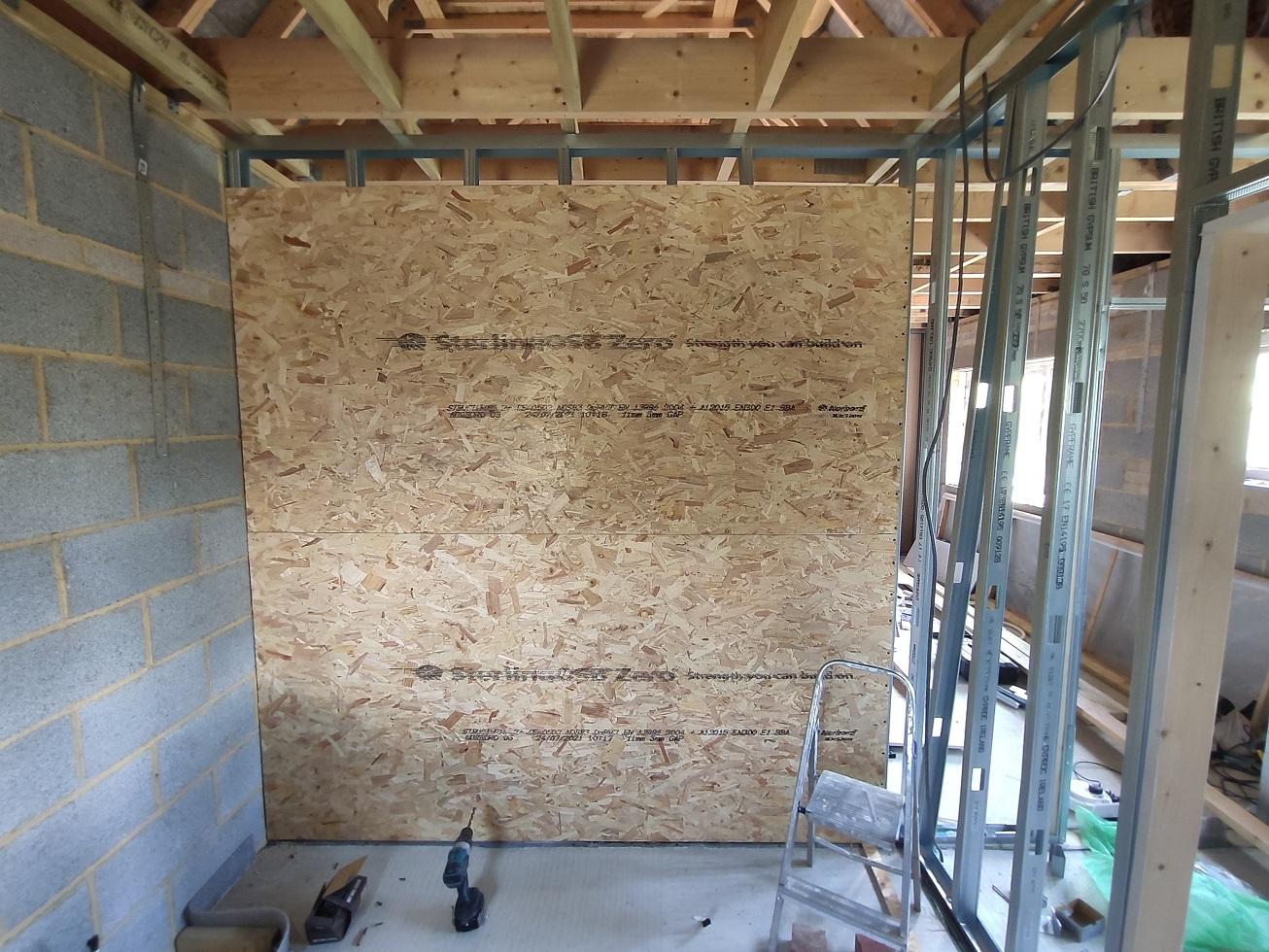
I've gone with the stripwood approach. Hard to see, but I left a 3mm gap between the two boards by resting the top one on screws sat on the bottom one whilst installing. Also 3mm gap at the blockwork and will do he same at when I add the 15mm plasterboard continuation. I've not taken the OSB to the ceiling as that is 2.7m and there won't be cause for anything up there (will there?). I'll pack the studs at the top with stripwood and strips of OSB just at the studs. I raised the OSB about 10mm off the floor, you can see a strip of OSB under the sheet edge which I will then chop up and use as above. Stud positioning to avoid pipe penetrations is the next key thing. The sink waste is going into the wall 600mm room the RHS end of the OSB (400mm stud centres). It will then pop out in the bottom left corner and I expect I will need to pass water feeds in there too to then take to the sink and continue round, into the return and over the door in the return to the shower. The other route to the shower is along with the shower's waste, but I'd need to cut a trench into the screed for it to continue past the shower trap and onwards to the stud wall. [Note: the stud in the odd position is just moved temporarily
-
Plasterboard&OSB Return
MortarThePoint replied to MortarThePoint's topic in General Construction Issues
That doesn't work so well with the 1200mm gauge unfortunately -
Plasterboard&OSB Return
MortarThePoint replied to MortarThePoint's topic in General Construction Issues
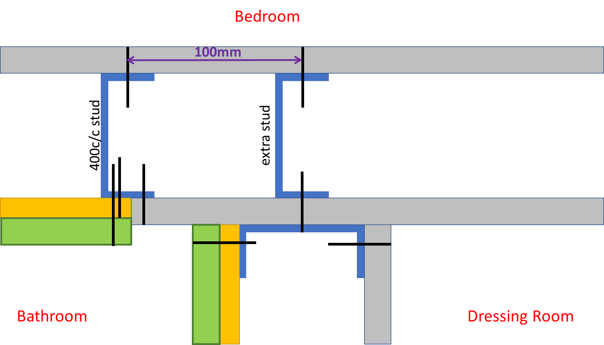
I was worried that it would affect the strength of the junction with the plasterboard stopping in free space rather than on a stud. -
Plasterboard&OSB Return
MortarThePoint replied to MortarThePoint's topic in General Construction Issues
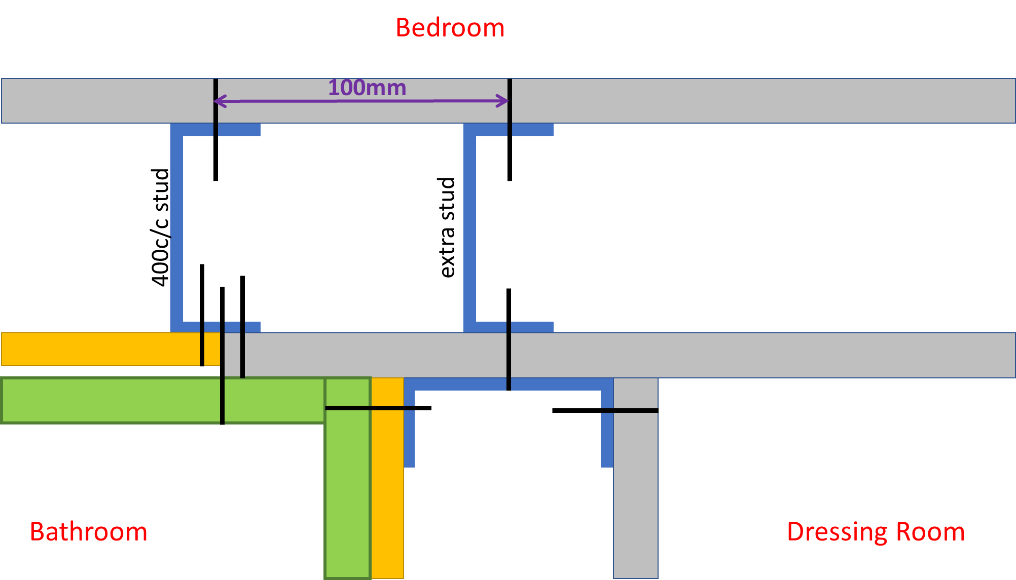
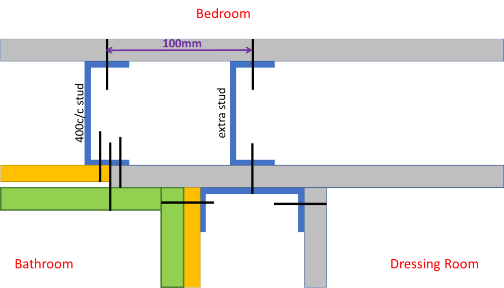
I could put 36mm x 4mm stripwood behind the OSB3 at all its studs to make it effectively 15mm: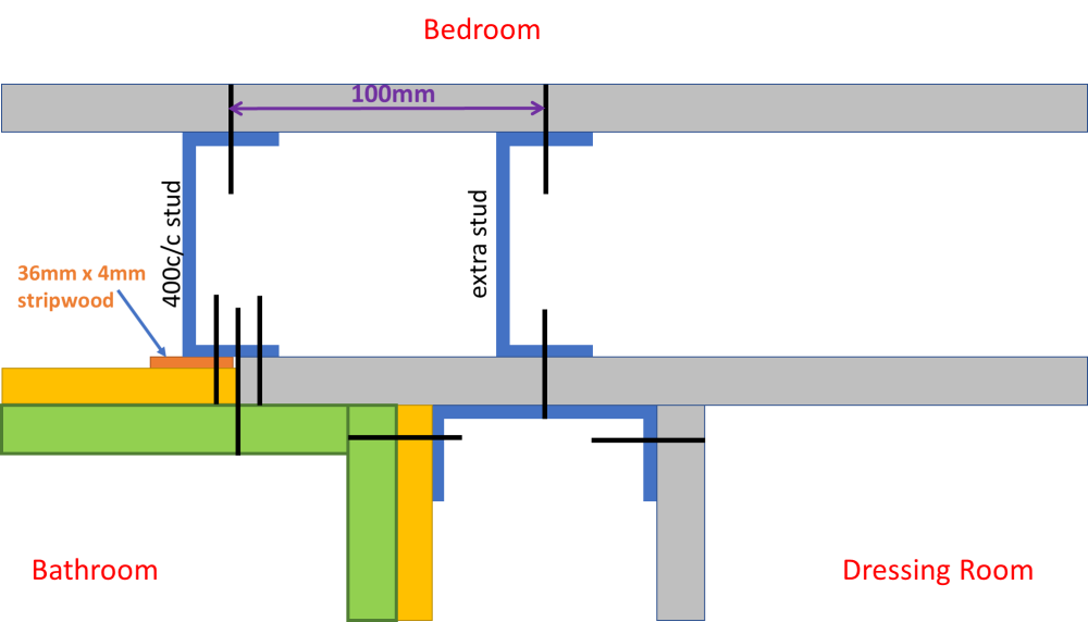
-
Plasterboard&OSB Return
MortarThePoint replied to MortarThePoint's topic in General Construction Issues
The sketch above has the issue of the plasterboard needing to come away from the OCB towards the corner. Or am I better off creating a small pocket in the corner to get filled by plaster when the wet plastering is done? They may not look it, but the sketches are pretty much to scale.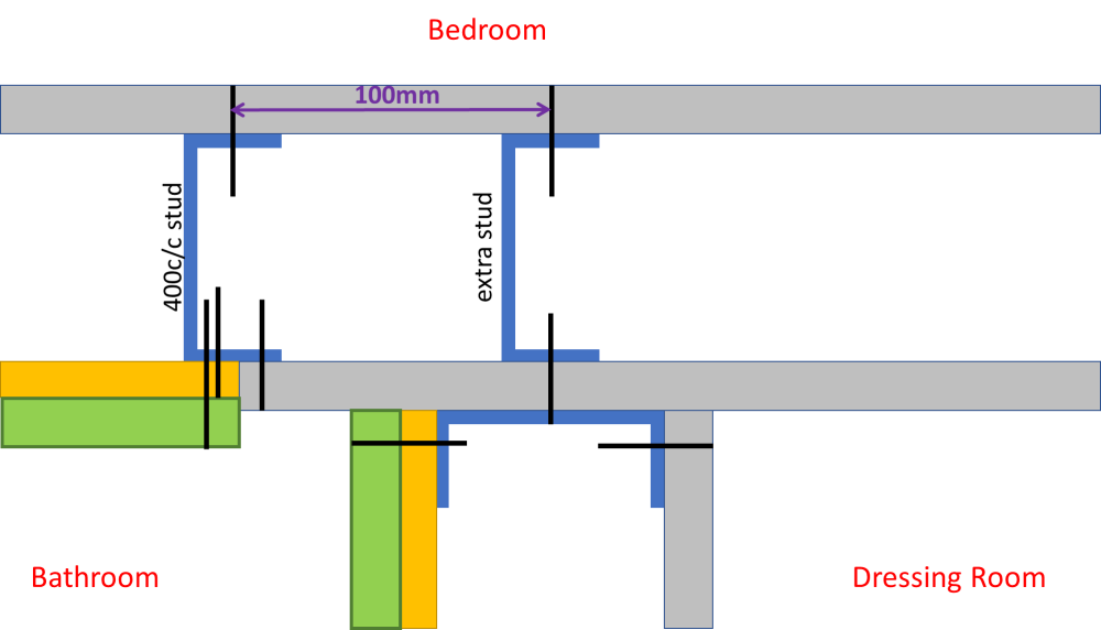
-
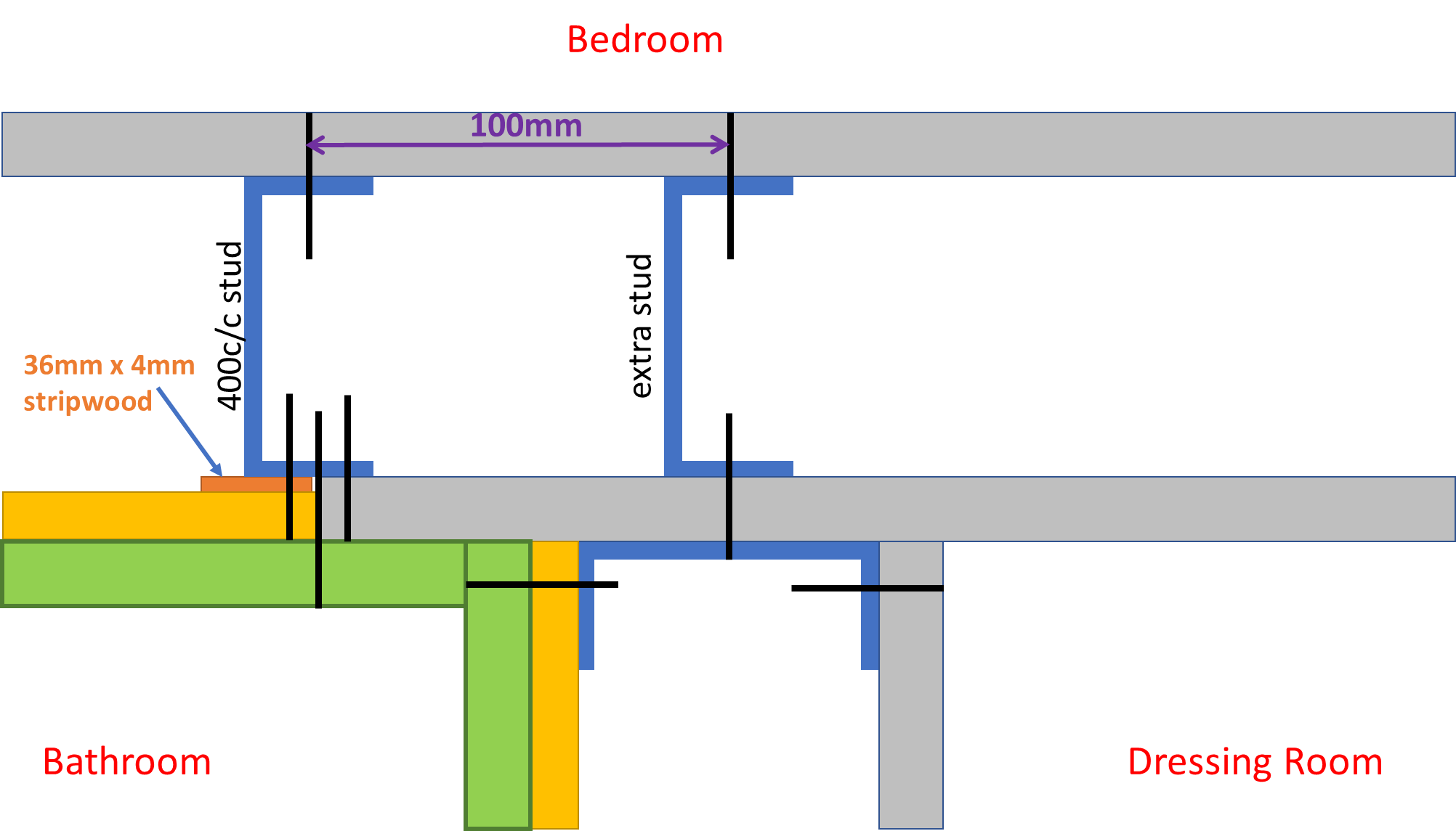
I'm looking to include OSB in the Bathroom wall but it's complicated by there being a return. The wall sheathing will effectively be changing thickness at the return which is a small challenge. Also, I may only be able to get 11mm OSB (or 18mm but same problem) which means it's not the same as the 15mm plasterboard. Below is a drawing of what I'm looking at. The green is 15mm or 12.5mm moisture resistant plasterboard, yellow is 11mm OSB3 and grey is 15mm Duraline. All on 70mm C-Studs (BG) in blue.
-
32mm Waste Pipe in Metal Frame wall
MortarThePoint replied to MortarThePoint's topic in Waste & Sewerage
The AAV could be above the sink and behind the mirror. To service the AAV, I could remove the mirror and an access panel. I suppose it raises the question of how does air enter the wall and does it bring moisture in with it? I know there are small trap based AAVs but suspect they wouldn't admit enough air to prevent the problem in this situation. 9l/s for 1¼" solvent weld pipe https://mcalpineplumbing.com/air-admittance-valves/ventapipe/vpsf-4050-ventapipe-4050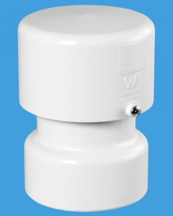
-
32mm Waste Pipe in Metal Frame wall
MortarThePoint replied to MortarThePoint's topic in Waste & Sewerage
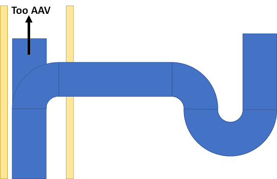
Thanks Nick. The bath is freestanding so it would be a pain to have an AAV there. Could the AAV be in the stud wall with some form of air access to the stud wall? Another option that might be possible is to keep the bath and basin wastes separate all the way to the stack. This is what I was worrying about in terms of an S-trap: Though it would be more like this I guess: Could I solve it all by having the AAV off that initial in wall elbow? If just having the AAV in the wall, I would make sure it is well above the top of the basin.

-
32mm Waste Pipe in Metal Frame wall
MortarThePoint replied to MortarThePoint's topic in Waste & Sewerage
The pipe goes about 500mm along the floor, joins the bath waste and goes 200mm down through floor before going 1800mm along ceiling void and joining soil stack. I may not pass through floor though and join stack above floor, but that area will be very busy. So I can't going purely horizontally to the stack unless I penetrate the wall at skirting board level which would be strange. -
32mm Waste Pipe in Metal Frame wall
MortarThePoint replied to MortarThePoint's topic in Waste & Sewerage
The basin would have a U-trap before the wall penetration so combined with the 90degree in the wall that would make an S-trap. That's bad for symphonic emptying isn't it? What are you thoughts on height? -
32mm Waste Pipe in Metal Frame wall
MortarThePoint replied to MortarThePoint's topic in Waste & Sewerage
Hmm, does this second drawing create an S-trap which is a no-no? -
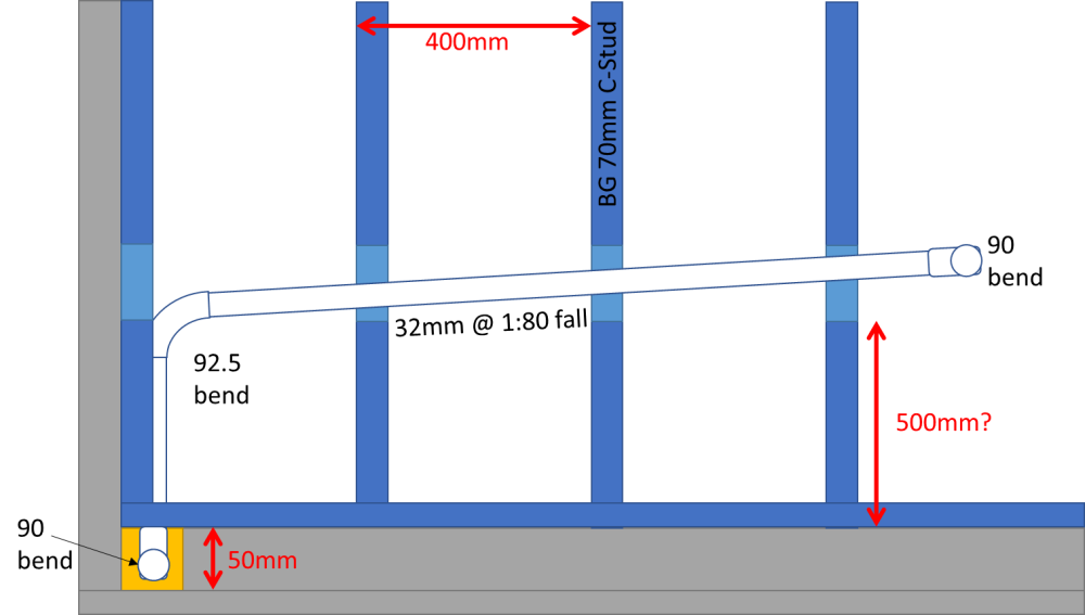
What height should my waste pipe go into the stud wall? Exciting times getting the partitions up and starts to feel like a home. I want to route the waste pipe of a basin through the wall to have a clean finish in the bathroom. There's only one place I have to do this, others are on blockwork walls or behind cabinets. The wall is 70mm C-studs (BG) and I plan to use 32mm ABS solvent weld pipe. The main question I have is what height the pipe should penetrate the wall for attachment to the basin. The basin will be a free standing one (wooden unit with basin on top). We haven't chosen this item yet and it may be one I make myself, but it would be nice to have the pipe at a sensible height that allows options. I'll probably fit a pattress to allow the future option of hanging a basin on the wall, but haven't decided yet. The cut-outs of the studs are around 500mm off the bottom, though I think I can flip them over and make it more like 300mm. Should I do that and then have a vertical section on the right of the drawing as in the second image which allows easier future adjustment of the wall penetration? At the end of the wall there will then be a vertical to get down to a trench in the screed. I hope this isn't noisy. At the moment the floor channel of the stud wall is screwed to a 4x2 which is continuous to the wall so I'll have to work out how to butcher that to make the trench go under the floor channel. If I can't do that, I'd have to box in the pipe at floor level which would be unfortunate, but not the end of the world. The trench is about 500mm long before a large hole in the floor that will be shared with a bath waste. rodding access

-
Partitions: Timbers studs Vs Metal C studs
MortarThePoint replied to MortarThePoint's topic in General Construction Issues
A point worth knowing is that British Gypsum 70mm C-studs accommodate 32mm waste pipe through their cut-outs but Tradeline don't. Neither accommodate 40mm waste pipe. The cut-outs in 70mm Acoustic studs are way to small. -
Partitions: Timbers studs Vs Metal C studs
MortarThePoint replied to MortarThePoint's topic in General Construction Issues
Here's a potential gotcha. For bathrooms, C-studs should be at 400mm c/c if using any 15mm Gyproc moisture resistant grade plasterboard. It doesn't actually say what stud c/c to use if using 12.5mm moisture resistant plasterboard. A Siniat video about metal stud partitions says they should be at 400mm c/c due to the extra weight of tiles.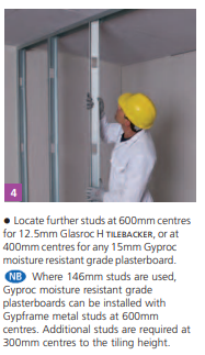
-
Partitions: Timbers studs Vs Metal C studs
MortarThePoint replied to MortarThePoint's topic in General Construction Issues
I was finding it hard to find the British Gypsum Site Book and Good Practice Guide so thought I would upload it here for anyone else who wants it. British-Gypsum-Good-Practice-Guide.pdf
-
Pitched Roof Counter Battens For Insulation
MortarThePoint replied to MortarThePoint's topic in Heat Insulation
Forgot to do the division: dU = 4.167 * (0.025m *0.002m) * 60W/mk / 0.171m = 0.073W/m2K I've checked with Arthur Hough and there AH120 (aka GL6) is 0.8mm thick. BG suggest 600mm x 600mm centres (see extract below), reducing the number per square meter to 2.78/m2. That reduces the thermal bridging to dU = 2.78 * (0.025m *0.0008m) * 60W/mk / 0.171m = 0.020W/m2K. That first number seems so large (e.g. changing 0.15 to 0.22) that it can't be right. I guess it is treating it as a bridge all the way through to cold which isn't really fair. To do it properly needs FEA. Alternative model would be to consider GL6 in series with a block of wood to cold. the length of the block of wood would be the thickness of insulation remaining past the end of the connector, so 80mm in my case. What area to make the block of wood? 27x27 : r_wood = 0.080 / 0.12*0.027*0.027 = 914, r_gl6 = 143, r_total = 1067 --> dU = 2.78 / 1067 = 0.003 47x50 : r_wood = 0.080 / 0.12*0.047*0.050 = 284, r_gl6 = 143, r_total = 427 --> dU = 2.78 / 427 = 0.007 47x81 : r_wood = 0.080 / 0.12*0.047*0.081 = 175, r_gl6 = 143, r_total = 318 --> dU = 2.78 / 318 = 0.009 Feels reasonable to assume that the affect of using GL6 connectors vs some magic non-conductive ones is dU = 0.005 - 0.010, I'm happy to work with 0.005. Removing 50mm wide by insulation_thickness_below_rafters timber battens improves the U-value by dU = 0.004 so the GL6s cancel that out and it comes down purely to cost and ease of installation. Also putting it into context, it's all equivalent to a difference of about 7mm of Mineral Wool! I was uneasy that my pitched section's U-value was rounding up to 0.15 rather than down to 0.14. A single 1m2 window cancels out 120m2 of that difference!