Hilldes
-
Posts
375 -
Joined
-
Last visited
Everything posted by Hilldes
-
Would be nice wouldn't it?. Right now we are painstakingly pulling off only the drive hardcore with the digger then digging the rest of the depth by hand to follow the route of the live gas and electric supplies. We have loads of flint in the ground - it's about as fast as an architectural dig. But still, once we have the live services fully identified, it should be quite straightforward to trench with the digger for the soil, surface water, water and BT.
-
@Russell griffiths are you rendering just the visible above ground section of the insulation or the buried section too?
-
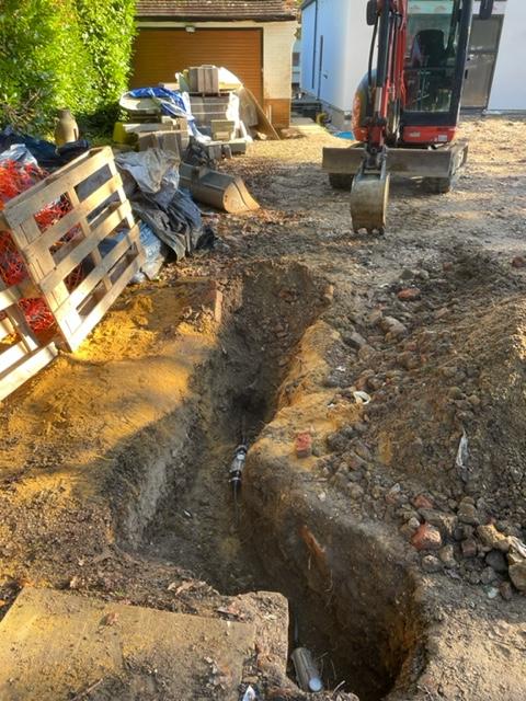
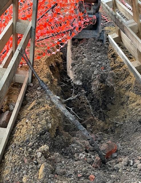
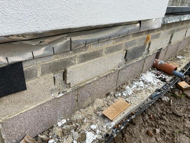
Pic of the repair, in the driveway facing the road, you can see the brick wall of the manhole on the driveway. The soil pipe entering the manhole should be another metre below the power cable. Now we know to connect in to the soil pipe we need to dig beneath the power cable. The second pic is looking back from the manhole at the road end of the driveway to the garage, the electric and gas enter the garage to the right of the door. We may be digging this trench by hand just to confirm without doubt the route of power cable and gas pipe. P.S. have hired a CAT scanner - as a minimum so I can say we used one if we did hit anything else. What I've learned from using it so far is: It confirms what you think you know already - i.e that the cable runs in a straight line between manhole and the garage It does not really confirm what you don't know already - i.e. the cable route for the short hop from the manhole to the road. I think maybe the cars on the drive had energised cables that were affecting to reading so will try again later.

-
Thanks for the digidat link @Dave Jones, looks like they only do water, and telecoms for my plot from a quick look but will have a fuller look later. As I now know where the electric and gas are at the garage end of the drive, and I now know there the electric cable is at the road end of the drive, we may just excavate by hand to expose the entire run. I know the locations of the sewer pipe and water and BT is overhead (until we duct it underground) so the risk now of hitting something should be low. Thanks for the tip on the digger bucket @markc - will look to swap with the hire company.
-
Ditto @markc This was one of the best £80 I spent on tools for my build. It rained on the dpm for our slab and we needed it totally dry for the tape to join dpm. This was brilliant in wet mode for that. Used it extensively in dry mode as a dust extractor for cutting wood and pir insulation also… https://www.toolstation.com/draper-20l-wet-dry-vacuum-cleaner/p63354
-
@ProDave @Moonshine My son was driving the digger. We were just digging a small hole down the outside of a brick built manhole - to see what kind of soil pipe we need to connect into. Basically the power cable came in a line above the soil pipe we were excavating then took a 90 degree turn just short of the manhole and then made its way past the manhole into the road. Will post a picture tomorrow showing the repair and the route the cable takes. There was no flash or bang as the digger pulled the cable out of a coupler. No one injured. No mention as yet what this might cost. The question is how to avoid this. I could hire a CAT scanner but not sure how effective they are. When UKPN came to do the survey before we disconnected the bungalow we ultimately demolished they really struggled to locate the cable entry point into the house- even with a signal generator. I spent a day digging a hole by hand but the cable was not there. They came back and with a very week signal from another CAT scanner we dug and located successfully. Who do you go to to get the route of all utilities across your property? And how accurate is this?
-
-
That is the key challenge I think as it will be cantilevering 70mm.
-
Thanks @Conor, where did you buy the EPS 100? When I search for EPS 100, EPS 200 etc. the results returned don't appear to be to this specification e.g. the product is 100mm thick, but nothing to say it is EPS 100.
-
Thanks @gravelld would be tempting to use PIR given I have some left over from inside, but somehow does not seem right below ground.
-
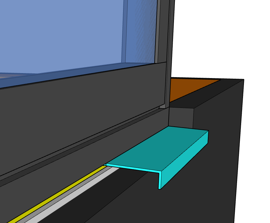
Yeah, I'm thinking a cill like this.... - in turquoise that oversells the insulation and whatever covering I'll use on the outside of the insulation. I did want to specify cills with the bifolds but the supplier did not have them as an option. I know of a company that produces pressings to order (they produced the cills for my Velfac order). I'll need to continue the external covering for the insulation into the reveal - which might be easier with render than other options such as slate. Not sure though on the need for a drainage channel - given the paving will be some way below the cill and will be sloping down away from the house.
-
Certainly not looking for a level threshold - most of the dropped thresholds are bifold. I have not planned the patio area in detail, current thinking is the paving surface would be around 100mm below the base of the window frame. Not so much that will require a step according to the regs.
-
Thanks @ETC that is intriguing and something I haven't seen before. I guess the advantage is that the vertical pipe can be terminated well above ground level so good in areas with a flood risk? Technically we are in a zone with a flood risk according to DEFRA, but with no historical records of actual flooding to properties.
-
From the outer face of the blockwork to the outer face of the render there is: 9mm OSB + 50mm batten + 18mm for Aqaupanel and thin coat render - so a 77mm projection. There is more information on the detailing for the outer skin in the link I shared just above this post. Yes there will be paving to approx 150mm below DPC.
-
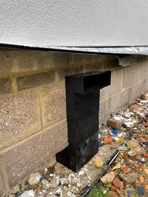
There will be 50mm insulation with some form of weather protection (e.g. render or slate tiles) fixed to the outside of the foundation blockwork.. The telescope vent will essentially be buried in the insulation. The finished ground level is approx 150mm below DPC. There is a separate thread on the external skin below ground here...
-
Interesting point of view here on use of EPS vs XPS below ground. I would have thought XPS would perform better, but maybe not?
-
Thanks @Iceverge the drawing is exactly how I saw it working - with the vent on the outside of the block wall in my pics. I like the way you have drawn the hole to be cut in a position below the centre of the course block above. Just cutting a hole big enough for the vent is a lot simpler than cutting in a lintel. It does make me wonder though why lintels are mandatory in other penetrations through the main load bearing skin of foundation blockwork e.g. the way a lintel is required for a soil pipe passing through the wall. Same could be said there that a block above bridging a gap of just over 100mm should be adequate - but it wouldn’t be I think according to the building regs.
-
Thanks @Iceverge your red line is correct - the bottom course of blocks is the void under the beams. So basically the telescope vent will need ideally to be inserted at the top of the bottom course of block - that way it will vent the underside of the insulated beam and block floor. Putting in a lintel as I had planned will move the telescope vent lower - perhaps even resting on the reinforced concrete ground beam. The separate pic I posted that shows the beam ends is actually a corner - the corner is in the left of the pic.
-
This is a section of the front elevation wall where the beam ends can be seen... ...but the plan was to install the telescope vents in the side walls.
-
More like the second image - except the infill blocks to the floor beams are EPS and extend down to the bottom of the beams. And I have no Marmox below the TF sole plate. Will have a read of your thread, thanks.
-
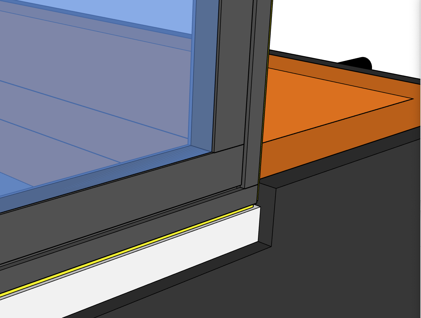
Any ideas on to to handle dropped thresholds? The drawing shows the foundation blackwork structural inner skin (orange), with the proposed external EPS/XPS (dark grey), the window set 39mm below DPC and a cast in situ concrete cill (white) below the window - the cill cantilevers about 20mm over the face of the blockwork. Don't want to extend patio slabs through the exterior EPS/XPS insulation to meet the cast in situ sill. But then how to cap the top exposed edge of the external insulation?

-
The time is approaching where I need to tackle a job I've been dreading - retro fitting telescope/periscope vents in 140mm concrete blockwork. The bricklayers left them out and in the rush to be ready for timber frame delivery I was reluctant to get the brickies to dismantle the foundation walls. Background is the floor is insulated beam and block - the pre-stressed beams run front to back of the house with many sleeper walls. I specified the telescope vents to go in the side walls. There are slots left in sleeper walls to allow ventilation from left to right. I have standard telescope vents with optional extension. I guess the 'right' way to do it would be: Identify a block in bottom course that is between timber fame studs. Use a mortar rake on and SDS drill to remove the mortar and remove the complete block. Replace block with concrete lintel at the top and two small section of concrete bloc to support the lintel. Telescope vent inserts under lintel between two smaller block pieces. Any observations please on how to do this safely and rapidly? Alternative vents such as small circular holes to be cut? Lintels are absolutely necessary?
-
Thanks for the link to the vid @DragsterDriver - I actually watched this series when installing, but did not get to this part. Hopefully it can be set after install. Edit: all you have to do is lift the window fully in top hung mode and the springs engage. No need to adjust from factory spring setting if a roof has a high-ish pitch - ours is 48 degrees. Will try later. Great videos by the way for anyone doing a self install. The videos linked from QR codes on the installation manuals are no where near as comprehensive. P.S. I found it interesting that in the videos, they fit a very small and light window - quite different with a large 3g Velux. It took four of us to lift and fit the sashes.
-
I’m hoping they do have a latching function in top hung mode but haven’t yet figured out how to engage it. Right now they’d need supporting with a stick to stay open in top hung.
-
I’ve got triple glazed Velux windows. They are not small windows and top hung. They are noticeably heavy and difficulty to lift in top hung mode - to the point where we use them in central opening mode but that means we need to keep the vent bar open. I’ve not encountered Veluxes before so can’t compare to the 2g option