Hilldes
-
Posts
375 -
Joined
-
Last visited
Everything posted by Hilldes
-
On the list of things to buy - the threaded rods - just normal or stainless steel?
-
Thanks will look for some sikagrout 111 and have the resin product from the video.
-
Spot on thanks! Btw it must have been really balls aching to cut those recesses in the footing concrete - really pleased I don’t need to do that.
-
Thanks, I know the bolts that go in the resin will not be the expanding type the framers used. What products please for the resin and structural grout - have not used these before
-
thanks @PeterW will order the padstones. So the resin fills the holes for the bolts and the grout fills any gaps between flange and pad stone. @PeterW @TonyT please could you recommend products to use?
-
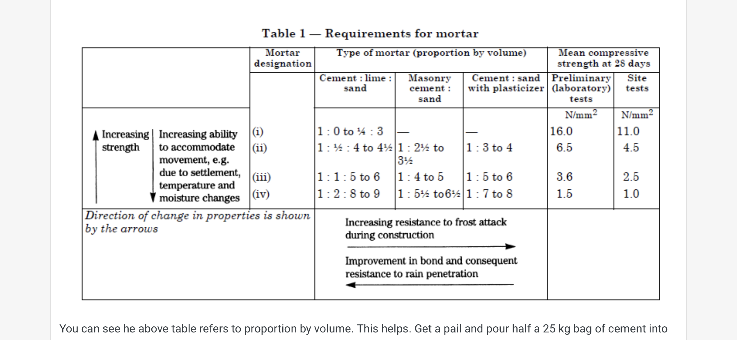
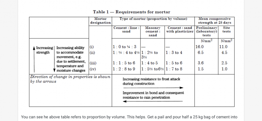
It does look like that from the photo although I did specify 1 to 3 or 1 to 4....
-
Thanks @Mr Punter (and @Conor) to identify the padstones required, would I need an SE to calculate or is there a rule of thumb? A padstone like this (Jewson 440x140x100 which is "is designed to ensure exceptional load bearing capabilities")? @Mr Punter Could you clarify please what you mean by support the column from elsewhere - you mean the padstone will need to extend more left and right in the photo than the flange of the steel?
-
Many thanks @Conor - the timber frame company had said they would use resined bolts before the build when I mentioned the frame would be sitting on blockwork and not reinforced concrete. The timber frame company actually supplied the expanding bolts instead to the erectors and the erectors used them without question. The blocks you see on the top course are 140mm(wide)x440mm(long)x100mm(high). I will look up the compressive strength, but they are a minimum of 7N/mm2. Assuming the flange at the base of the steel is 150mm x 140mm x7N/mm2, that should support 147kN - so should be sufficient for the loading???
-
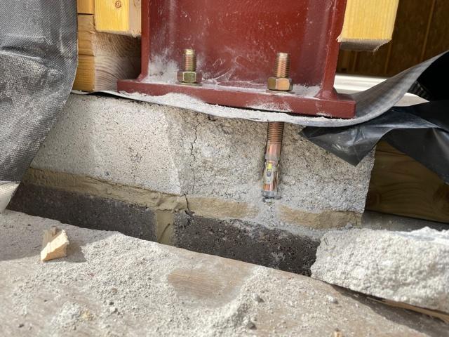
So the timber frame is now up. We have a number off steel columns that rest on the perimeter foundation blockwork - e.g. goal posts over bifolds and we also have portal frames supporting glazed gables. The timber frame erectors have bolted the vertical steels onto the foundation blockwork. In some cases the blocks receiving the bolts have visible cracks and in one case (see pic) the block has split. I'd very much appreciate thoughts on how to remedy. Timber frame company have said this does happen from time to time and they will ask erectors to apply a "structural grout". The timber frame erectors have said they would normally expect padstones to be used in foundation blockwork below steels. The column in the pic should support a load of almost 30kN (which I believe is about 3 tons). P.S. got BCO inspection tomorrow.
-
Please critique my HA design
Hilldes replied to Hilldes's topic in Networks, AV, Security & Automation
Has anyone played with the System Schematic feature in Loxone Config? Looks quite interesting in that it can overlay various objects on a schematic diagram and then display the status of the objects (e.g. switch input=on, relay activated to call for heat etc.). Video here. -
Please critique my HA design
Hilldes replied to Hilldes's topic in Networks, AV, Security & Automation
Thanks Jack, I have now ordered the Loxone terminal block sets - both interconnected and separate (latter very similar to the pic you posted). I did look at alternatives a while back and think I found some at RS or Farnell but were pretty much the same price as Loxone. I thought you had in mind some form of DIN mounted 'busbar' (like the neutral and earth busbars in a consumer unit) for a common 24v but I guess they would need to be split so one PSU only feeds one +24v busbar anyway. -
Please critique my HA design
Hilldes replied to Hilldes's topic in Networks, AV, Security & Automation
You mean if the savvy thief knew how much Loxone kit costs they'd want to steal it? ? I quite liked the design of the Loxone siren and drew on my 3d CAD model (a bit sad I know): Thanks for the info on the SSR relays will take a look and I already have a 24ch dimmer on order from Aliexpress. Thanks also for the link to the 5 core cable. I was thinking more like solid conductor cables such as mains cabling, but the flex is not a bad price and I guess if your carefull when stripping will be fine.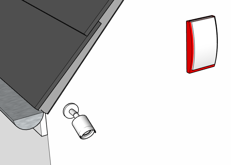
-
Please critique my HA design
Hilldes replied to Hilldes's topic in Networks, AV, Security & Automation
Thanks Jack, I'm about to purchase some Loxone banks of connectors like the one in the pic. Can I just check for the switches, your are feeding these to digital inputs - say supplying +24v from a PSU in the cabinet to the switch and when the switch closes this applies +24v to the Loxone digital input? .....so the busbar-type din rail termination would be a common +24v? Do you have a specific product in mind? I guess the alternative to keeping spare CAT6 pairs in a box outside the cabinet, just leave plenty of slack when pulling the CAT6 cable through then simply cut off unused pairs. To use more pairs later pull, through some of the slack in the CAT6 cable? -
Please critique my HA design
Hilldes replied to Hilldes's topic in Networks, AV, Security & Automation
Thanks Joth, good tips. I'm about to order the connector blocks and can envisage it getting quite busy. On the 24v dimming, where do the relays come in to this please? I was assuming you either dimmed or switched on/off (relays being the latter). Out of interest, would you have a link to a specific SSR product please by any chance?. I bought the alarm siren a while back and think Tree was the only option. P.S. thanks for the link to the Austrian poo shelf article. I made the mistake of reading it while I ate breakfast - but did add a wonderfull new phrase to my repertoire: "lay-and-display". I can now see even greater potential for automation ?. -
Please critique my HA design
Hilldes replied to Hilldes's topic in Networks, AV, Security & Automation
Not finalised DMX, but going to have play and see. What specific cable have you used please with 5 cores? For the option of putting the driver close to the LED strip, I guess the Loxone RGBW 24V Compact Dimmer Tree is an option, but it is still running at 24v along the Tree cable and you would need to be careful with what other devices the Tree cable is supplying power to. -
Thanks @Temp the tiles are concrete interlocking Marley Edgemere and Marley recommend ventilation. Will seek advice from the BCO. I'm fitting the mineral wool. I had specced Frametherm 32 slabs but just can't get it and high prices. May go for Frametherm 35 but I think I might also struggle to source in slabs and at a reasonable price. Will look at Kanuaf Omnifit.
-
Option 1 - will look for a membrane that can be in contact with insulation. With this option though, I'm guessing the membrane would not be brought up over the eaves ventilation? So any water ingress from the tiles will not run into the gutters? Option 2 - looks promising if I use mineral wool slabs and they don't push up into the cavity created by the counter batten. And the membrane can still pass over the eaves ventilation (or at least on top of the eaves rafter roll that comes with the eaves vent kit and then the rafter roll overlaps the gutter).
-
Yes with hindsight that might have been a better option. The timber frame is being erected at present and we have planning constraints on the height of the eaves and ridge.
-
Thanks, planning to go for slabs such as ROCKWOOL Flexi Slab in two layers between the 225mm rafters - 140mm + 90mm, so when held in by the PIR across the internal face of the rafters should not push upwards too much into the cavity formed by the counter battens.
-
Please critique my HA design
Hilldes replied to Hilldes's topic in Networks, AV, Security & Automation
Anyway...back to the serious business of this schematic. Let's look at some lighting basics such as what goes in the cabinet and what cable to use based on a few scenarios in the schematic: Non dimmed mains LED lamps - easy peasy, the DMX relays in the cabinet essentially are the switched live to the mains lamps. Using the most appropriate 240v T&E cable from the cabinet for the wattage/current. Dimmed mains LED lamps - the DMX dimmers will take care of this. Again, using the most appropriate 240v T&E cable for the wattage/current from cabinet to fitting. LED strips 24v non dimmed - the DMX relays provide switched live at 240v. The PSU (that drops to 24v) for the lights will be installed adjacent to the light fitting? The cable from the cabinet to PSU will be the most appropriate 240v T&E cable for the wattage/current. LED strips 24v dimmed - the DMX 24v dimmers...take power from one of the large PSUs in the cabinet and reduce current supplied to the 24v strip? For the cabling, ribbon cable won't be used between cabinet and LED strip, so we need to using something like mains cable but with 5 cores, so more cores than 3 core & earth? Assuming 'data' cables such CAT6 will not handle the required current. @joth @Dan F @jack @Rob99 -
Thanks, got the underside details sorted, will be 50mm PIR and taped of separate VCL. The bit I'm struggling with is maintaining a gap between the mineral wool between rafters and the breather membrane. Easy with PIR between rafters, but with Mineral wool, how to stop it riding up to fill the cavity between the counter battens.
-
Its my new build
-
Did not quite bottom this one in another more general thread. Does anyone have any specific experience please where all these are true: Roof space is habitable rooms with vaulted ceilings The rafters are full filled with mineral wool There is no insulation above the rafters There is no sarking (boarding) on top of the rafters If yes, please share how you ventilated the roof and the specific build up above the rafters.
-
Please review my foundation/floor/wall junction detailing
Hilldes replied to Hilldes's topic in Foundations
I though I'd post an update - sharing some lessons now we have the substructure complete, especially for anyone considering an insulated beam and block floor. To recap, this features an insulated beam and block floor from Milbank - make up from bottom (as specified in the BBA cert of the insulated floor system, which I believe is used by a number of concrete beam suppliers that offer an insulated beam infill option? Conventional pre-stressed concrete T beams with EPS insulation infill the full depth of the beam, A 150mm EPS top sheet across the top of the beams. Damp proof membrane Structural concrete topping to finished floor level (there is no conventional screed on top of the slab). Underneath all this are piles plus reinforced concrete ground beams. The foundation blockwork supports a timber frame structure with 140mm studs - and blockwork is 140mm wide to match the timber frame. Lessons: 1 making the blockwork the right height upto DPC. From my detailing, the final course of blocks to DPC would need to be 175mm high (not standard 215mm high for blocks). So the plan was to cut down the blocks lengthways so they were 175mm high. I hired a masonry bench saw with a view to accurately cutting down a large number of blocks - one course is >70 Linear metres so > 140 blocks. After cutting a few blocks with the masonry saw I abandoned this due to the time to cut each block and the fact the sliding table on the saw had no fence and I could see no way to attach one, so could not get accurate repeatable cuts. In the end I located two sizes of coursing bricks/blocks to make up the required height: W140mmxH65mmxL215mm and W140xH100xL440. These blocks cost me best part of £1K mainly due to the latter only being available in Cornwall and had high shipping costs (via Jewson). 2. Telescope vents (needed for any suspended floor) - make sure the brickies build as specced. I specced the vents to be in the side elevations of the house which ran parallel to the concrete floor beams. The brickies did not put them in because they said they normally go in the infill blocks at the ends of the floor beams - which is fine for a conventional B&B floor as they will vent below the inserted concrete blocks. However, this won't work so well with an insulated B&B floor where the insulation infills extend the whole depth of the T beams. Another problem with placing the vents here as the front/rear walls has dropped thresholds so there would be nowhere for the vents above finished ground level. I now need to cut in the vents in the side walls where I specced them to be. 3. Fixing UFH pipes in a concrete slab. It's not uncommon to bury UFH pipes in slabs, however most seem to attach them to the topside of steel reinforcing mesh. The BBA cert for our insulated floor system specified that the steel mesh should be at mid height in the slab and there must be min 75mm concrete above any "services". So our UFH pipes would need to go under the steel mesh. We opted for self adhesive clip tracks. They struck fine to the DPM. However when the pipes were clipped in they pulled the clip track upwards and the DPM with it - with such force that in places the pipes also lifted the steel mesh to the point it would have been protruding from the top of the slab. There was no option but to place some staples at the pipe loops to keep them down. I'm not sure what the alternative method of fixing the pipes would be, perhaps plastic pipe tray, but not sure how the chairs for the steel mesh would sit on these. 4. Ordering Readymix concrete. So my CAD model told me the slab had a volume of exactly 14m3 - which I'm sure is correct. So I ordered 14.2m3 - 0.2m3 for contingency as we don't want to be short when pouring a slab right? I also had not subtracted the volume of UFH pipes (almost 1km of 16mm pipe) and steel also in the slab which should mean we had even more ready mix left over. When it came to the pour we were indeed short of readymix and it was too late to order some more from the plant. By chance we had a bulk bag of aggregate, a mixer and many bags of cement, so we mixed some more conrete - all of the bulk bag and we were still short. We got the last couple of barrowfulls from our spoil pile where the pump had been emptied. Lesson is that you need to allow for vibrating which we did that allegedly gives a better finish and stronger concrete but reduces the volume of the concrete and also allow for the waste in the pump (substantial) and readymix truck. 5. Generally very pleased with the insulated floor system - very easy to install and all quantities calculated correctly by manufacturer. Beware the insulation comes by default on an artic due to the sheer volume - we had to pay for the shipment back to warehouse then back to us on two smaller vehicles when the artic driver refused to enter our road.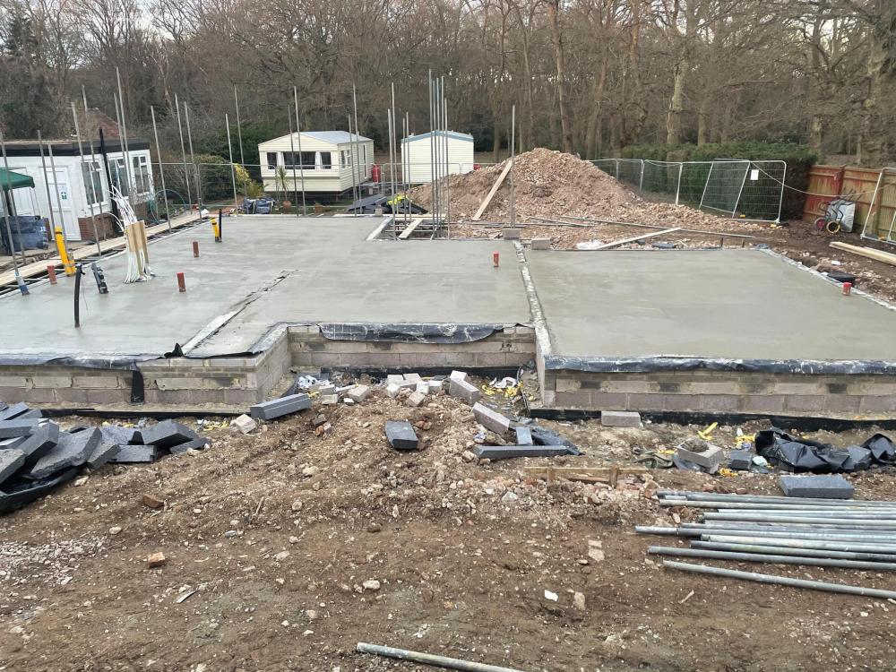

-
Automated lighting and lamps
Hilldes replied to MLR1907's topic in Networks, AV, Security & Automation
Can still buy them... 5A round pin socket