andyscotland
-
Posts
638 -
Joined
-
Last visited
-
Days Won
1
2 Followers

andyscotland's Achievements
Regular Member (4/5)
271
Reputation
-
I agree with @-rick-, I'm not sure 5A sockets are that useful these days, there's no guarantee they will be where you want them/controlled from where you want them to be over time (or for a future buyer). I think the most flexible/future proof setup is: * As many standard 13A sockets as possible, including in places you might logically want a floor lamp (corners of rooms etc). * Each fixed lighting appliance (counting e.g. a run of downlights as one "appliance") and lightswitch wired individually back to a central e.g. Wago box accessible but out of sight in a plant room / cupboard etc. Even for two-way etc switching, each switch goes to the wiring centre and then back out to the other(s). Then you can very easily: * Fit smart drivers at your wiring centre, controlled by any existing switch or from e.g. an app * Replace one or more light switches with a powered scene controller / smart device (as you're just reconnecting the existing cable to carry phase and neutral instead of phase and switched phase) * Put freestanding lamps anywhere you like, fitting a smart driver either in the lamp itself or a discreet/suitable box between lamp and plug, controlled by physical lightswitches/scene controller/app/whatever as above. * Change any of those decisions and any of that kit at any time in the future. * Rip out all of the smart stuff and just reconnect the switches and lighting points directly as "dumb" wiring at the wiring centre without opening up individual accessories (no risk of damaging/marking paintwork etc). May mean a bit more cable than traditional loop in/out, but for the flexibility you get I think it's more than worth it.
-
I'd argue that to create a safe zone it should really be an actual mains accessory or junction/cable box. If it's just a battery powered unit or a blank plate, there's a risk someone pops the lid, sees there's no cables going out of it, and assumes the walls beside/above/below are fine to drill. I think it'll be very hard to fish along a cable tray, and even if you could as others have said you can't then fix the cable to it at intervals so it will not be properly supported meaning a) mechanical stress and b) could droop below the safe zone. Conduit or enclosed trunking would be best for fishing, but obviously you'd have to cut a new hole in the bottom if you want a new vertical drop out of it so that would mean opening up that bit of the wall at least. I'd agree with @ProDave the best option is to run all the cables at socket height with at least one socket on each wall. Like @-rick- says, if you run a 50mm batten horizontally on every wall aligned with the base of your sockets, with a gap above it, you have formed a natural "cable tray" / trunking out of your wall construction without any extra materials. You should be able to fish new cables horizontally along that batten, drop vertically down to it from above, etc, with minimal disruption. So long as you only use max 35mm backboxes there will be plenty of space to pass cables behind them, you could just about get behind a 47mm backbox (as 12mm of that will be in the plasterboard). If you want a second zone for data cables then run another batten above or below (depending on whether you think you're more likely to need to add vertical runs for mains or data).
-
is there a better kind of roofing / cladding batten?
andyscotland replied to Alan Ambrose's topic in Building Materials
BBA are an authority that certifies building products (the most common/accepted one, but technically speaking not the only way to prove that a product meets standards). UKAS are the authority that certifies anyone that wants to be an authority in testing/certifying/calibrating in any market. They basically check that organisations have the right governance/systems/processes in place to be trustworthy. So e.g. you might have a bolted structural fixing that has a BBA certificate, and install it with a torque wrench that has a manufacturer/tester calibration certificate from some other UKAS accredited organisation. It looks like the BBA issue is a paperwork technicality - likely BBA just need to update some documents or it may be that their corporate restructure means they're technically speaking a different legal entity and therefore need to be reaccredited by UKAS even if nothing much "on the ground" has changed. So I'd imagine it will be resolved before too long. -
UFH layout in odd-shaped space, on overlay panels
andyscotland replied to andyscotland's topic in Underfloor Heating
Also just to add, if I drop the delta-T to 3 degrees, that looks like it might still work - flow rates for each circuit would be 1.6 / 1.7 / 2.0 litres/minute for a total of 5.36 litres per minute. Which I think should be OK? Am I right in thinking that ideally the lower the delta-T the better (so long as it still produces enough heat output)? -
UFH layout in odd-shaped space, on overlay panels
andyscotland replied to andyscotland's topic in Underfloor Heating
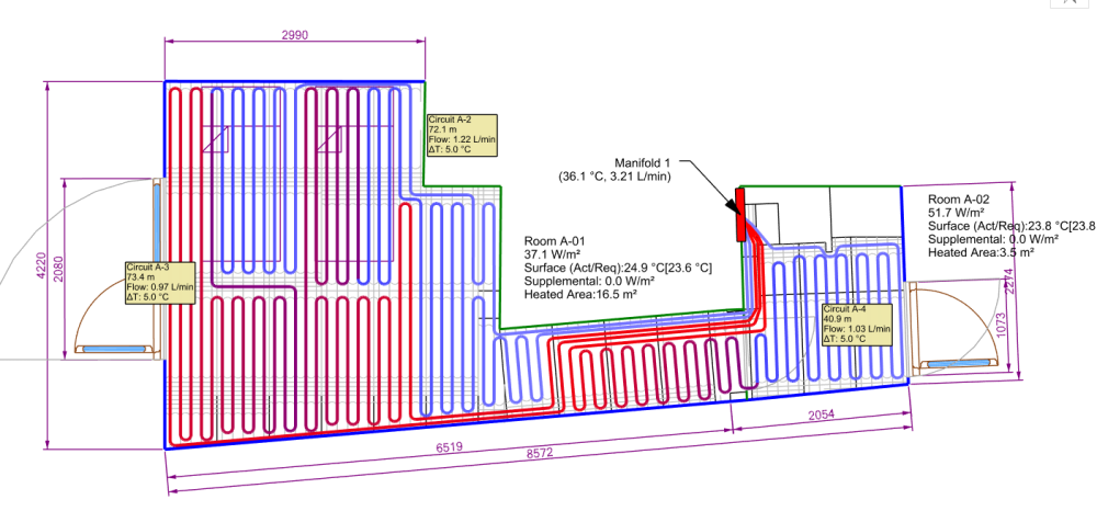
OK, I have properly modelled the space insulation / heat loss etc values in LoopCad and set it to a delta-T of 5 degrees (I'm not sure why it had defaulted to 11 degrees originally, but that was very helpful advice @JohnMo, thanks!). I also worked it out in terms of where the actual turns / channels in the UFH panels will be, to help figure out the best / easiest routes. I now have: And a circuit temperature diagram that looks like: Does that look vaguely sensible / viable? In my head this should give a fairly even temperature across the open floor area in the bedroom. It also brings a bit of the utility room / porch loop into the bedroom (and takes the hot water there first) - on the basis that the utility won't need as much heat and this keeps the bedroom loops a little bit shorter (I've seen advice that around 70m is a good limit for 12mm pipe). Any opinions welcome! Thanks
-
Recessing elec conduit in floor for floor plugs?
andyscotland replied to Great_scot_selfbuild's topic in General Flooring
Technically speaking there are no specific requirements for cables in a floor apart from where they're passing through joists. The 50mm depth or steel plate (or other mechanical protection) is to protect against damage by fixings into the joists. Between joists, or in cases like this where there are no joists, there's just a general requirement that the cable is installed so that it isn't likely to be damaged by contact with the floor or its fixings. That's a risk assessment you have to make based on the nature of the building/installation. So if e.g. you have a floating floor over the PIR then there's fairly limited risk of anyone fixing down through that. And the PIR itself and the space within the duct will provide a fair bit of protection against the cable being crushed by weight on the floor. So I'd think steel plate would be overkill, especially if 50mm or deeper. SELECT have quite a good guidance note on cables concealed within building structures https://select.org.uk/common/uploaded files/Technical/FreeDownloads/30270_PG_InstallationOfCables.pdf -
UFH layout in odd-shaped space, on overlay panels
andyscotland replied to andyscotland's topic in Underfloor Heating
Sorry, I should have made that clear at the start. -
UFH layout in odd-shaped space, on overlay panels
andyscotland replied to andyscotland's topic in Underfloor Heating
Thanks, that's probably fair. I knew from the beginning of the project I was committed to the overlay panels due to the nature of the conversion/buildup I have. I did then more recently provide details including u-values to the supplier but it's only now that I'm wondering how good their design really is... Ok I will try that and see how I go. Although in my head it's safer to have spacing tighter than I could get away with (even if that means 3 loops) because it's easier to reduce output (by dropping flow rate/flow temp/cycling) than it is to increase it if the building turned out to be colder than the model and there's not enough pipe in the floor? The manufacturers I've looked at all seem to advise 120mm spacing for the 16mm overlay panels with 12mm pipe. But as you can tell this part of the project is definitely not my area of expertise/experience! -
UFH layout in odd-shaped space, on overlay panels
andyscotland replied to andyscotland's topic in Underfloor Heating
OK I have come up with another layout that (just) stays within the 80m length constraint I have, but separates the loops for the bedroom & utility so they can be balanced more easily. It does mean a bit less heat in the utility room corridor, but that's maybe not a bad thing, and it allows me to get the flow & return pipes much further apart. Any thoughts welcome!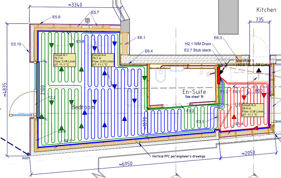
-
Recessing elec conduit in floor for floor plugs?
andyscotland replied to Great_scot_selfbuild's topic in General Flooring
I would put them as deep in the PIR as you can. What you've described doesn't quite fit any of the standard installation Reference Methods in BS7671 but from first principles, surrounded by insulation and overlaid by heating pipes is about the worst possible case. Slightly counterintuitively on a heated floor "not covered by thermal insulation" really means putting it on the cold side of the insulation e.g. at the bottom. If you can get the conduit touching or at least nearest the concrete then I'd say it's similar to Reference Method A. Be aware that the rating for 2.5mm flat twin & earth in method A is exactly 20 amps at an ambient temperature of 30 degrees. Depending on what temperature you're heating the floor to, and what temp you expect below the beam and block, your ambient at the conduit might be above 30° - you might want to model that temperature gradient to check (or design the circuit to operate at higher temp e.g. by using a 16A radial). -
UFH layout in odd-shaped space, on overlay panels
andyscotland replied to andyscotland's topic in Underfloor Heating
Thanks @JohnMo Ah yes I was planning to once I settle on a layout - bit of a LoopCad learning curve and the walls etc are not in its standard constructions so was going to come back to that. Unfortunately I already have the kit and the pipes are supplied as three 80m lengths so I don't think I can delete the red loop entirely. But I could maybe use it just for the utility and cover more/all of the bedroom corridor from the blue & green loops. Agreed - although it also serves as a hallway between the house & bedroom, and between outside & bedroom, so it maybe needs to be a little warmer than a true utility room. -
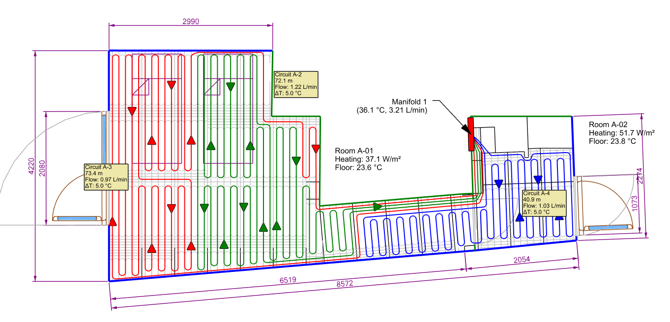
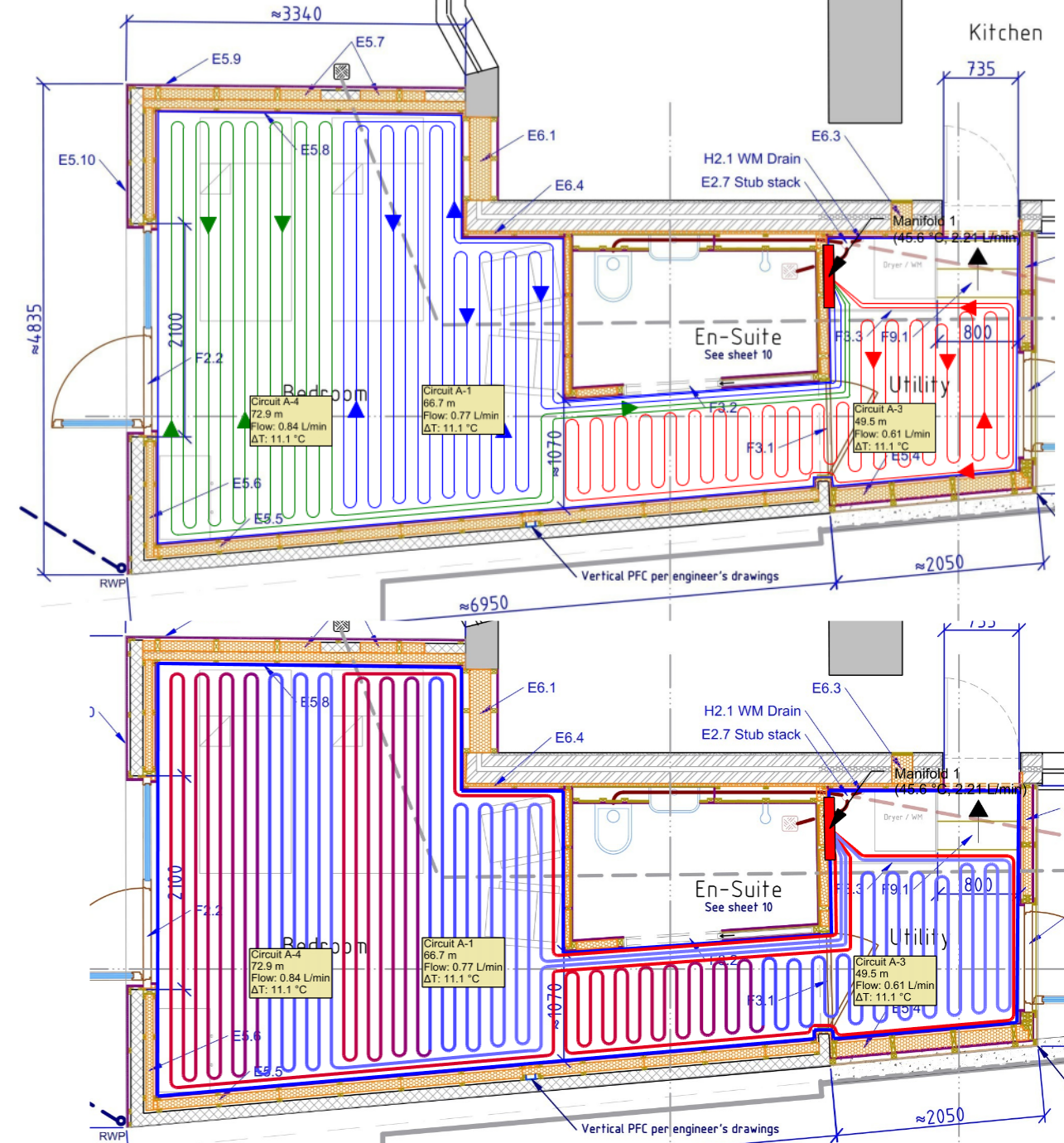
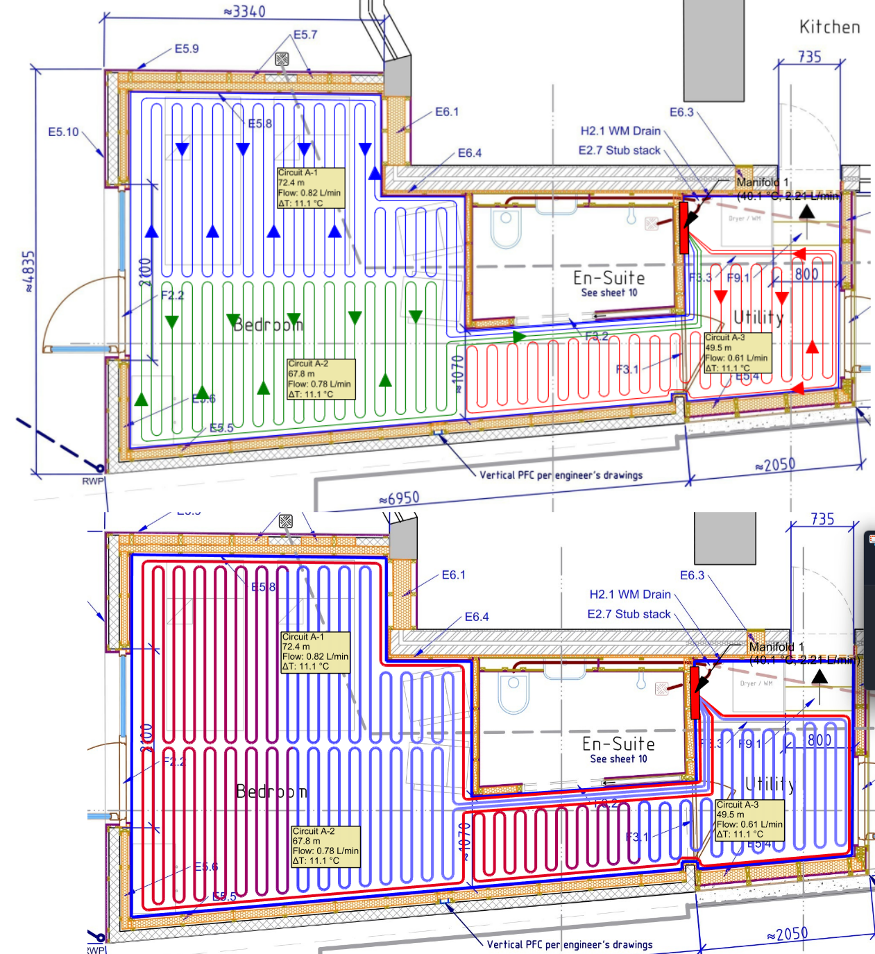
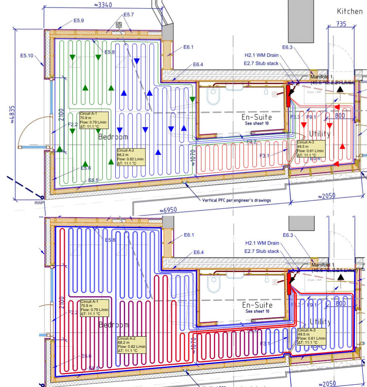
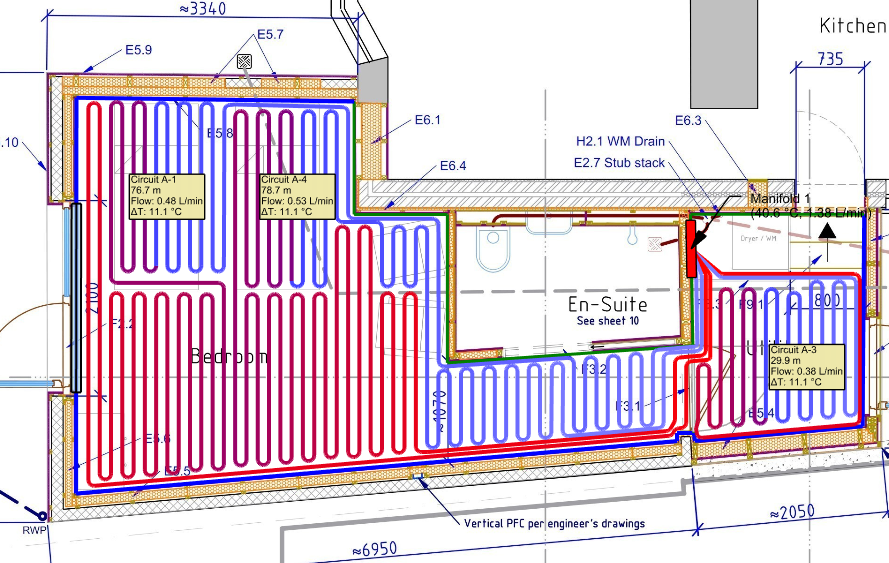
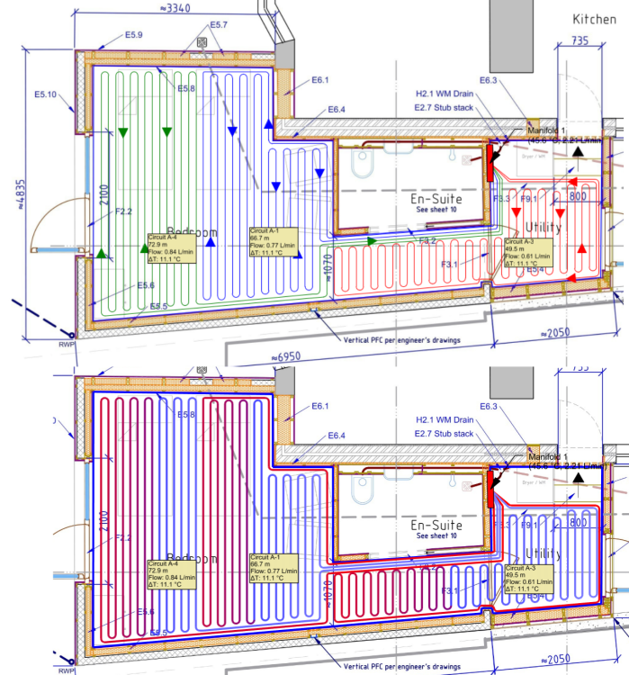
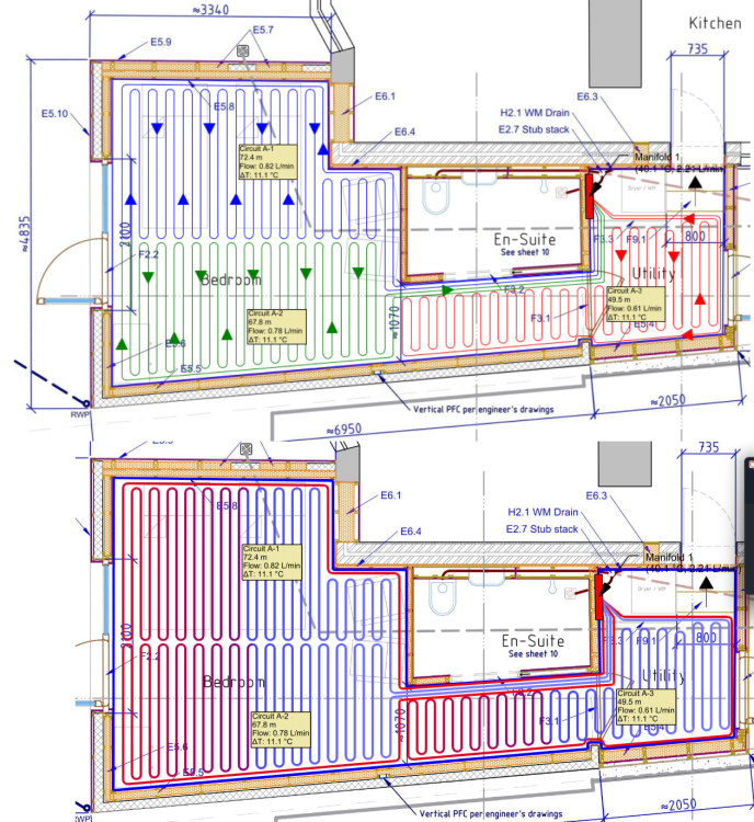
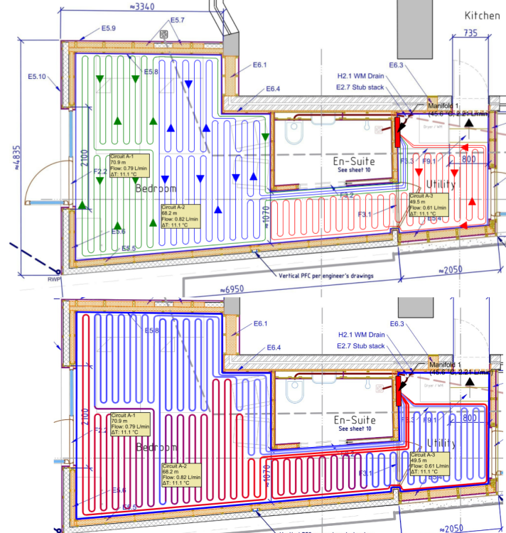
My extension has finally reached the point of laying the UFH and flooring. I'm using the pre-routed overlay panels, so am tied to 120mm pipe spacings and ideally as many as possible of the pipes running in the pre-cut grooves / round the pre-cut bends. I wasn't completely happy with the layout my supplier did. They don't manage to get to several of the perimeter walls until quite far into the loops, and they've bunched several flow & return pipes very close together along the edge of a corridor which in my head means the return will have taken quite a bit of the heat out of the flow before it ever gets into the rest of the space. I can't avoid them running near each other, but I think I can at least space them out a little bit. So I've been trying to draw alternatives with LoopCAD, and I'm not sure which is best - or if there's a better option... I've shared 3 options below, as both the schematic and LoopCAD's model of the circuit temperature along the length. NB: The ensuite will have electric UFH within the tiling, so doesn't need to be part of the wet system. The manifold location is locked in and can't change. I haven't fully modelled the space in LoopCAD, so ignore the flow & DeltaT figures on the circuit labels. In case it's not obvious, there's a door between the utility & bedroom, but no door where the corridor (past the en-suite) opens out to the rest of the bedroom. Option 1: Closest to what the supplier did, but with some tweaks to take the flow pipes round the walls first. Probably the easiest to install. I'm a little nervous that the floor will feel unevenly hot as you walk the length of the room (e.g. if you get out of the far side of the bed and walk to the ensuite). Option 2: Less "stripey" heat than option 1, and more of it near the window & far wall where heat loss will be higher. Downside is that there's possibly an even more noticeable change in floor feel as you go from the bedroom to the ensuite corridor. And most of the blue circuit is below the area where the beds will be. It's also a lot more faffy to install. Option 3 I think I like this the best. It gets most of the hottest water into the open floor area, with the area under the beds on the return half of the pipe. I think that should give quite an even temperature / gradient across the area of the bedroom & corridor where people will be walking. It will still be more of a faff to install than the simpler option 1 - though I'll hopefully be able to get the spacings about right to mostly use the bends & link channels that are already formed into the boards, but I think potentially worth it? Would love to hear your criticisms / advice!
-
It gets reviewed, but has to be negotiated with the King's Treasurer and there is no role for Parliament to have any say in what it is. But your Presidency also has significant executive functions (and staff to support that) that are already covered in other parts of our budget. Going by your document (and my rusty French!) that Presidency also includes things like security, which we cover directly out of Met Police and similar budgets and is not part of the Sovereign Grant. In any case my argument is not that we should return to a republic - at least, that's not this argument 🤣. I simply think that whatever our constitutional arrangements: * All revenue from public assets should flow to the Treasury * All expenditure from that revenue should be controlled by a Parliament with the freedom to decide how best to allocate the available budget based on the public services they think are important and the costs of delivering those. And specifically for this thread, Parliament should allocate income from selling offshore seabed leases for windfarms (& other income from renewable generation on public land) towards investing in onshore grid upgrades & other aspects of the energy transition, rather than adding all those costs to our bills.
-
Those summaries make it all sound very reasonable, compared to my (perhaps deliberately provocative) wording, but they are somewhat misleading. The net profit from the Crown Estate does indeed go to the Treasury. Net profit is of course an interesting concept - an amount of scope to spend money on nice things out of revenue before you get to that figure. The AI summary then mentions the Sovereign Grant "to fund official duties". Sounds fair enough. Except what it doesn't mention is that - unlike almost any other public service, where you start by costing the "official duties" you can justify funding - the Sovereign Grant is a fixed percentage of the net revenue. If the Crown Estate makes more money, the royals do more royalling (or more expensive royalling). There is no mechanism for us to decide that actually we would like the same amount of royalling as last year and to spend the bonus on something else. In fact it's even worse than that. If the net revenue goes down then the Sovereign Grant is set the same level as last year. So we get the same amount of royalling as before, whether we like it or not, and make cuts elsewhere. And this whole situation has been made worse by the unexpected windfall in seabed leases for windfarms (which we are ultimately paying for in our electricity bills) which has delivered close to £500m a year in extra profit. The royals have kindly agreed to reduce their Sovereign Grant % a bit as a result but are still getting an extra £45m this year - again, paid for by us, whatever the mechanism those £ use to get from our pocket to their expenses. No other part of the public finances works this way and IMO regardless of any opinions on the monarchy either way it is bonkers that this is how their budget works.
-
Absolutely. Many of the things that are wrong with our energy system (not all, but many) are down to a lack of will. It's not even like it's an ancient tradition. The system until very recently was that the Treasury got all the revenue from the Crown Estate (like any other public asset) and gave the royals a budget for their public duties based on what they could justify (like any other public service). It was only in Cameron's time that that flipped to them giving us a share if we went cap in hand and persuaded them to hand it over. So it's even worse - there was the will to revert to a feudal system, but not the will to change it back.