
Radian
-
Posts
2586 -
Joined
-
Last visited
-
Days Won
15
Everything posted by Radian
-
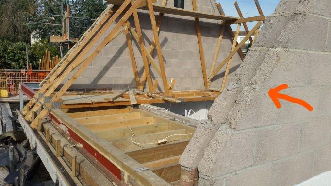
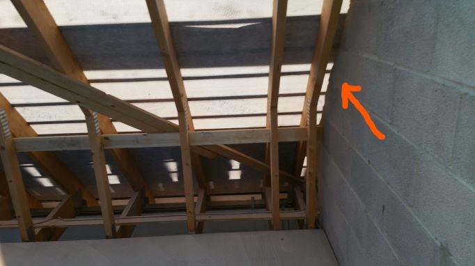
Just poked phone between truss and wall (where the orange arrow is above) to snap this photo: The edge of the outer sheet of roof insulation is visible (100mm Kingspan). There's quite some gap between the edge of the concrete blocks and the underside of the breather membrane because the roof pitch was altered by a couple of degrees. If I could make a right-angled lance to inject the squirty foam I could aim it at the insulation and build off it to close the cavity as well as making a continuous seal - although I can imagine it getting out of control and contacting the membrane. I guess this could also be a possibility if I drilled injection holes and squirted through those instead. But what harm, if any, might there be in getting foam on the membrane?
.thumb.jpg.d8ae2c391e81ffade289f2e9af07b803.jpg)
-
I have to say I've only had trouble when using Varilight dimmers in the past. Not greatly impressed. Have you checked their troubleshooting page? There are a couple of mentions for random switch-ons but only seems to be to do with remote programming which I don't think is relevant to your issue.
-
Unless there's a better solution, this will have to be the answer. My only worry is verifying that the fill is continuous - I will try my inspection cam to see if I can get a view from around the end of the wall. Yeah, like having a fireplace chimney in reverse. If I do go down the squirty foam route as suggest by PeterW it wouldn't be too much extra to run horizontally at floor level. The door opening already closes the cavity in the middle 0.8m so I could, in theory, isolate the complete triangular wall. Then when I complete the store area I would have continuous insulation ?
-
It's an empty cavity. But it was just a garage built 23 years ago. The problem with doing anything with the occupied half is it's all finished and furnished now. I would therefore like to do any remedial work in the unused half. There's already a doorway in the gable so the plan is to partition off a further 2m to make a store room that will be insulated. At least this should reduce losses through the cavity.
-
Can anyone suggest how I can retrospectively close the cavity of the internal gable inside this building? Here it was - at the perfect time to close it... Same location from the inside - after it was too late: The gap between the attic truss and wall is too tight to work-in a typical plastic/foam cavity closer while making sure it's a good seal. This last photo was taken above the car parking side of the garage so is effectively permanently open to the outside air and it's obviously leaking air into the occupied side like crazy. I can work insulation in between the truss and wall but the cavity would remain an open route to air movement into the insulated zone on the other side of the wall.
-
I'm looking with suspicion at that “S-LINK” connection. I take it you have installed some supplementary controllers as per your diagram? If so, and the cables for the hallway lighting and supplementary controllers are in close proximity then it may be capacitive coupling. They do say: Which implies a certain degree of sensitivity on this signal line.
-
The green light is labelled as "ON compressore" I also wonder where it's located!
-
@ProDave I think he's pulled out connector D - pins 1,2,3 go to R1 and 4,5,6 go to R5 It's looking like the IR breakdown is on the wiring going between KA6/2 and the mating socket D - probably the orange wire, as the R5 connections are switched by KA4 which is still in circuit without fault. Edit: crossover post missed your comment - so we're both thinking the green light?
-
Did that plug go into a socket labelled D ?
-
Another KA6 shown `on the schematic powers a green light (compressor on) but it doesn't differentiate between KA6/1 or KA6/ 2. So far as I can see, three KA6 contact pairs separately switch on A5 (compressor starter), GN1 (green compressor on light) and R1 (crankcase heater) KA6/1 has been left in so that must have the compressor starter on it. KA6/2 has been removed and we know it connects the faulty heater. If the green light also comes on with the compressor then that will be on KA6/1 if not then its on KA6/1.
-
So if that's the heater and its insulation resistance is compromised what are you going to do? Personally, I would use an IR test meter to measure between each black wire and earth, make a note of the readings then power it up from a non-rcd protected supply, leave it a day then test again. If it doesn't show a higher resistance then there's not much hope and it could be a question of finding a spare. Or just leave it unconnected.
-
I see you put up a photo of a piece of plastic mentioning the crankcase heater but it's not any of the wires in the previous photo. Where can it be?
-
No worries. Because you were buying from RS I guessed you might be up for doing a bit of electronics ?
-
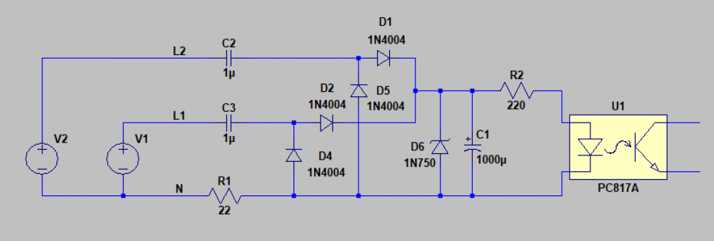
If you wanted a much lower cost solid-state solution using an optocoupler you could knock up a circuit like this: C1 can be any low voltage electrolytic e.g. 6V, C2 & C3 need to be 400VAC types. R1 ought to be 1W, R2 1/4W and just about any sensitive opto should do if PC817A hard to find. D6 is a 4.7V 1/2W Zener. You would need to be confident in constructing a mains powered circuit - I only suggest this if you have the appropriate skills! ...And I'm assuming the volt-free input is low voltage control!!!
-
Why have you shown the relay coils in series with the lights?
-
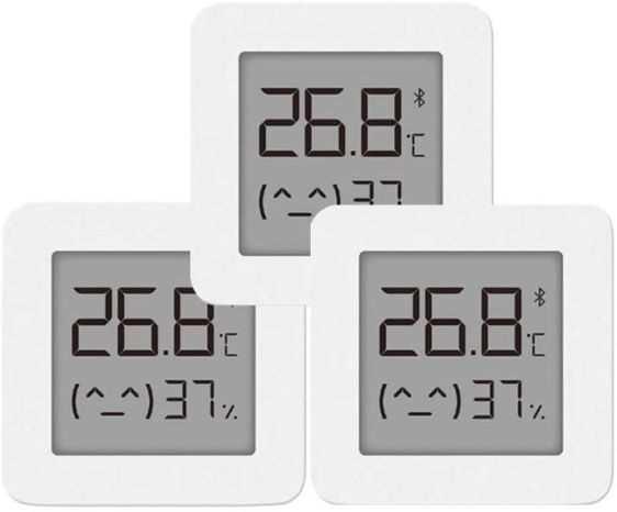
Thanks, yes, I've used the online data before but for this particular rig I'm using modified Bluetooth sensors logging into a DB along with various other indoor sensors. I'm really quite chuffed with them as they're only £7 each and there's a Hacked firmware for them that allows the data to be transmitted using the BLE Beacon function. This can be intercepted using an ESP32 and logged over WiFi. This means you don't have to go anywhere near the smartphone app they were originally intended for.?
-
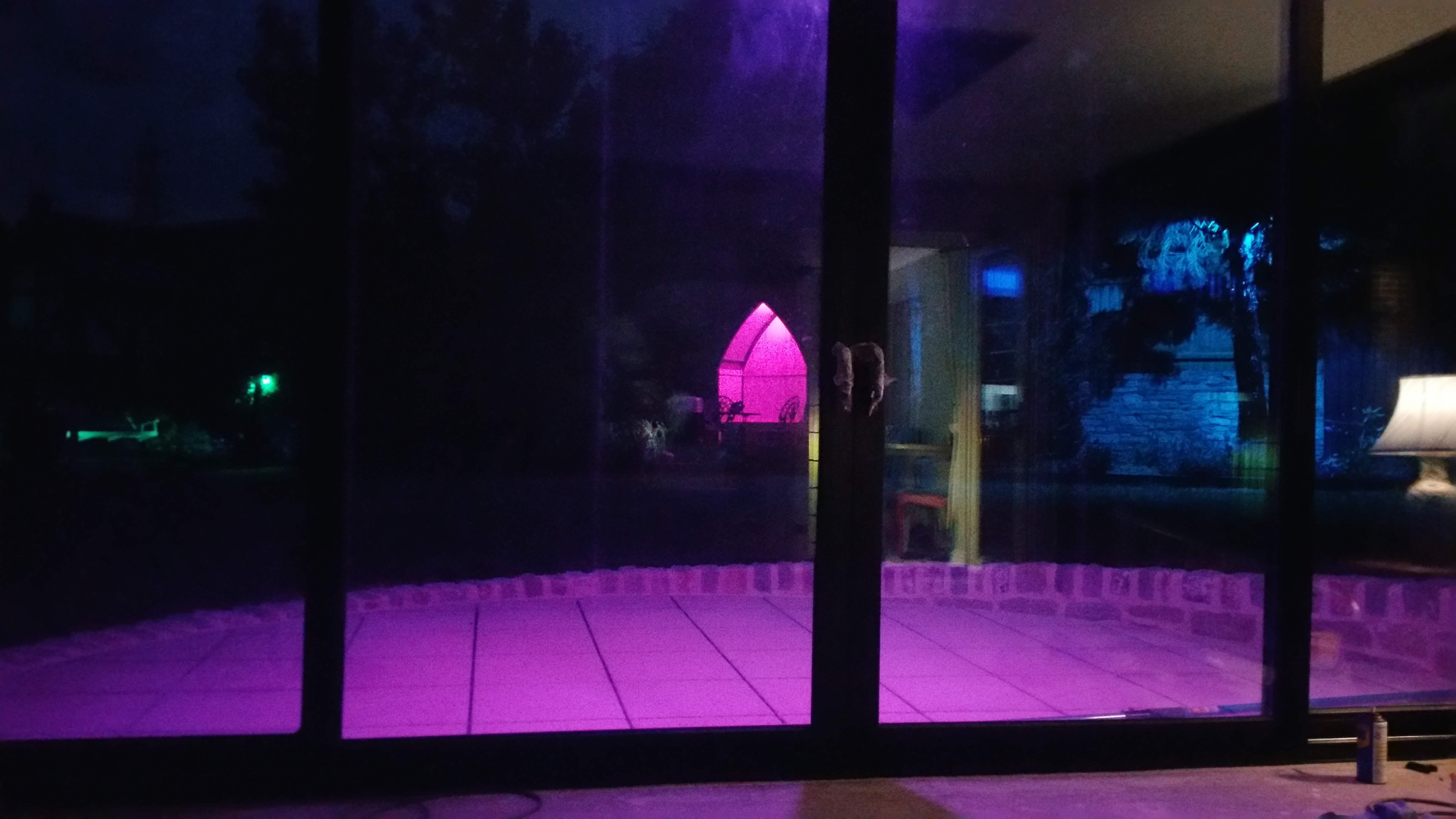
Yeah, the biggest delta so far has only been 8 degrees. If I was using the place I would crank it up inside but I'm otherwise engaged at the moment. On the other hand, Nature may intervene for me in the coming months. Not much of a problem on the ground floor with glass facing NW/NE but it did get uncomfortably hot for a week or two upstairs this summer.
-
And to think, I just finished screwing half a kilometre of recycled roofing battens to a block wall to act as a rain screen. Should have kept it for the fireplace.?
-
Just wait... and for no particular reason, the price of new PV installations will now start to climb - despite the continual fall in material costs. ?
-
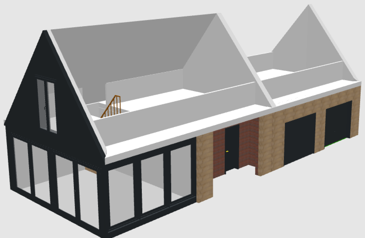
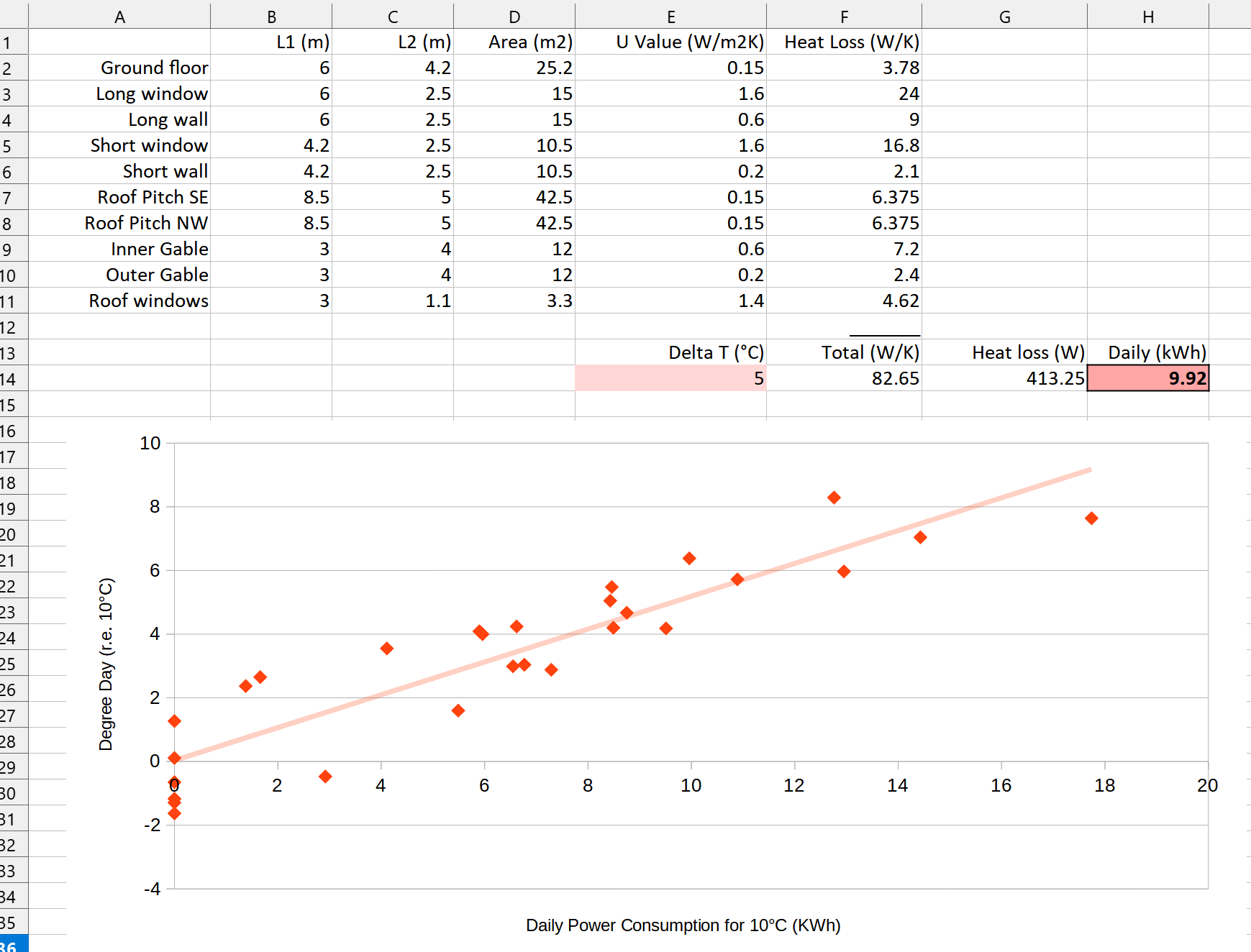
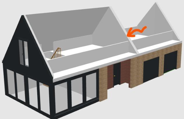
My recently built garage/workshop extension looks roughly like this: The new glazed pavilion and floor above has been added on to our original workshop/garage. The intermediate gable was demolished at first floor level to create one large room above. Regrettably the insulation levels are to building standards only, and no heating has yet been installed. I did put in a UFH loop in the ground floor screed in preparation though. Unfortunately this was all planned and constructed when energy costs were nothing like the major issue they are now. Now I'm trying to figure out what kind of heating to put in to make it usable all year round, so I've been collecting data on the actual thermal performance comparing it with some rough heat loss calculations and I'm not sure if it all stacks up. All I've done is very crudely worked out the fabric heat losses (the original cavity walls are more like guesses) and put in a 2kW digitally controlled heater set to 10C, monitoring daily power consumption vs. mean outside temperature. As shown above, the loss calcs suggest 10kWh for a 5C delta. The actual data agrees with this almost exactly but I'm suspicious! After all, there's no account taken for air exchange and there's been no other heat input during the monitoring as the place is currently unoccupied. Should I trust this experiment and base my heating decisions on it?


-
Would be interesting I agree. However, for fault finding how about @Chriswills getting one of these OK, so it's xmas cracker grade Chinese instrumentation but £43 not £1K for a proper megger. I can vouch for the fact these usually do work well enough to predict if an RCD will trip or not.

-
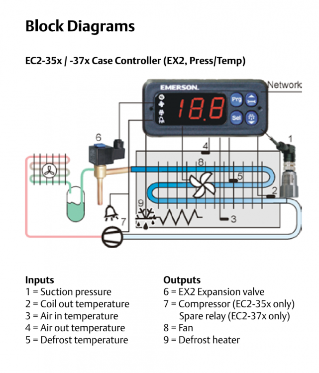
This doc from https://www.orionairsales.co.uk/ may be relevant but its a bit light on wiring detail
-
Maybe, but I expect the reason for the IR breakdown is cyclic warming/cooling pulling a tiny amount of moisture laden air into the housing - after all, unless there's a refrigerant leak, no actual fluids are present. If it's that marginal then powering the heater on for a day or so could restore it. Both KA6 relay coils are in parallel so the crankcase heater is designed to be energised all the while the compressor runs so should handle continuous energisation.
-
I'm guessing it's not a serviceable component, but contained inside the welded steel enclosure. Any attempt to fix it would be conducted from the external wiring. The heater live and neutral would need to be identified and a temporary connection made to them ideally using an isolating transformer.
-
Inside the compressor housing - in the crankcase, as described in the schematic you posted.

.jpg.fbc7448f6cf21e231c2b94c6e707ed1b.jpg)