Lilly_Pines
-
Posts
35 -
Joined
Everything posted by Lilly_Pines
-
Fire resistance of the buildup as drawn might actually be marginal? With a conservative charring rate of 1mm/min, and the tiles sitting on 25mm of beam on each end, fire damage would reach past the part they sit on in less than 30 minutes. Assuming the charred wood cannot carry loads, there could be the possibility of the tiles and pugging falling off and exposing the thinner structures after 30 min. Covering the beams entirely with the tiles and using 2x2" battens on top might be an alternative with better fire resistance, but even 30 minutes should satisfy Approved Document B so this may not be an issue in practice.
-
Now that I think of it a bit more, 80 kg/m2 might be excessive and a specification in the range of 40kg/m2 might be perfectly sufficient for airborne insulation in the same dwelling, so the 33mm afforded by 2x3" battens would be a bit thinner and cheaper.
-
It is not, with 30mm thick tiles and 89mm battens the space remaining between the tiles and the floorboards would be 59mm because the tiles sit on the edges of the secondary beams, between the battens. Reducing the battens to 63mm would leave 33mm. However, with such a thin layer I'd start to get concerned about the acoustic implications; I modeled the pugging after acoustic products like Hush-Fill (except without the price of slapping a proprietary label on a bag of tiny stones, as regular coarse sand/fine gravel/whatever should do pretty much the same job for less cost), so the dead weight is an intentional feature and cutting the layer thickness would obviously cut the weight as well. If the pugging being loose is a problem for the UFH, the pipes could perhaps be fitted to the tiles with more solid material and loose fill added on top. Insofar as the dead weight itself goes, my rough calculations are giving 7.4mm deflection for a 5m long 20x40cm scots pine primary beam loaded with 5,000kg uniformly over its length, equaling roughly 600kg/m2 if the beams are at 1.7m centers, or 5.2mm deflection for a 4m beam loaded with 1,000kg/m2. The secondary beams in turn are deflected far less due to their shorter length. 80kg/m2 is peanuts compared to the capacity of this floor design, which is intended to be excessive for any normal residential specification.
-
Performance considerations: Unglazed terracotta tiles aren't amazing acoustically, but the grid structure of beams should help diffuse echoes. Alternative materials with good acoustic and aesthetic properties could be nice, but I'm not sure I know of any that work here. Woodwool boards most likely require backing structure, and don't necessarily look great. Hempcrete seems like a pain to cast within a ceiling like this if permanent shuttering isn't used, and permanent shuttering means woodwool. Cork again requires a backing structure, and may look weird in colours other than brown. The UFH would heat and cool the tiles significantly more than the floorboards. That is fine because softwood boards are quite insulating already so a large amount of heating is not needed for good foot-feel. Cooling is limited by how much the wooden floorboards can tolerate. Thick wood has okay thermal capacity but is not amazing. A timber-concrete composite with an oiled earth finish would probably be significantly better at dealing with excessive solar gain, with greater thermal conductivity to quickly pull excess heat away. Airtightness layer would be on the exterior of the ring beams, so the floor structure doesn't matter for it.
-
Construction time considerations: Once the structural beams have been laid, a temporary floor can be placed across them. Apart from plastering the walls of the room below, there seems to be no further need to work at heights as the ceiling tiles and any fixtures, penetrations, etc. can be installed from above. Fixtures in the ceiling can either be attached to the beams, or they can be attached through a hole in a tile to a cross-batten placed above it to take the load. Because the 2x4" battens are mainly to act as spacers for the floorboards above, cutting them for pipes or wiring shouldn't be a huge problem. For mounting heavier objects through the tiles, a cross-batten can be placed across multiple battens with notches cut appropriately. If the floor surface is removable (harder to do with the heavy boards, but very easy to do with carpeted sections by having the carpet lift off and the subfloor screw off), the pugging space can be accessed for servicing and inspection. Loose pugging enables easy installation of additional services or wiring; conduits could be buried in the floor to accommodate this. New fixtures in the ceiling would naturally require installation from below unless tiles are loosened to create an opening for access.
-
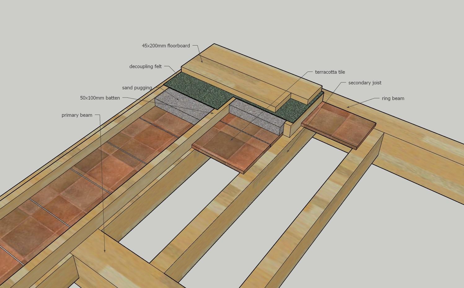
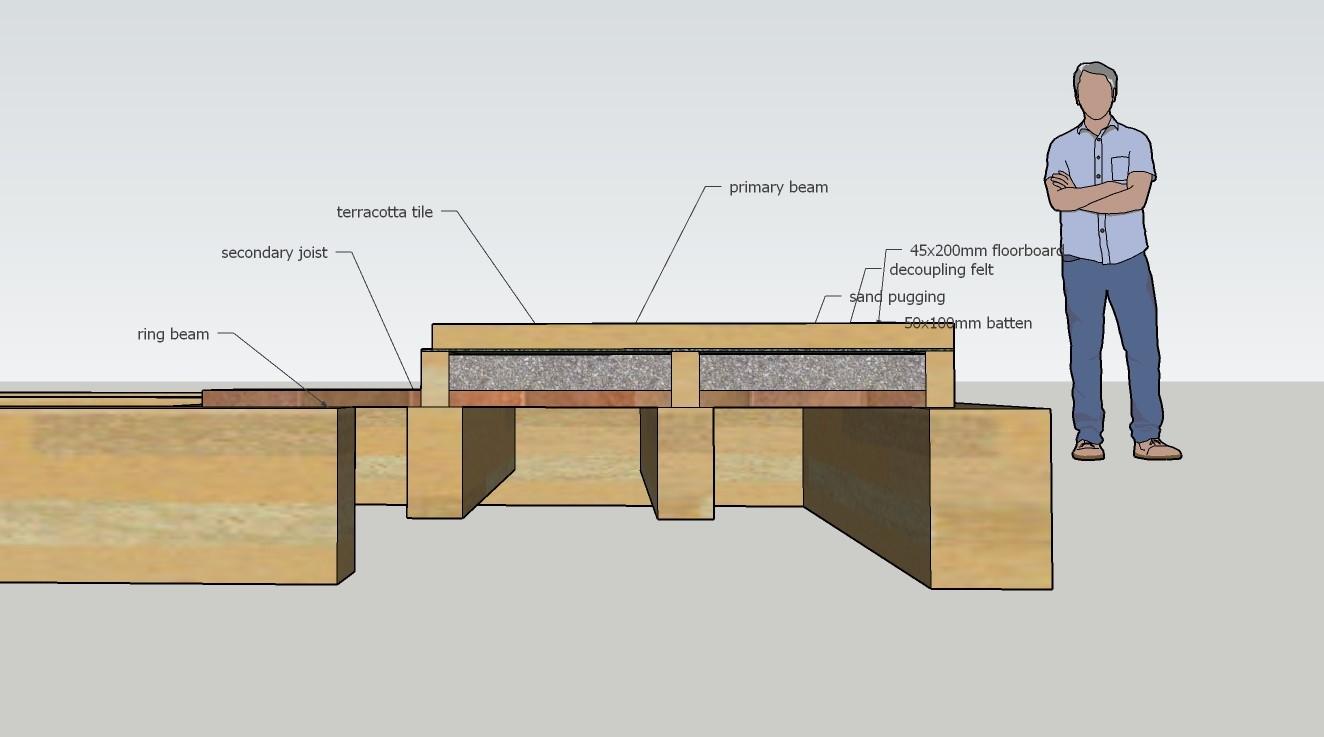
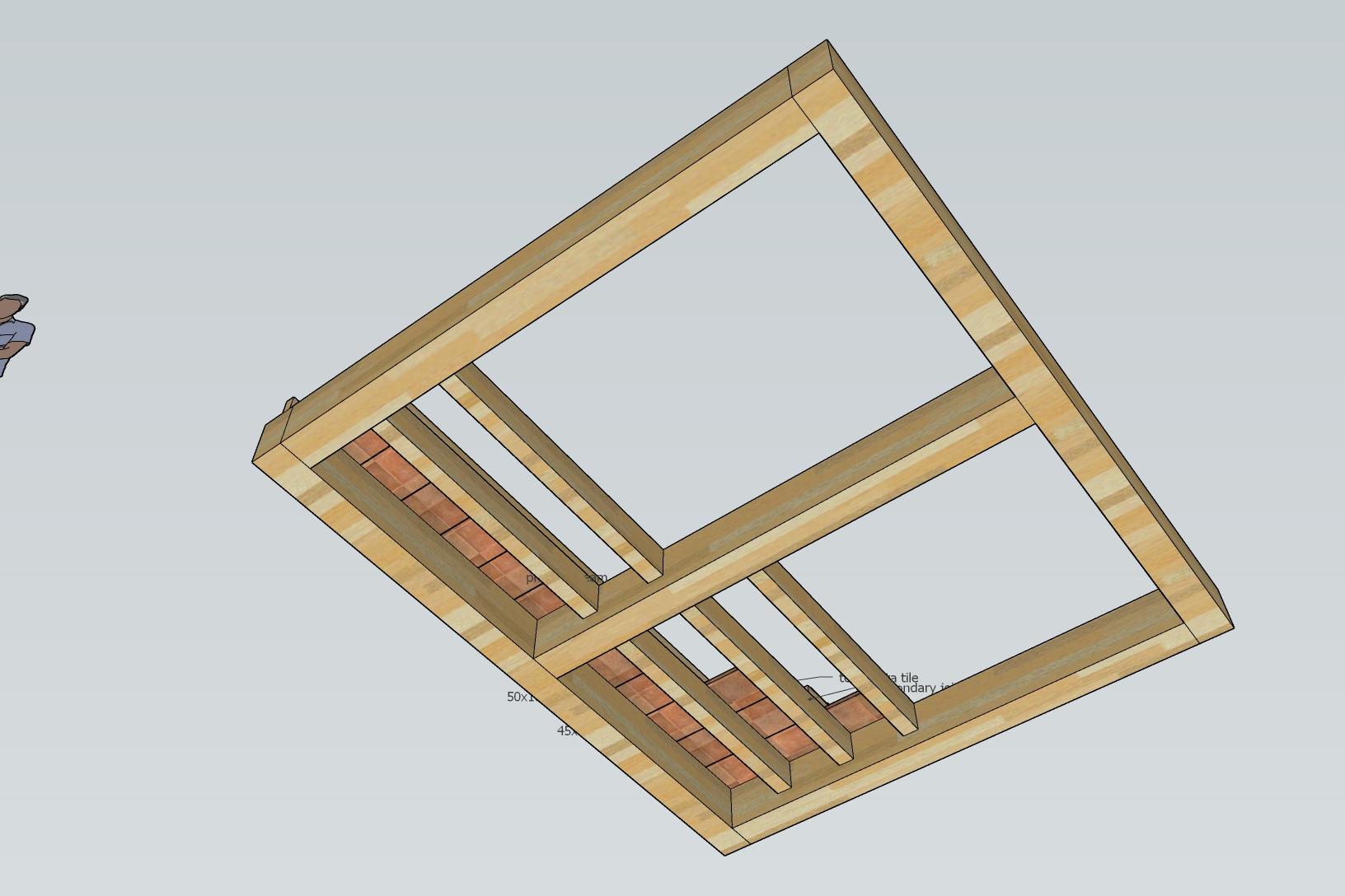
I'm trying to figure out an efficient (both environmentally and on the wallet, although I have a fair bit of tolerance for spending on the structure) structure for achieving a somewhat idiosyncratic combination of structural and aesthetic goals. I would like to achieve the following: The load-bearing structure of the floor is exposed to the room below as much as possible. The floor is reasonably stiff, without noticeable bounce or sag, and has load-bearing capacity significantly in excess of usual residential standards. The structure wastes as little space as practicable between the ceiling surface between the beams, and the floor surface above. Noise attenuation is decent but doesn't need to be amazing. UFH pipes can be accommodated, for heating/cooling both the floor and ceiling, with a low temperature delta. Room for other services is not needed, they will be accommodated elsewhere. All walls can be assumed to be load-bearing. The largest distance between them (in the short direction) can be assumed to be no more than around 4-5m, less in most cases. Sufficiently compliant with building regulations to avoid trouble. To meet these goals, I'm considering using heavy primary beams (e.g. 200x400mm glulam, oak, douglas fir, etc.) across the room in the short direction, with secondary thinner beams/joists (e.g. 100x250mm) connecting them orthogonally. For example, in a 5x3m room 2 or 3 primary beams could effectively divide the 5m span into three spans of 1.5m or four spans of 1.1m. The secondary beams would be dovetailed into the primary beams and ring beams at the edges of the room, so that the tops of both beams are level with each other; this can be achieved with a set of templates/jigs and a router. The beams would be thick and deep enough to provide adequate structural stability in the case of fire, and this excess thickness in unburned beams would contribute to stiffness. The beams should count as "narrow members" for building regulations, so fire-resistant coating shouldn't be needed. The secondary beams would be at a spacing of roughly 350mm of empty space between them (450mm centres with 100mm wide beams), and 400x300x30mm terracotta tiles laid across them. The tiles provide a finished ceiling surface with no further work required (convenient when ceiling height is in excess of 3m), and satisfy fire resistance requirements for the ceiling surface. Lime mortar or similar could be used between the tiles and to hold them in place. In the spaces between the tiles, 2x4" battens would be laid along the length of the secondary beams. The space between the battens would be filled with heavyweight pugging for both aiborne sound insulation and thermal mass, and UFH pipes can be laid within the pugging layer. A decoupling felt either above or below the battens & pugging layer provides impact sound insulation; if the felt is above the battens but extends down below the pugging between them, it also helps avoid pugging leaking from any cracks that might form in the ceiling. On top of the battens and across them, heavy floorboards (e.g 45x120-200mm, or even thicker if available for reasonable cost) act as both the structural subfloor and the finished surface. This should be significantly stiffer than the common solution of subfloor and thinner boards, due to the greater thickness of the layer and the optimal orientation of the wood fibers. T&G to constrain their movement relative to each other and to prevent gaps from opening between them, softwood for cost and being easier on the feet than hardwoods. Wear and patina on the surface is acceptable or even desirable. If carpets are used on parts of the floor, a thinner subfloor (e.g. plywood or non-visual 25-30mm boards) would be used on those areas to allow for carpet and underlay where applicable. All together, this structure would consume roughly 15cm between the ceiling surface (sans beams protruding below) and the floor, which compares very favourably with conventional constructions. An even thinner construction could be achieved by laying the floorboards straight on top of the beams, or even dovetailing them in between the beams, but that doesn't provide space for UFH and requires fire retardant treatment to satisfy building regs (or some other way to convince them to allow it), and could have issues with noise transmission. One thing I'm not entirely sure about is whether terracotta tiles would be strong enough to hold the pugging without risk of breaking. An alternative would be to reduce the spacing of the secondary beams, or to make the floor into a timber-concrete composite where the concrete is in compression and the timber beams below in tension. The latter would allow greater stiffness and/or shallower beams, but adds concrete, the shear connectors, and the complexity of engineering the structure. It is also not clear what would be the best solution for the floor surface in this case. Does this buildup look viable? Are there ways to simplify/improve it that I've missed, or alternative ways of achieving similar performace and aesthetic goals?


-
Juwo SmartWall is essentially identical to Porotherm and sold here; last time I checked the prices it was around £100/m2 for the blocks.
-
You would either plaster/render them on at least one side, or add a membrane.
-
Those blocks look like Porotherm T7 MW which has a lambda value of 0.07 W/mK. Over 365mm this creates a U value of 0.19 W/m2K. The reciprocal of this is a metric R-value of 5.21. Coverting this to US units with 1 K⋅m2/W = 5.56 BTU/(h⋅°F⋅ft2) gives 29. A metric U of 0.18 gives US R value of 31. If they have a lambda of 0.08 W/mK the metric U value would be 0.22, the metric R value 4.54, and the US R value 25.
-
Airtightness tape at windows / cavity closers
Lilly_Pines replied to Moonshine's topic in General Construction Issues
Make sure to cover the metal strips the window is mounted with in their entirety as well. I'd cover the entire closer with either tape or membrane even if you don't use membrane elsewhere. -
Continuous insulation applies to wood frame walls. From a quick look I think you'd need to use the R-values for mass walls: https://up.codes/viewer/new_york/irc-2018/chapter/11/re-energy-efficiency#N1102.1.2 The requirement is for an R-value of 8-21 depending on your climate zone and whether they consider the wall as having insulation on the inside. Obernburg looks to be zone 6 so R=21 would meet the requirements; Porotherm T7 365mm gives me a US R-value of around 31 with a quick and dirty calculation so you should be fine by the code. With the winters over there being as cold as they are I'd consider thicker blocks as an option if you aren't already committed to 365mm, but even 365mm seems to be 50% more than the minimum requirement. I'm a bit worried about whether your architect is the best choice for the project if they didn't know this (or didn't know how to look it up), and would take care to double-check everything else to make sure they didn't miss other important differences between clay block and stick frame construction. Disclaimer: I don't have actual experience but I've read a lot of https://www.buildingscience.com/ and know how to read technical text like building codes. I've researched clay blocks as one option for my house and I'm happy to answer questions with the aforementioned caveat that I mostly know things theoretically.
-
Window in timber weatherboard detail
Lilly_Pines replied to benben5555's topic in New House & Self Build Design
Here are some details with accompanying 3D illustrations: https://www.firstinarchitecture.co.uk/detail-post-timber-cladding-details/ The horizontal cladding detail includes external insulation but I don't think it would change that much without it; the finishing strip would just be less wide. -
I couldn't immediately find whether Zehnder MVHR units can balance the pressure of the house by supplying the make-up air for the extractor, but that's the first place I'd look. Theoretically all it'd take is running the supply fan a lot faster than the extract fan so it's just a question of controls and whether the MVHR has enough capacity for the extractor.
-
Recirculating is practically useless for particulates (example). Assuming the extractor catches all cooking fumes as they're produced, you need a HEPA-grade filter to properly remove the finer and most harmful pollution. If you aren't filtering almost everything away on the first pass they will make their way into the general breathing air and you'll be waiting for the recirculator to gradually whittle them down over time. I have never seen a consumer-grade recirculator with adequate filtration, only large and expensive commercial units. At that point it's probably easier and cheaper to get a real extractor and supply air setup.
-
The problem is two-pronged: too much artificial light in the evening and too little during the day. I've found that the right amount of light in the bedroom before sleep is more like 2 lm than the 200 lm commonly available from small LED bulbs. Given that humans (with normal eyesight) are perfectly capable of navigating outdoors at night in minimal moonlight, there isn't really a good reason to use significantly more light than that indoors either. If your lights have sufficiently gradual dimming that your eyes have time to adjust it's really nice for the house to be no brighter than the outdoors. As a rough heuristic I'd say that if you can see colours, it's too bright. Conversely, in daytime normal indoor light amounts of 200-1000 lux are equal to a very dark overcast day. I've found that the brightness of shadows on a sunny day (around 10,000-20,000 lux) is a good, comfortable amount but a bit expensive to replicate indoors so a more moderate amount of roughly 2,000-4,000 lux is a good goal for spaces people spend their mornings and early afternoons in. Everybody and their dog, building control included, will tell you that's too much light and they'll have various awful overilluminated offices etc. to support their argument but upon a closer inspection the claim falls apart. Those "overilluminated" spaces are almost always lit with uniform brightness and colour temperature with no dynamics or proper variety to the lighting, which practically never happens in nature; an awful overcast day on a flat featureless plain is probably the closest it gets, except that the "overilluminated" indoor spaces probably have the exact same brightness and colour at 11:00 and 17:00. In any real outdoor space humans inhabit there is at least the variation between shadowed areas that get less skylight and bright areas that get more, along with the diurnal cycle. When the sun is shining you also get the difference between yellowish sunlight and bluish skylight. If you replicate these conditions indoors by combining direct light at 4000-5000K and indirect light at 5600-6500K you'll likely find the effect of golden "sunlight" and bluish shadows very pleasant and almost no amount of light feels excessive as long as you ensure the right balance of brighter and darker spots and their positioning relative to yourself. (This is also likely to cure or at least significantly alleviate SAD, suffered by around 1/3 of the population in the UK.) Now if you have >2000 lux during the day, gradually tapering down to 0.2-2 lux at night, I'd bet the effects on your sleep would be dramatically lower than keeping the normal amount of lights on long past sunset. The relatively bright and blue light during the day should ensure wakefulness and the dimmer, redder evening light should set the contrast appropriately. Outdoor light is also usually too bright once it gets late, creating pools of illuminance surrounded by a stygian abyss. I like the idea of having a very small amount of light outside windows so that they aren't black panels of unknown but instead you can just about make out what's going on outdoors even with the (low amount of) lights on. Admittedly this gets more complex in public spaces that have to accommodate people with worse night vision at least until we get bionic eyes on the NHS or high-spec night vision gear at Specsavers for £30.
-
I normally prefer natural and hygroscopic insulation, but the combination of method and material here is really good for the application and looks solid from a building science perspective, at least to my (autodidact dilettante) eyes. Structure on the protected side, homogenous control layers all together, and so on. My main concern after ventilation (of both the house and the space under the floor) was VOCs and the foam seems to be pretty low on those as well, although I'd still prefer to keep the house empty and well-ventilated during and for some time after installation. If the floor is covered with impermeable material like vinyl tiles and water gets into the structure I could see it causing problems though, as drying is difficult in both directions.
-
Overhangs are modeled by variable shading; you'd increase the shading percentage in the summer months when the sun is higher so the overhang covers more. It's a bit fiddly and I'm guessing prone to errors but I'm not sure how this could be represented better. The g-value itself is just the g-value of the glass.
-
In the spirit of @Jeremy Harris's heat loss spreadsheet, I made a spreadsheet to estimate solar heat gain through windows. It's a bit more complicated topic than straightforward heat loss, but I tried to make it as easy as feasible. To use the spreadsheet, divide the windows and rooflights you want to calculate into groups, where windows in the same group face the same direction and have the same g-value. The groups can be named whatever you want; the names will be used as labels later in the sheet. For each group, input the direction the windows face (in degrees, north is 0, south is 180) and their slope (90 is vertical, 0 is horizontal). Sum the areas of all windows in each group. Once the window groups have been defined and the relevant values specified, the sheet will calculate the inputs you need to use in PVGIS. Windows facing between east and west are fully supported, and for these the inputs to PVGIS are exactly the same as used to specify the window groups, except that the direction (azimuth) is -90 at east, 0 at south, and 90 at west. For windows facing slightly northeast or northwest, the PVGIS values for windows facing east or west are used, and the spreadsheet calculates two different estimates of correction factors in an attempt to give an upper and lower bound for the heat gain. Windows facing significantly northeast or northwest should be ignored, as the error in the estimates will be too high for them to be useful. For rooflights only directions between 90-270 (east to west) are supported as I didn't feel like figuring out a correction method for them. For each window group, input the given azimuth and slope in PVGIS, and go to the "Monthly in-plane irradiation for fixed angle" in the result visualisation. For each month, input these values in the correct field. This is a bit tedious, but making the data collection automatic would be a lot more complex. You can add a shading value (as a percentage between 0-100) to refine the results if you want, but it is not required. The shading value can be defined monthly for each window group, to better account for factors like overhang, deciduous trees, or external blinds. Getting useful numbers is left as an exercise for the user, so just leave the fields empty if in doubt. Once all inputs are given, the spreadsheet calculates two different estimates of solar heat gains in each month. If there is a difference between the estimates, the high estimate is extremely likely to be an overestimate, and can be used to approximate an upper bound of cooling needs. The low estimate should be more accurate for winter heating needs, but should still be taken with a grain of salt. If the estimates agree, you don't need to worry about any of this. Credit to @Adam2 for the original idea of using PVGIS. Any errors and mistakes are mine. Feedback appreciated. Solar heat gain calculator.ods
-
I cleaned up the spreadsheet a bit so it should be viable for more general use now. The spreadsheet fully supports windows from east through south to west. For windows facing slightly northeast or northwest the sheet includes two different methods of estimating heat gain, attempting to establish a reasonable upper and lower bound. The estimates should be reasonable for windows facing close to east/west, but the errors will grow with more north-facing windows and individual judgement should be used on what windows to include. Instructions on how to get the radiation values from PVGIS, and the inputs to use, are also included. Credit to @Adam2 for the original idea of using PVGIS. Solar heat gain calculator.ods
-
I took monthly radiation numbers from PVGIS (slope 90 for windows or roof pitch for rooflights, azimuth wherever the window is pointing, I ignored north-facing windows but for slightly northwest/northeast-facing ones you could either use +-90 or make an attempt at correcting the window areas with the cosine of the angle difference) and used a customised version of Jeremy's spreadsheet: Sort your windows by which direction they face and sum their areas for each direction. For each direction, get the PVGIS data of kWh/m2 per month. Set the appropriate g-value for the windows (may be different depending on direction). To include shading, I set a monthly shading percentage for each direction to approximate overhangs, deciduous trees, etc.; this is the section where the most handwaving happens unless you have a good model of the house and its surroundings, in which case you probably wouldn't be using a rough spreadsheet to begin with. Multiply the PVGIS radiation by the area of the windows, the g-value, and subtract the shading percentage (multiply by (1 - (shading% / 100))), for each of the directions. This gives the monthly total solar gain, similar to how the spreadsheet has monthly heat energy inputs; the solar gain can then be subtracted from the heat inputs to see how much heat needs to be produced inside the house. I used a simple calculation of internal gains from occupancy, lighting, machinery etc. to get an approximation of the heating needed after solar and internal gains. This approximation won't be exact, but it seems good enough for questions like "will it reduce my heating need by 10%, 50% or 90%?".
-
I have, and purely economically it can’t compete, but unless I’ve gravely misunderstood something a borehole only requires a localised disturbance in the ground (plus whatever the drilling rig causes to the ground underneath it) while a horizontal loop requires a large open area which gets dug open and turned into something like a lawn.
-
The problem with running ventilation pipe in the ground is that 1. it requires a lot more groundworks than a vertical hole 2. you need to pay extra attention to drainage and lining materials because water will condense in the pipe and you don't want it to become a problem 3. large amounts of air require a large number of parallel pipes to reduce pressure loss which increases the ground disturbance. Using a liquid for the heat transfer is supposed to avoid these drawbacks, and at least in my impression is often suggested as an alternative when someone brings up ground tubes. Looking deeper into the matter, this paper gives some useful numbers on heat extraction rates, temperatures, etc. In 11c limestone, brine coming in at 1c and leaving at 3c can extract between 30-40W/m. Assuming that a halved temperature delta means halved heat extraction, that would be brine coming in at 16c, leaving at 15c, extracting 15-20W/m. For 3kW of cooling a borehole length of 150-200m would be indicated. Assuming thermal piles on the corners and middle of long sides of a 5x10m house the required length would be 25-35m per pile modulo differences in ground characteristics compared to limestone.
-
Building an enthalpy exchanger with high efficiency seems like one of those tasks that, while doable, are sufficiently annoying that I'm happy to leave it to people who do it as a job. Agreed on the shadow gaps, although they need to work with the aesthetic. The reason for the stupid amount of lighting is that I have seasonal affective disorder which means I get dysfunctionally depressed when in inadequate light. If I don't have my greehouse lamp (315W CMH, roughly 30k lumens) on it noticeably affects my mood even with the ~20k lumens remaining in the living room.
-
Assuming a house with 100m2 of area and 300m2 of conditioned volume, 600m3/h is 2 ACH. A human needs roughly 200m3/h of fresh air for a steady-state CO2 concentration of 100ppm above atmospheric levels. With atmospheric CO2 going up for the foreseeable future, this seems like a prudent precaution when 1000ppm has a noticeable impact on cognitive performance compared to 600ppm. 2 ACH in the example house is sufficient to achieve truly fresh air (which I'll define as a CO2 rise of 100ppm or less) for 3 people or a lesser standard of 200ppm rise for 6 people. The large exchange rate is also desirable for controlling dust when combined with filters at exhaust vents. Pipes are only required to connect the MVHR units (e.g. Brink Flair 300 Enthalpie x3) to the intake and exhaust, and to the air distribution system inside the house. If all internal structures are inside the conditioned and airtight envelope, and built of good materials that don't release nasty stuff, there is very little obstacle to using spaces within the house (like closets and other built-in furniture) to form parts of the ducting. This, in conjunction with commercial duct silencers, also avoids ventilation noise and crosstalk between rooms. A2A heat pumps still require air distribution inside the house and the most logical location inside the intake ducting of the ventilation system effectively just replaces the borehole with an ASHP outdoor unit as the source of cool fluid. Also, can you give me an example model of an A2A heat pump that gives 9-14 EER? Search engines are being really unhelpful here. Assuming a total pressure loss of 100Pa (a bit challenging, but achievable with low flow rates compared to duct sizes) the ideal power consumption of 600 m3/h would be 17W. Using two EBM Papst R3G220-RD53-03 fans in series (intake & exhaust, each seeing 50Pa) I'm seeing roughly 50W combined and a sound power level of 57dB(A) each. According to its PHI certificate Brink Flair 300 Enthalpie has a specific electric power of 0.21Wh/m3 at roughly the same operating parameters, resulting in 120W consumption which is not too terrible. Operating it without its built-in filters and using significantly larger and less restrictive (e.g. 605x605mm) filters should help a bit. If I use the fan-only numbers, and give the brine pump another 50W to be conservative, that's 100W steady-state, for a cooling power of maybe 3kW at 30c->15c or a CoP of 30 for the intake air (MVHR would only get the intake temperature down to something like 22 and further active cooling of the air indoors would be necessary). On further thoughts increasing the ventilation rate to cool the house down is nonsensical so additional cooling beyond that should be distributed from hydronic pipes in the structure (ceilings are the best place for them, as they have the least obstructions; I'm planning an open grid of exposed beams and joists with e.g. terracotta tiles between them, so anything that needs fastening to the ceiling has an obvious and visible structure to attach to so the pipes wouldn't be in any danger).
-
Insofar as the diurnal buffering goes, the thermal mass* required seems achievable. If we want to buffer 50kWh/day at a temperature change of no more than 5K, and the house might have 500m2 of exposed surface area of floors, walls, ceilings etc., it's 100Wh/m2 requiring a usable heat capacity of 20Wh/m2K or 72kJ/m2K. Most building materials are more or less 1kJ/kgK meaning that a useful thermal mass of 72kg/m2 would suffice. Some materials like wood are better but their low heat conductivity means only the surface participates, some, like granite, are worse but their high density and conductivity make it less of an issue. Looking at clay plaster in particular, its higher heat capacity of 1.3kJ/kgK means only 55kg/m2 is needed, and at a density of 1.6kg/dm3 this means 35mm layers on exposed walls. A similar calculation for floor and ceiling materials shows that many materials commonly used for thermal mass would provide adequate heat capacity. Another option to help with the cooling would be to circulate the cool water through the floors, walls and ceilings like reverse UFH. This has the additional benefit of not requiring forced air movement beyond what is necessary for fresh air, and low-temperature surfaces make high-temperature air significantly easier to cope with. With a bit more complexity the same pipes could be used for low-temperature heating in the winter (e.g. 23c) to improve radiant comfort without wasting heat on air that will soon be exhausted anyway. * Yes, "thermal mass" or perhaps "exposed/usable heat capacity"; decrement delay doesn't apply when practically all of the heat is coming through the windows.