Adsibob
-
Posts
3604 -
Joined
-
Last visited
-
Days Won
10
Everything posted by Adsibob
-

1st idea from architects - feedback welcomed!
Adsibob replied to Beechgate's topic in New House & Self Build Design
Agree. If executed well, this is your wow factor. -
1st idea from architects - feedback welcomed!
Adsibob replied to Beechgate's topic in New House & Self Build Design
I agree with all of this. Just wanted to add that we have a green roof with lots of beautiful succulents and some flowers, but it is on a pitched roof. Do you don’t have to have a flat roof to get that aesthetic. Very achievable on a pitched roof too. -
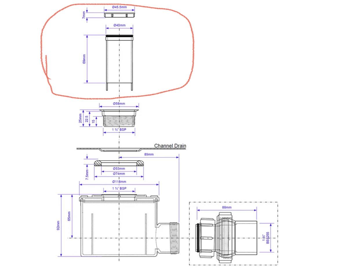
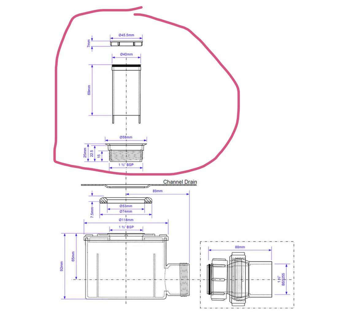
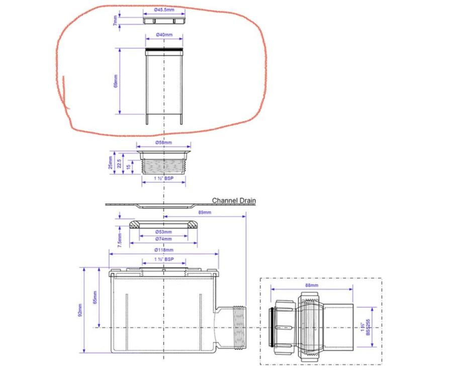
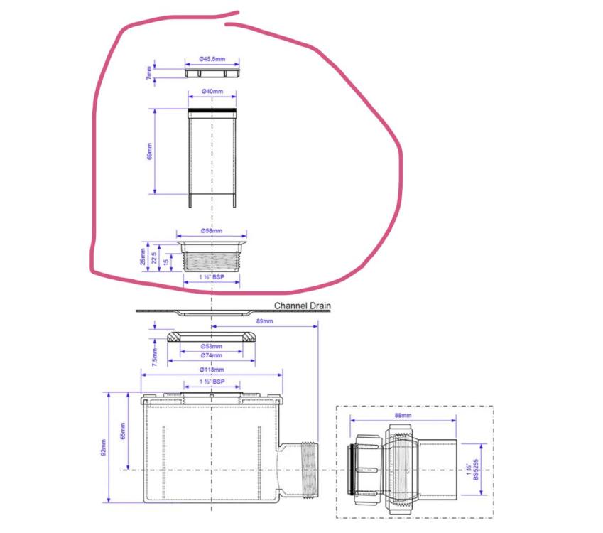
Yes, the water was completely confined to the wet room area. Ironically, as I was showering, I was thinking so nice not to flood the wet room for a change (because of the slow draining waste, we were occasionally flooding the wet room - but I can’t see how that caused the leak, as it’s a wet room and leak only started after I fiddle around with the fishing tool). To clarify, only thing I removed (and then re-instsated) are the two circled items in the photo below:
-
Nope. Only thing I did was prise off the top item of the two circled below, fish around for 15min, remove hair, then realised I could pull out the second item circled below, so pulled that out too (it came out really easily with no resistance, which made refocusing hair much easier. Then I returned everything, to how I thought it was. But apparently not. Any ideas?
-
I sometimes wonder if my DIY efforts are cursed. First shower after I successfully unblocked the drain: SWMBO sticks her head around the bathroom door and says “turn it off, it’s leaking into the utility room”. I thought I had been gentle with my fishing, and looking back at the diagram posted above, I cannot see what damage I couldd have done. But unless this is a massive coincidence, the laws of temporal logic suggest my unblocking has indeed caused the leak.
-
@saveasteading I did not intend to criticise the SE. I was actually being critical of the way the SE was instructed, ie not via an architect and not with a detailed brief. At least one of those two things was required here. This of course assumes the architect would have given a detailed brief in accordance with the OP’s wishes. If no special instructions are given, then the SE’s remit is limited to designing a beam that works and proving to the BCO that it will work if asked by the BCO for calculations (my BCO asked to see all the SE’s calculations, not just the drawings). I guess I was lucky, in that my architect specifically asked our SE to conceal some of the beams in our construction, which would have really ruined aspects of the project otherwise. My architect also ensured the SE knew how much clearance we needed under the beam for our extension, and also asked for a certain maximum deflection. These were things I hadn’t really thought to ask, and had I not had my architect liaising with the SE, we would have ended up with a much worse end product. My architect and SE has worked together on previous projects, so I think that helped.
-
Brass hydrosure hose end connector not working
Adsibob replied to Adsibob's topic in General Plumbing
So after some testing, I’ve worked out that it must have a one way valve in it. Bizarre, because every Gardena and Hozelock connector I’ve used has always been two-way. Other disappointment is zero instructions provided by WaterIrrigation.co.uk for their “HydroSure Heavy Duty Garden Impulse Sprinkler on Spike”. Currently sprinkling in a 330 degree arc when all I want is 180. Also not clear it’s actually fit for purpose ad seems too water the grass far away from the sprinkler, and right by the sprinkler, but not in the area between. I guess I will find some instructions online, but not even a note with their packaging that directs you to their website for instructions. -
Brass hydrosure hose end connector not working
Adsibob replied to Adsibob's topic in General Plumbing
Well I bought the Geka tap splitter, which as you can see from the above link, has an integrated male connector at each outlet. The brass hose end connector is by a different manufacturer, Hydrosure, but it was all bought from the same supplier Waterirrigation.co.uk, so I assumed all their products have universal connections. The “click” sounds solid, but maybe there is an incompatibility. If one uses this Geka tap splitter, which female ended hose connector are you meant to use with it? -
Brass hydrosure hose end connector not working
Adsibob replied to Adsibob's topic in General Plumbing
My plastic connector broke, so I thought I would upgrade to brass, as not that much difference in price. But so far a complete fail. -
Brass hydrosure hose end connector not working
Adsibob replied to Adsibob's topic in General Plumbing
The tap is switched on, yes I do have a brain. I have a tap splitter like this https://www.waterirrigation.co.uk/geka-plus-four-way-tap-connector.html?gclid=CjwKCAjw1MajBhAcEiwAagW9MVC-yPIHsf03s4CQwx8aH9zt5jco6lFwAiYRqDqFrkZ4nqz3SphUxBoCHAkQAvD_BwE screwed to the tap. I have three of the outlets closed, and the fourth is open. It is to the open one which I’ve connected the hose end connector. With it disconnected, plenty of water comes out the male end of this fourth outlet of the tap spitter. The brass hose end connector’s female connection clicks into place nicely when coupled with the male connector of the hose splitter. But no water comes through. I’m wondering if this brass hose end connector with Waterstop has a one way valve fitted to it, and is designed to only work at the other end of the hose? -
I bought various components to make an irrigation system, including this brass hose end connector with Waterstop: https://www.waterirrigation.co.uk/hydrosure-brass-hose-end-connector-with-waterstop-13mm-1-2.html The way this should work is that when it is connected, water can pass through it, but when it’s not, water doesn’tpass through. Well I can’t get any water through it. Shaking it about whilst disconnected to anything, I can feel the valve open and close, so it’s not jammed. Don’t understand why it’s not working. Also surprised by how small the holes are to let water through. Anyone have experience of this? What am I doing wrong? Seems crazy it just doesn’t work out the box.
-
I think this is an oversight. An SE is only expert in structural engineering. He has no appreciation of aesthetics, convenience or even client management. This is why they are traditionally employed by, or in conjunction with, an architect. There are of course exceptions to this general rule, but in the same way you wouldn’t ask your kitchen fitter to design your kitchen, or your tiler to give you tips on interior design, you don’t leave key dimensions that impact the design of your extension to an engineer.
-
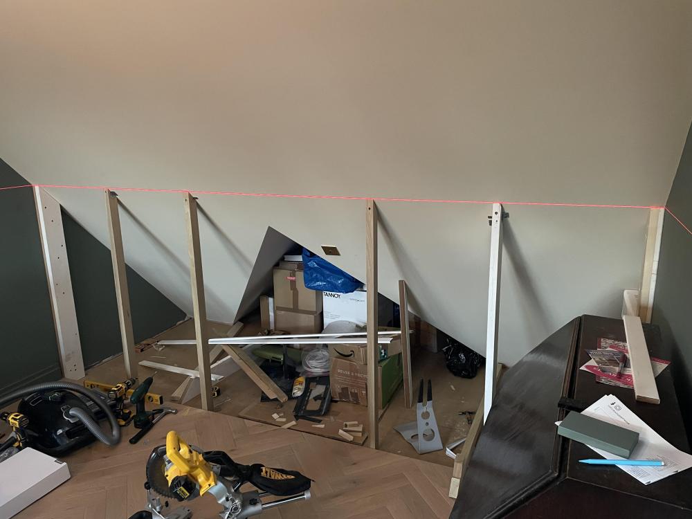
i thought about that, but I would have needed to cut a 3.3m length of timber diagonally, and at the time I didn’t know mitre saws existed. I thought about buying an arris rail but even then the angle wouldn’t have been exact. I think it’s strong enough. All but one of the uprights are made of tulipwood, 38mm by 58mm. The one exception is MDF bound in a resin primer, which is 32mm by 125mm. Each upright is fixed at six points: three metal brackets at the bottom end; and two metal brackets and a screw that goes through the tulipwood and then into the ceiling at the top end. They aren’t carrying much weight as it’s just 18mm MDF doors. I’m sure there are better ways of doing this, but I’m just a novice DIYer, impressed that I managed to get everything pretty straight! I did ask my builder to do this (when I learned, to my surprise, that it wasn’t included in the original contract) but he wanted money I didn’t have. So I’m leaning as I go. Do others really think it’s not strong enough? if so, should be quite straightforward to add battening in between the uprights to strengthen the frame; I’m just not sure it’s necessary.
-
That’s an interesting thought, I will check with the door supplier.
-
So I need to order my doors. I will hang six doors, one from each of the six posts in the photo above, and I want them to go floor to ceiling. The height from the FFL to the laser line (also in photo) is exactly 1266mm for all posts except for the ones attached to the walls. The left hand wall post is 1264mm and the right hand wall post is 1270mm. There will be a 4mm gap between doors (the posts will therefore be visible, but they will be painted same colour as the doors). Will a consistent door height of 1256 work? I have taken the lowest post height of 1264 and then subtracted 8mm to allow clearance for the doors to open. But I’m wondering if this will give me clean horizontal lines top and bottom? Other option is to go for 1258 which is 1266 (ie the height of 4 out of the six posts) subtract 8mm and accept that the left most door will only have 6mm of clearance between it and the floor and the right hand post will be a bit more visible. doors are going to be 18mm thick MDF, and a bevelled 45 degree back edge along the top to fit nicely under the sloping ceiling (although this is closer to 47 degree slope).
-
I know how a typical sink and toilet trap work. But this appears different, though I guess it’s the same principle. And looking back at the drawing of the waste system which I posted earlier in the thread, it all makes sense now.
-
Finally got around to unblocking this, having received the bendy plastic fishing tool with jagged edges from Mr Bezos a few weeks ago. Without doubt the most revolting maintenance job I’ve done so far. Fished out handfuls and handfuls of SWMBO’s hair out of the drain. It was actually quite a sophisticated drainage system. What I thought was going to be a long 40mm pipe, was actually only about 9cm long before it hit what was effectively a bowl. All the hair was stuck in this tube. The tube could be pulled out altogether (wish I’d discovered this at the beginning of the task, rather than at the end). So I think the way it works is water fills the bowl, and only once the bowl is overflowing does it drain to the actual waste pipe. The advantage of this system is that any blockage should mostly stay very local. Though it did make me wonder whether there is a permanent cesspit of stagnant water (fermenting SWMBO’s shed hair) within that bowl.
-
You can also see the DeWalt mitre saw on the floor. This was lent to me by the same family member who supplied the laser level. The main posts are now all in, I just need to order the spray painted MDF doors and fit them. I May also put some additional posts in towards the back of the attic nook so that one or two of the cupboards can have shelves in them.
-
Yep. My relative bought me a laser level. Made the job so much easier:
-
Ah yes, sorry i didn’t read the OP properly. I would just go with the 6mm ply then.
-
The calculator cited was this one I think, but it is designed for shelves: https://woodbin.com/calcs/sagulator/ but I guess if you have support from above every 400mm, it’s perhaps similar in principle to a 400mm depth shelf. Either way, I think 6mm would just about be okay, as long as you added additional bracing for any pendants. But why are you using plywood as your ceiling? You can’t plaster plywood.
-
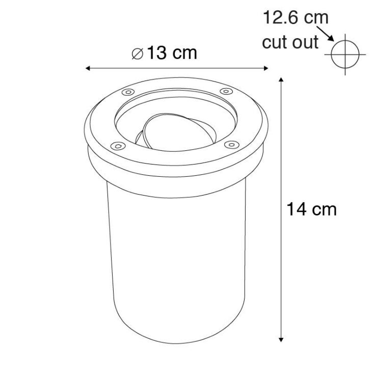
I need to change my driveway lighting. Currently we have Phillips Hue GU10s in some wall lights, which are surface mounted onto the wall. It works well. Some of those wall lights will need to go however, and only in ground spots (uplighting the wall) or in wall spots will work. In either scenario, the fitting will effectively be incased in concrete. The fitting looks something like this: Will the concrete wall/floor all around it interfere too much with the signal, such that I won't be able to control it with the Hue app? There will be other Hue lights in the driveway that won't be encased in concrete, so they will create a fairly decent mesh, but probably nothing within 3m or so of the ones encased in concrete.
-
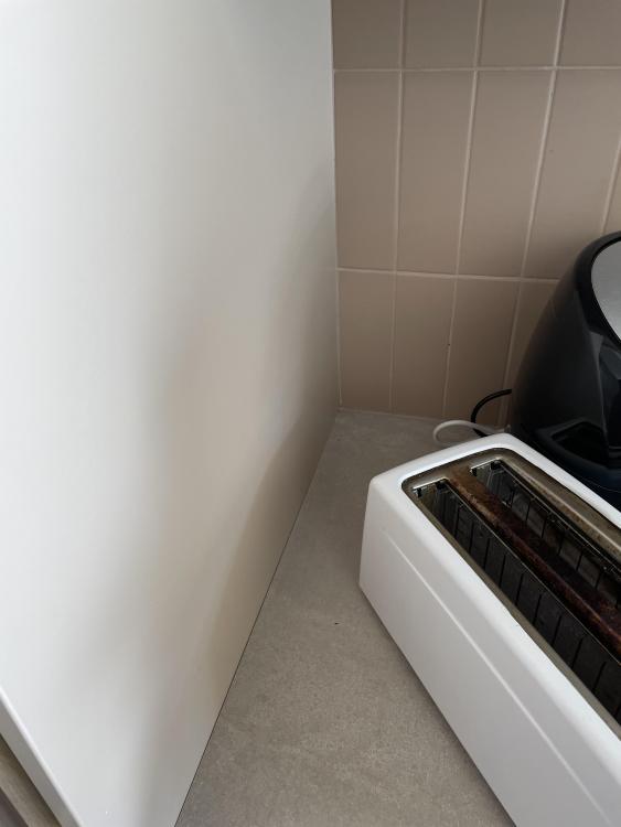
A year after our main build finished, the builders are due back next week to do snagging. In this photo of our kitchen, there are two joins between the carcass end panel on the left and: 1) the back splash tiles - which has been jointed/filled with regular tile grout 2) the worktop, which hasn’t been jointed/filled at all - there is a small gap, about 0.5mm to 1mm thick. The grout join on number 1 has started to crack. Suggestions for filling number 2. Should I get them to redo number 1 with something else? What?
-
InitiallyI was starting with a 45 degree dud, and then shaving that to see if I could get it to work. This was far to iterative, so I abandoned that method in favour of using trigonometry to “design” the right angle, from then on, I pretty much got all of them correct except for two where I forgot that a line I was working from wasn’t actually perpendicular to the wall. The floor plan definitely shows a perfect rectangle, but my builder didn’t build three room that way.
-
Right, I’ve googled a mitre saw. Can’t believe such a thing exists. If it can cut a 47 degree angle, it would have saved me quite a bit of time.