JulianB
-
Posts
85 -
Joined
-
Last visited
Everything posted by JulianB
-
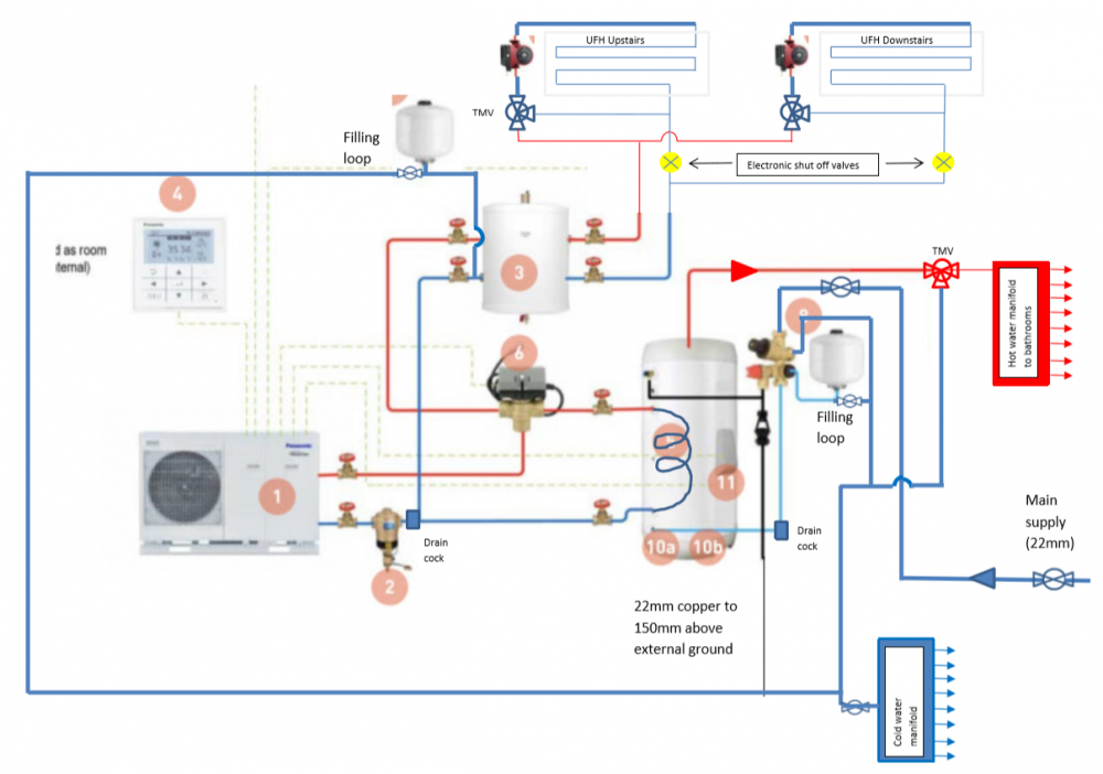
Thanks for that! I shall have a good read through! Good point re. only one filling point (DOH!). I have removed the one onUFHv4.pdf the DHW expansion vessel as presumably this fills from the main supply feeding into the PRV. Hopefully I'm just about there now!
-
Oh dear, hopefully all is alright on his end? I'm not sure how I feel about integrating a Raspberry Pi into the system - part of me would like to keep things as simple as possible and whilst I haven't had first hand experience with Pi's, I do wonder if you might get the occasional niggling issue? My initial thoughts were to somehow intercept the call for heating from the HP / thermosat, and drive two relays which would in turn be connected to a secondary power supply to the UFH pump and the electornic shut valve. When there is no call for heating, the two relays will be NC, i.e. shut valve closed, together with a 'complete' secondary supply to the UFH circulation pump, which would be on a simple timer to ultimately dicatate when it receives supply. When there is a call for heating, both relays would open, and normal system operation would resume (regardless of the state of the secondary supply timer). What I haven't investigated is the feasability in terms of finding a suitable 'call for heat' signal which would drive the relays, and whether running the secondary power supply to the UFH pumps would cause any adverse affects through it's primary wiring system. Thoughts?
-
Thanks; A filling loop near the filter (item 2) on my diagram, prior to my drain cock? Is this filling loop over and above the 2 on the expansion vessels? Also could I ask what UVC you went for? Good point, thanks! I recall reading Jeremy's blog re. the noise transmission without the flexible pipework sections; Will have to make it a point to rememder this one! Whilst on the subject of Jeremy's blog, I can't seem to access it anymore, has it gone offline? With regards to the electronic shut off valves when running the pumps solely to even out slab temp, could I ask what logic / controllers people are using. I can see the basic principle of shutting off the return leg to force the UFH pump to draw from the return legs of the UFH manifold, however I presume this 'mode' / state of control needs to be aware of when there is a call for heat in order to reopen the return leg? Also would there be benefit in positioning the electronic shut valve further upstream on the return leg from the buffer to HP in order to circulate a greater volume of fluid? I could see this being a potential benefit when trying to kerb solar gain which might become an issue, however am not sure if a single electronic shut valve would create any conflict between the two UFH manifolds?
-
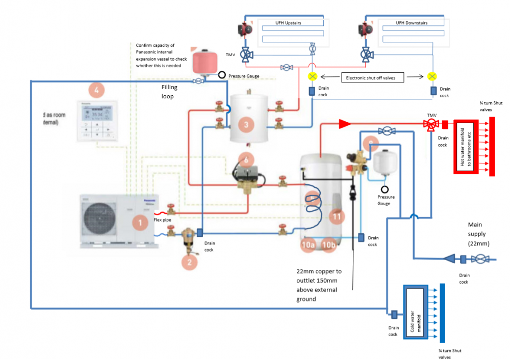
That is a good point. My UFH volume is ~97L, plus the 50L buffer...haven't found anything online to confirm the size of the internal expansion vessel. Will ask the supplier on Monday...fingers crossed Thanks!
-
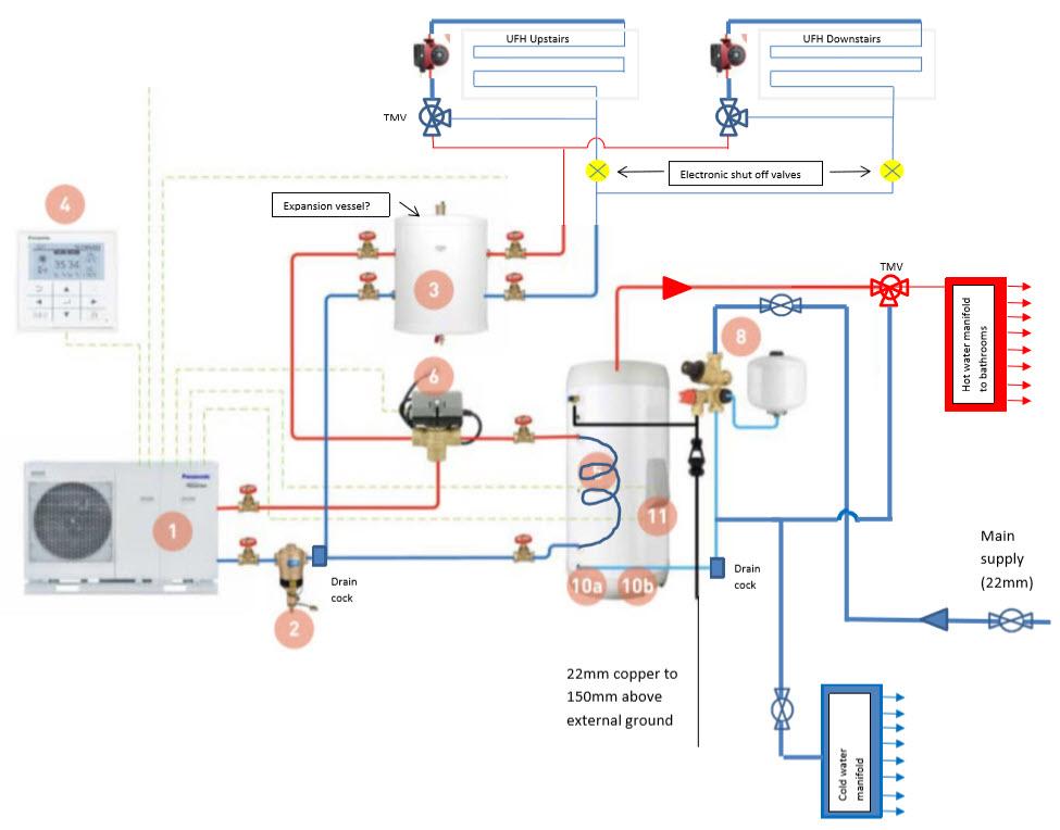
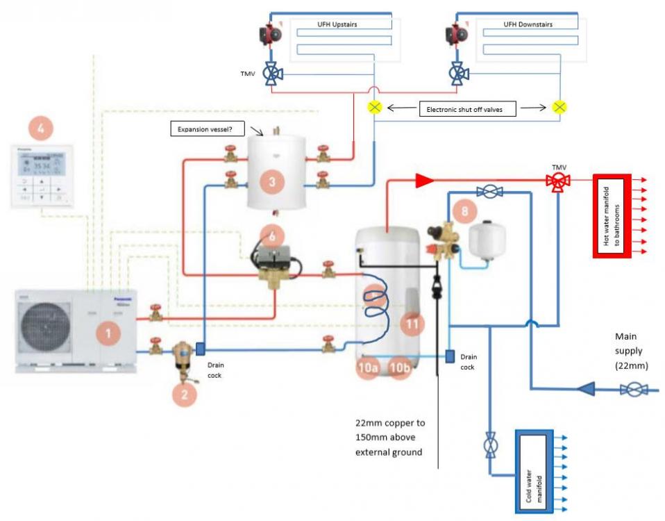
Thanks for that Pete! Do you have any photos of the install by any chance? Did you go 28mm copper from the HP or plastic pipe, and did you opt for glycol or water + inhibitor seeing as you had quite a volume of fluid in the buffer tank + UFH? Thanks for pointing that out! Hopefully the revised schematic below should now look a bit better...I've put the filling loop on both expansion vessels and connected the heating system expansion vessel on the return side as I figured it would be more efficient connecting to the lower temperature side...thoughts? Would there be anything else that I'm missing...how about drain points and shut valves, am I lacking any trivial ones? I'm trying to keep it as 'lite' and simple as possible...I've seen some schematics with double check valves, are these really needed? UFHv3.pdf
-
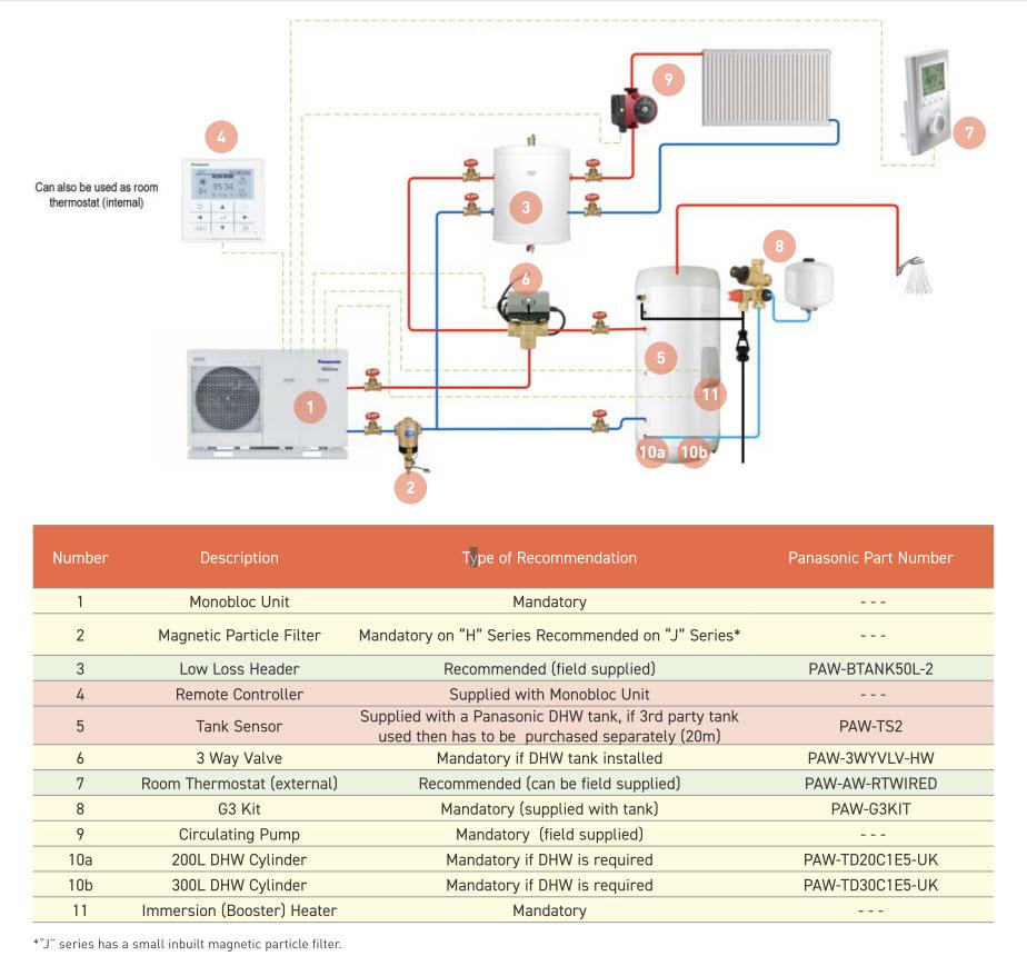
Evening all, Was in two minds whether to hijack another thread on the subject, but in the end I thought it may be better to post a fresh. As with many others, I'm honing in on my plumbing schematic, the bulk of which I hope to be completing myself (with the exception of the G3 sign off). I'm in the process of purchasing a Panansoic TCAP ASHP, which comes with a circulation pump, expansion vessel, strainer and flow setters in built in the monoblock unit. I was initially tempted to go down the route of a pre-plumbed cylinder, however due to me not having a great deal of space and hoping to fit it all under the stairs, opted for greater flexibility with individual components. The runs from UVC to both ASHP and bathrooms is under 5 metres (the house is pretty compact!), and sit on the ground floor as the house is 'upside down'. We expect quite a bit of solar gain with two glazed gable ends (1st floor), and hence are going down the 'JHarris' route of pumping the UFH to even out the house for the majority of the time (do people run these 24/7?). I've adapted what started off as the schematic on the Panasonic installation manual. It is far from pretty, apologies in advance! Panasonic advise on a 50L buffer tank however don't really mention whether this should be direct or indirect. I presume if this is indirect, an additional expansion vessel would be needed? Also, would the general recommendation be for the UFH side to be connected to the coil end of the buffer tank? I haven't placed a ASHP by pass, but have read these are recommended and should be as far away from the HP ? Also I've noted that the 3 way valve might not be the most popular choice! Any comments / advice would be greatly appreciated Thanks! UFHV2.pdf
-
CheckList for ASHP self installation
JulianB replied to swisscheese's topic in Air Source Heat Pumps (ASHP)
Apologies! Schematic below (hopefully)
-
CheckList for ASHP self installation
JulianB replied to swisscheese's topic in Air Source Heat Pumps (ASHP)
Good to hear! Out of curiousity could I ask what sort of issues you came across with the LG... How are you finding the Panasonic? The 9kW version is the same one we are most likely going with. I don't suppose you'd have any pictures of the install by any chance? I intend on following the schematic below...All that data at your finger tips must be tantalising! How was it been performing so far? -
CheckList for ASHP self installation
JulianB replied to swisscheese's topic in Air Source Heat Pumps (ASHP)
Morning All, Re-starting this thread as contemplating going down the DIY install route for my ASHP. The current plans are to go with a Panasonic TCAP with a 50lt buffer tank as per their recommendation (sounds straight forward!). I understand that the G3 kit would need to be signed off annually by a suitably qualified plumber, and I'd need to do my research with regards to regulations around routing and what not, but were there any significant pitfalls in regards to the actual ASHP setup and commissioning. I've gone through the installation manual and can see the numerous options for setting up the control system, but other than that it does appear quite simple? My feed/return from the ASHP will be a short 2m 'above ground' route, which simply runs through an external wall which already has a duct in anticipation, and under the staircase where I'm hoping to site the UVC / buffer tank. I have thought about their DUO pre-plumbed tank which offers a 300l +70l buffer tank in one package, but not sure if this will fit under in the allocated area, and whether this will work out any more cost affect or quicker in the long run. The supplier of the ASHP is trying to steer me down getting an installer to do it, which I can understand seeing as he'd have greater piece of mind w.r.t. the warranty Has anyone had any good / bad experiences in going down the DIY route please? -
Morning All, Thought I'd resurrection this discussion as I'm about to embark on the installation of our sewage treatment plant. We've opted for a 7 person GRAF one2clean and the supplier has recommended to backfill with pea shingle. The ground is heavy clay, so it is quite difficult to really establish where the water table is as any rainfall tends to just collect and sit in any hole we've dug. The tank will most likely sit a maximum depth of 1.5-2metres below current ground level, and land continues to fall away beyond our back garden. In the fear of the thing shooting out of the ground weeks after I've broken my back installing it, would the general consensus be to fully submerge the tank in concrete? Is the pea shingle route too risky?
-
Pipe spec for field ditch discharge
JulianB replied to JulianB's topic in Rainwater, Guttering & SuDS
What did you end up doing may I ask? On a side note, with regards to silt build up in flexible pipes...just a random thought but could there be a likely scenario where the silt fills each trough in the pipe and hence it begins to perform as a 'semi smooth' internal bore? The issue we have with any form of tank or soakaway on our site is that we are very close to the perched water table (despite being on a hill, around 15metres above the canal), which we learnt when digging the last soakaway hole...would a stormwater attentuation tank rely on an electric pump to empty, as if this is not the case and it relied on gravity / a lower outlet, I would imagine that it would be filled up by the surrounding water table pretty quickly. -
Pipe spec for field ditch discharge
JulianB replied to JulianB's topic in Rainwater, Guttering & SuDS
Thanks for the replies. We had spoken to our BCO about it as we had originally gone for an oversized soak away however at the depth that we ended up at, the percolation test numbers weren't representative and we found that we were wasting our time. I had read up on needing premission from the EA and had contacted them etc, however given that the cottage has an existing septic tank and soakaway to an unknown location, the BCO seemed happy enough to let us get on with the laying of the pipe without speaking to the EA? I've currently got two flexible pipes down, but it sounds like I will need to retrench once the weather gets a bit better to lay another 110mm rigid pipe, presumably in shingle? I've seen that they do a twin walled land drain which has a smooth interal bore - not sure if this would be better suited or less likely to get crushed or potentially remove the need for the shingle as I'd need quite a bit to get us the 40m trench length! Regarding the flexible (perforated) pipe around the property, I've read mixed arguments on here in regards to wrapping it in non woven geotexile membrane when in heavy clay areas; some suggest it actually increases the rate at which it will eventually clog up...thoughts? -
Evening All, I'm in the process of my extension project, and given the recent heavy rainfall and subsequent flooding (on site...heavy clay ground), have turned my attention to the storm water drainage. Whilst nothing is connected at present (hence the site flooding which is up to ground floor beam and block level), we have planned for two 100mm flexible land drain pipes to run from our cottage, across the adjacent field and into a nearby ditch (40 odd metres away). One pipe will service the sewage treatment plant, whilst the other will be used for storm water. The question is, given that we are unlikely to connect the pipes this winter, in time for a preview of their performance in these sorts of conditions, would this solution likely be adequate, as I'd prefer to not find out after having decorated and moved back in! Any thoughts are much appreciated! Julian
-
Yeah I see your point re. opting for fibre insulation - my only concern is whether over time the fibre will compress / sag and you end up with an air gap to the underside of the floor. PIR gives you a little more structural rigidity? Thanks; will definitely keep that in mind! Floor joist depth is 220mm; not sure if our first floor would support beam and block seeing as our inner leaf is constructed out of the 2.9N blocks? Good luck! I came across a few examples of people threading them through the webs - are you concerned at all about the length of pipe that will be submerged in your floor and not in contact with the underside of the floor?
-
Thanks for the advice, sounds like a good route to go down (drum roll!). How long did it take you to get through that job?? I wasn't aware of the need to glue the boards to the joists, thanks for that! Re. spreader plates, I wasn't too keen on them as I couldn't imagine insulating the underside with PIR without leaving considerable gaps given their profile (unless I were to use some sort of spray foam?). The routed board option does give you a nice smooth surface to work with on the underside
-
Morning All, I'm aware that this topic has been covered quite abit over the years (sorry!), however I've still got a few unanswered questions for my particular application... We're in the process of building an upside down extension (i.e. living space upstairs), and are planning to install UFH throughout (through ASHP). All the heat loss calcs check out. With respect to the first floor build up, we were initially going down the 'Torfloor' or similar option i.e. a routed structural board, which we would then cover over with engineered wood flooring. PIR insulation would be installed on the underside between each Easi Joist. This decision was primarily driven by not having a generous amount of head height at first floor level (just shy of 2m at the perimeter, with a vaulted 45 degree ceiling). We are now expecting delays on the oak roof trusses and hence the first floor is likely to be exposed to the elements for a longer period of time than expected, at the wrong time of the year... Seeing as most routed chip boards are not weather resistant in the slightest, our options are either to temporarily board the floor (spare ply boards etc) together with DPC to (hopefully) protect the joists, OR go down the route of using a weather resistant 'plain' permanent floor board at this stage, and later on down the line install a routed (non structural) insulation board to lay the UFH pipes, ultimately raising the FFL by ~20mm. The upside of the latter option would be that we could potentially get cracking with the floor now (and only do it once), giving us a solid platform to work off as we continue to build up walls and eventually install roof trusses and what not. The natural negative is the floor height, however I've wondering whether the fact that the UFH is now encased in insulation rather than for example the TorFloor chipboard, would actually make it perform better as it is not directly in contact with the floor joists. My final query is 'just how important is insulation between first floor joists' when the floor is technically within the thermal envelope of the building. Would there be a valid argument that the whole floor would become a heat sink and continue to function fairly efficiently, or would the losses to the perimeter wall within the floor joist depth be far too great to make any sense? Any comments / advice would be much appreciated!
-
Lintel advice for below ground level
JulianB replied to JulianB's topic in House Extensions & Conservatories
Thanks for that, now it makes a lot more sense! Unfortunately I'm exiting the underfloor space perpendicular to the beam direction and hence the blocks would be spanning the final section and resting on the inner leaf. I think if I had a block bigger than 440, then I could happily span across the underground drainage opening in the inner leaf, not sure what other options I've got... I'm hoping that if it is very close I could get away with the rest bend protruding through the beam and block floor seeing as we've then got the insulation and screed, and live with the bigger opening in the block... which would then be covered by the insulation and screeded over? -
Lintel advice for below ground level
JulianB replied to JulianB's topic in House Extensions & Conservatories
Hmmm I don't think I quite understand this approach. Are you saying to use a pipe wrapped in insulation as a form to cast some concrete which would then carry the weight of the block floor? The problem with that approach is I would no longer be level for the last block coming off the beam, to the perimeter of the inner leaf if that makes sense -
Afternoon All, We've finally managed to lay the foundations after having excavated the best part of 500 tons to clear site together with the challenging underpinning and retaining walls. We're now onto the build to the underside of the beam and block floor / DPC and things are looking pretty tight in terms of underground drainage. Due to us not having a great deal of space under the floor (150mm), we do not have the luxury of installing a concrete lintel above the openings for the soil pipes. As a result I've been thinking if a galvanised single leaf angled lintel would do the job or if this is a 'no no' being under external ground level, however not in direct contact.Not really sure what other low profile lintels are out there, and the exits are perpendicular to the direction of the beams and hence would require the flooring blockwork and slip bricks to rest on these sections. Would anyone have any suggestions? Thanks! Julian
-
Come to think of my previous response - my argument of it wasting energy might be muted if the same levels of COP are achieved when demanding the heat from either CH or DHW...so really it's just the speed of heating and whether the fact that the buffer tank remains in series for both the CH and DHW improves the COP of the ASHP?
-
Thanks Joth for the input; I would probably say both points you raised play a part. For example if you could somehow use the heated water from the buffer tank as the cold water inlet to the UVC, surely that would mean both quicker heating time and less energy needed to hit the set point? Not sure if something like this is even possible, potentially if you had an indirect buffer tank which had 2 coils? With regards to the heat loss, my slight issue is that the tank will be in the loft which will currently be un-insulated... I could insulate the loft which I guess would also benefit the MVHR which will be located in the same area? Thanks Stones, that was really informative and reassuring, and actually quite applicable to my situation as we are looking at the ecodan and live in an exposed area where strong winds are a regular occurrence! With our gable ends to the south and west being primarily glazing, I too am somewhat concerned re. overheating; I'm hoping to combat it by taking advantage of the constant wind strength, together with potentially circulating the UFH when not demanding heat as that will bring into play the old part of the house and the lower ground floor level which is part subterranean. Could I ask if you're running solely the pre-plumbed UVC or incorporating a buffer tank as I didn't spot any mention of a buffer on the blog? Also did you DIY install the tank & ASHP in the end? I don't suppose you have any trade contact details at secon solar - did the trade price save you quite a bit? Great blog btw, slowly making my way through it.
-
Thanks for the reply, Understood... along the lines of a 'Y - plan'? My concern was with the buffer tank only being on the UFH loop with this sort of layout, as the UVC loop would not benefit from any temperature stored in the buffer tank plus the potential adverse COP effects from not having a buffer tank in series with the CH heating loop. That is unless we're saying ASHP pulsing is not as much of an issue on the UVC side as the volume of water we're heating up is a lot greater than the UFH side? What sort of COPs are you achieving on average with that set point for both DHW & UFH?
-
Morning All, Firing up this this discussion again as I've nearing the point of having to press the 'go' button on it all. I've been doing a bit of research into what the system will look like with the buffer tank in series. From what I've read a buffer tank in the region of 70-90lt is the way to go, and this wants to be heated to around 35-40degC as it is primarily supplying the UFH and in a temperature band which produces good COPs from the ASHP. I've stumbled across examples where the buffet tank is direct and indirect - when indirect the ASHP is plumbed to the coil, presumably to save on anti freeze, however would this also likely caused more frequent 'pulsing' from the ASHP seeing as there is a smaller volume of anti freeze compared to the direct cylinder? The other aspect I'm still slightly puzzled on is getting the temperature up to DHW temperatures (45-48degC?); If using an indirect tank, the water + inhibitor side would switch between the UFH and UVC. I can't quite see a simple way for the ASHP to provide increased temperatures for the UVC without either bringing the entire buffer tank to the same temperature or having some complex alternative ASHP supply which would by pass the buffer tank and directly feed the UVC. In by passing the buffer thank, I presume you would then experience ASHP issues due to the system pulsing due to the reduced volume of anti freeze? The other thing that doesn't sit well is the fact that you would not be using any of the lower temperature buffer tank to prime the UVC with this by pass, which would be a bit of a waste (unless there was an additional DHW timer, which 'pre-heated' the UVC prior to the alternative route at higher temperature). Alternatively, I could use the buffer tank and immersion heater to bring the UVC up to the DHW levels - however this will be solely powered by the grid and I'm not sure if this would be entirely cost effective? The last option is to run the buffer tank at DHW levels (seems a bit wasteful to keep the buffer tank at the higher temperature?). I've also been thinking about whether SA would be beneficial cf. UVC, or even just for the buffer tank - I'm not sure if the steadier temperature delivery of the SA would also enable me to drop from a 300lt UVC to their 210lt equivalent? I like the idea of reduced heat losses, especially as the tanks will be stored in a cold loft. Am I over complicating matters?
-
Thanks, my thoughts exactly. Could I ask what UVC stands for? Thanks for the info...will definitely look into the Hitachi...I've heard that the Mitsubishi ecodan isn't too bad either? Would any brand lend themselves more towards DIY install? One aspect I forgot to mention is that the unit won't be terribly far away from the house so I'm hoping it won't be too loud! Thanks! I take it that this heater is primarily to combat your hot water running out in the tank rather than it being a cheaper way to get to the higher temps relative to ASHP CoPs? Would you say that by going to the lower 48degC storage temps, you'd lose any pressure / flow rate at the 'user' end i..e shower head based on the argument of typically one is able to hit their desired temp by mixing it with the cold feed and hence raising the overall flow rate? From memory, the last time I checked what the minimum flow my better half would be willing to accept, it was somewhere down at 11l/min? Re. ASHP sizing, to make sure my sums are adding up...the spreadsheet suggests that Jan is my worst month according to mean lowest OATs...2213KWh. That gives me 71.4kWh per day. I then factor in that I have 3 women in the household (a wife, 4 yr old, 2 yr old, and 1 more on the way), I've set aside an extra 15kWh per day for them. The question is do I now divide by 7 and assume I will only use E7 tarrifs, or should I divide by 12 and assume half a days running? The difference in resultant Kw is 12.3 vs 7.2...and I have not applied any safety factor on that w.r.t. CH demand, however I assume the fact that the calcs are based off the worst case annual OATs inherently places some safety margin
-
Old Cottage Restoration + Extension Project
JulianB replied to JulianB's topic in General Self Build & DIY Discussion
Thanks John! Will definitely ask BC man what would happen in that scenario...one of the conditions on the PP is that we have to provide a method statement re. how the wall will be demolished, so I'm imaginging they're covering that base through that avenue. Reminds me of one of the grand designs when a good portion of a castle wall came down...I think they rebuilt it out of blockwork!