


Rob99
-
Posts
330 -
Joined
-
Last visited
-
Days Won
1
Rob99's Achievements
Regular Member (4/5)
117
Reputation
-
I plan on using the circular saw just for the length and depth cuts and cutting face down and front to back to get a neater finish. For the sink cutout I think the router might be overkill on a 28mm worktop and my jigsaw should cope using a downward cutting blade. I'll clamp a straight edge as a guide anyway and also use some painters tape to help avoid breakout on the laminate. Just remembered that there is also a shaped cut out on the front left edge, to avoid a door frame, so I'm going to have to use the router for that to get a decent finish.
-
I have a little job to do for my elderly in-laws, replacing their rotten and blown sink worktop (1.5m). I've picked up a bit of matching (ish) 28mm laminate and thinking about best way to deal with cuts and the sink cutout, in particular what tools etc I will need as they are 160 miles away, so whatever I need will have to go with me in the car!! I've just picked up a new Makita DHS660 circular saw which did a great job of cutting down old weathered sheets of ply, OSB and MDF from the garden so they would fit in the car and off to the tip. However, I'm not sure if the blade is fine enough for cutting a laminate worktop without chipping the edge. It has a 25 tooth blade, which I thought was quite unusual as all the circular saw blades I've come across before have been multiples of 4 (24, 40, 48 etc) so I'm thinking maybe I need a different blade. I'm aware that I should cut it face down to get a cleaner cut with the circular saw. Any advice or recommendations for a blade which would make a good cut on a laminate worktop. My second question relates to the sink cutout. My thoughts here are to follow this sequence (all from the top surface): 1. Use a trim router with a 12mm bit to cut a shallow 5mm deep groove to the exact dimensions of the sink cutout 2. Run a jigsaw along this groove, being carefult to avoid wandering onto the "finished" edge 3. Remove the cutout and then run a guided trim bit using the edge of the original groove, with several passes at increasing depths. Any other suggestions or tips?
-
Fitted the replacement valve insert yesterday and everything seems to be working fine again. Didn't seem to be any difference in the old and new valve but it's working so I'm happy.
-
Yes, very weird!! Boiler fires, upstairs rads get hot and we have hot water (vented hwc) Zone valve was one of the first things I suspected, all seems to move as it should (only changed it about a year ago) I've now removed the whole pump set. Pump looks ok internally, no sludge or other evidence of potential blockages. All passageways in the mixing valve block also clear. All waterways have a nice smooth finish. As the only moving part within the valve block I have ordered a replacement valve insert as I cannot see what else it could be.
-
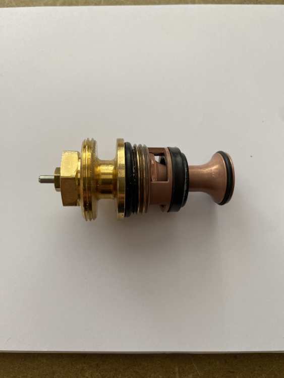
As far as I can tell without stripping it down. When it runs, the flow gauges on the UFH loops all move to their usual positions. I've seen the Ivar youtube video which gives a quick view of the valve block internal mixer arrangement and I've also now removed the valve body itself. As far as I can tell it seems to work exactly as I'd expect and nothing appears broken or missing when I compare it to an online replacement part listing. I assume that it doesn't have any sort of internal wax chamber as the temp control os external to the valve (similar to a TRV) It's the sudden change overnight from working to not-working that's stumped me. Pic of valve attached.
-
Thanks @Nickfromwales Yes, the pin moves freely, Yes there is and it's working fine (the water inlet to the Ivar valve gets nice and hot) I checked the UFH manifold and no air trapped
-
On @Nickfromwales recommendation I fitted an IVAR blending valve which has been absolutely faultless (and silent) for over 5 years. This morning the UFH downstairs was cold despite the boiler running with flow temps of 45deg. Further investigation showed the manifold temp was 20deg and, even when I removed the thermostatic head the temperature didn't change. Is it likely the thermostatic valve has failed, or could it be something else? As an aside, what should the Kv dial be set at? It's been on 0.1 since install so I presume that's fine.
-
@Thorfun good spot this 👍 Just had a look at the specs. As with Mike's other products it's well thought out and designed. Similar max power throughput (8A) as Loxone but higher single channel at 3A (instead of Loxone's 2A) but the biggest difference is the PWM rate. Loxone is 123Hz which is quite low and some people can sometimes detect a hint of flicker, also very noticeable if you've ever taken a video on your phone with the lights on. White wing is 750Hz which is massively different and no chance of any unwanted effects.
-
I have a dealer account with FA. Drop me a PM if you want help with this.
-
Am planning on a couple of shed builds over the next 6-12 months, small one (2m2) for garden tools and a larger one (8m2) as a workshop. Intending to use 45x45 framing, OSB roof and shiplap or T&G cladding. Will a second fix nail gun be better than screws, especially for the cladding?
-
You can sign up to Octoprice ( https://www.octopriceuk.app/missingData) using your Octopus API key and it will tell you whether there is any missed half hour data from your smart meters. It also has other useful stuff on tariffs.
-
Complete with something in the middle to aim at 🤣
-
Loxone Server Backup System
Rob99 replied to tuftythesquirrel's topic in Networks, AV, Security & Automation
Hardware failures of the Miniserver are relatively rare but if they do happen then swapping it out for a replacement is fairly quick and straightforward. It's more complicated if you are swapping a Gen1 for a Gen2. I do keep a couple of spare Gen1 and Gen2 Miniservers just in case a client needs a quick replacement to get their system back up and running. The main failures are more likely with the SD cards, so always keep a back up with a recent copy of the config file. The Miniservers are just the hardware, all the system config software is on the SD card.- 1 reply
-
- 2
-

-
They are WAGO Single Height Fused, Ref 2002-1681
-
Velbus Automation - Thoughts?
Rob99 replied to Duncan62's topic in Networks, AV, Security & Automation
Niche is ok as long as its cheaper, better and less flaky than other options. I don't know anyone who has installed or is using Velbus so can't comment on how good or bad it is but it seemed to me a bit like a KNX bus type system. The programming software did look a bit clunky, although that could be the way the guy was demonstrating it. Lots of people on here have used Loxone (me included), some also use KNX, probably fewer with Control4 or Crestron. Some initial questions I'd be asking are: How popular is the system in the UK and who sells it (if not the manufacturer) What support is available (e.g. community forums, manufacturer, installer) and is it chargeable. Maintenance/software/firmware updates (how, who, how much?) Can you make changes to programming yourself, or is it an "engineer" only system (and therefore chargeable)
